- Table of Contents
-
- 08-Configuration Examples
- 01-Web Login Configuration Examples
- 02-Internet Access Through a Static IP Address Configuration Examples
- 03-Internet access through PPPoE configuration examples
- 04-Signature Library Upgrade Configuration Examples
- 04-Software Upgrade Examples(only for F50X0-D and F5000-AK5X5 firewalls)
- 05-Software Upgrade Examples
- 06-Static routing configuration examples
- 07-OSPF configuration examples
- 08-BGP configuration examples
- 09-RIP configuration examples
- 10-DHCP configuration examples
- 11-DNS configuration examples
- 12-Object Group Configuration Examples
- 13-Public key management configuration examples
- 14-Security Policy Configuration Examples
- 15-Attack defense configuration examples
- 16-Connection Limit Configuration Examples
- 17-IPS Configuration Examples
- 18-URL Filtering Configuration Examples
- 19-Anti-Virus Configuration Examples
- 20-Data Filtering Configuration Examples
- 21-File Filtering Configuration Examples
- 22-APR-Based Security Policy Configuration Examples
- 23-Bandwidth Management Configuration Examples
- 24-NAT configuration examples
- 25-NAT hairpin configuration examples
- 26-IPsec configuration examples
- 27-SSL VPN configuration examples
- 28-Server Load Balancing Configuration Examples
- 29-Outbound Link Load Balancing Configuration Examples
- 30-Inbound Link Load Balancing Configuration Examples
- 31-Transparent DNS Proxy Configuration Examples
- 32-Context Configuration Examples
- 32-Context Configuration Examples(only for F50X0-D and F5000-AK5X5 firewalls)
- 33-IRF configuration examples
- 34-High Availability Group Configuration Examples
- 35-NAT Flow Logging Configuration Examples
- 36-User identification configuration examples
- 37-Server Connection Detection Configuration Examples
- 38-IP Reputation Configuration Examples
- 39-NPTv6 Configuration Examples
- 40-SSL Decryption Configuration Examples
- 41-MAC Address Learning Through a Layer 3 Device Configuration Examples
- 42-WAF Configuration Examples
- 43-NetShare Control Configuration Examples
- 44-4G Configuration Examples
- 45-WLAN Configuration Examples
- Related Documents
-
| Title | Size | Download |
|---|---|---|
| 03-Internet access through PPPoE configuration examples | 318.89 KB |
Internet access through PPPoE configuration examples
Introduction
The following information provides Internet access through PPPoE examples.
This document is not restricted to specific software or hardware versions. Procedures and information in the examples might be slightly different depending on the software or hardware version of the device.
The configuration examples were created and verified in a lab environment, and all the devices were started with the factory default configuration. When you are working on a live network, make sure you understand the potential impact of every command on your network.
The following information is provided based on the assumption that you have basic knowledge of PPPoE.
Network configuration
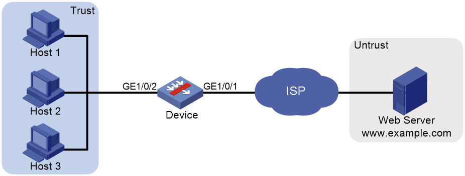
As shown in Figure 1, Device is deployed at the egress of the enterprise network. The enterprise applies for a PPPoE account with the username as pppoeuser1 and password as 123456 from the ISP. Configure PPPoE for users in the enterprise network to access the Web server with the address www.example.com in the Internet.
Software versions used
This configuration example was created and verified on F9345 of the F1060 device.
Restrictions and guidelines
When the device acts as a DHCP server, for the DHCP clients to obtain IP addresses, you must permit the traffic from the security zone where the DHCP-enabled interfaces reside to the local security zone. In this example, you must permit the traffic from security zone Trust to security zone Local.
Procedures
Configuring Device
1. Configure PPPoE.
# On the top navigation bar, click System.
# From the navigation pane, select Configuration Wizard > Internet Access. The page as shown in Figure 2 opens.
Figure 2 Internet Access
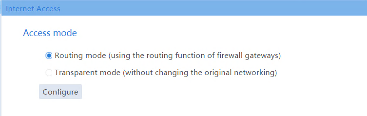
# Select Routing mode, and click Configure. Configure the WAN interface parameters as shown in Figure 3.
Figure 3 WAN interface configuration
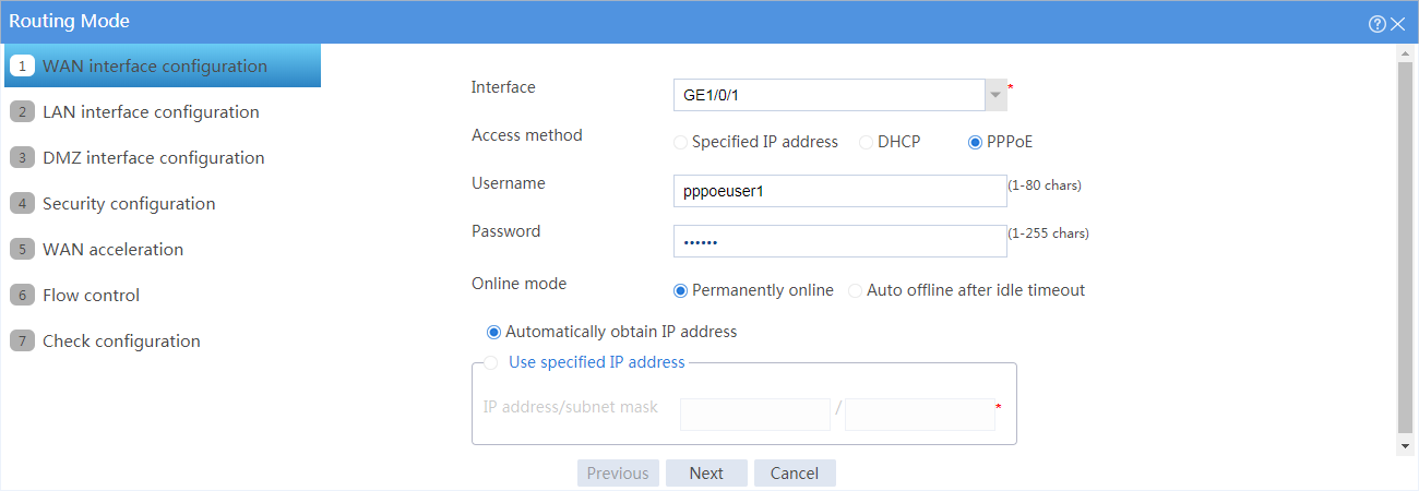
# Click Next. Configure the LAN interface parameters as shown in Figure 4.
Figure 4 LAN interface configuration
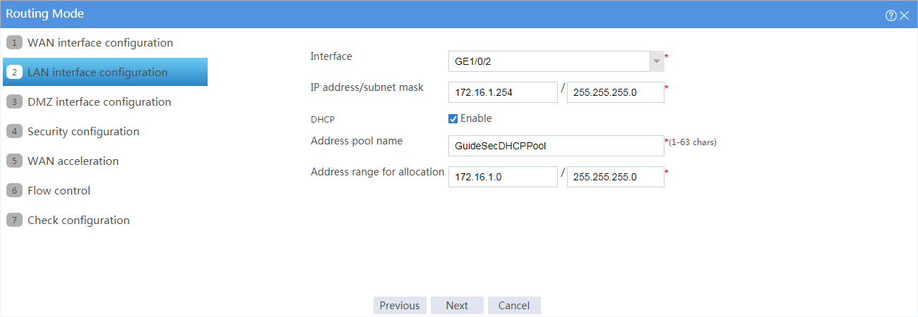
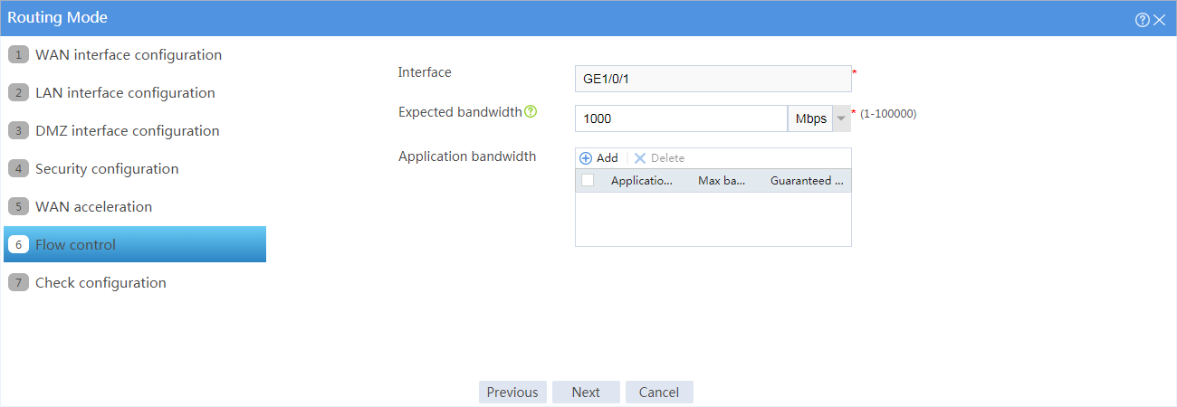
# Click Next. Do not make any DMZ interface, security, or WAN acceleration configuration on the page that opens, and click Next to configure flow control.
# Configure the expected bandwidth for the WAN interface according to the bandwidth allocated by the service provider, as shown in Figure 5.
# Click Next. The Check configuration page as shown in Figure 6 opens.
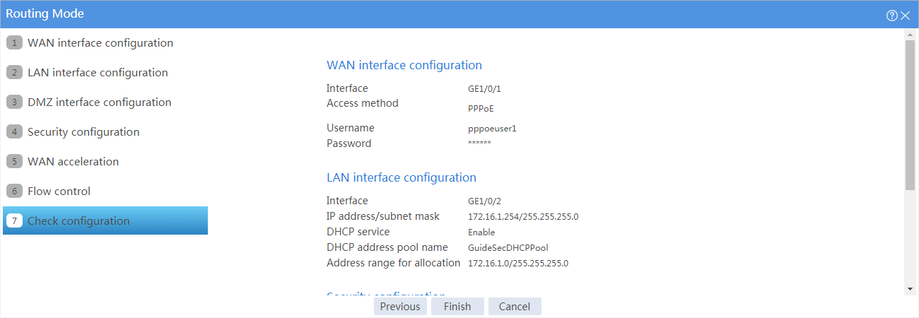
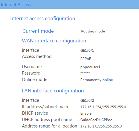
# Verify that the configurations are correct, and click Finish. The PPPoE configuration information is as shown in Figure 7.
Figure 7 PPPoE configuration information
2. Configure a security policy.
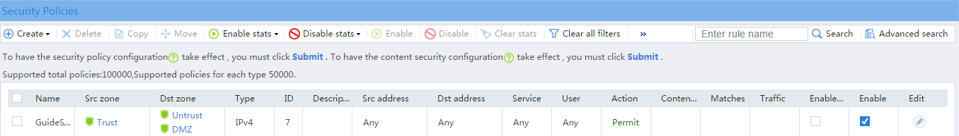
After PPPoE is configured, the system automatically creates a security policy named GuideSecPolicy.
# On the top navigation bar, click Policies.
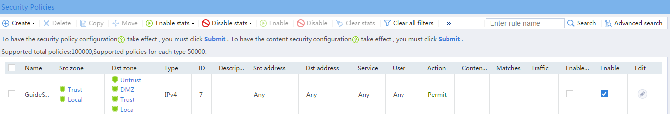
# From the navigation pane, select Security Policies > Security Policies. The Security Policies page as shown in Figure 8 opens.
Figure 8 Security policy configuration page
# Select the security policy GuideSecPolicy, and click the icon in the Edit column. Add the source zone Local, and add the destination zones Trust and Local, as shown in Figure 9.
Figure 9 Adding a security policy
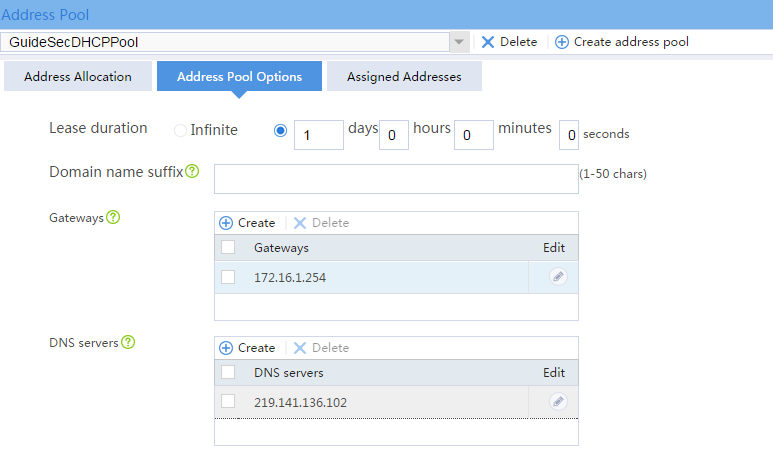
3. Configure DHCP.
# On the top navigation bar, click Network.
# From the navigation pane, select DHCP > DHCP Address Pools.
# Click the Address Pool Options tab. Configure parameters as shown in Figure 10.
Figure 10 Address pool options
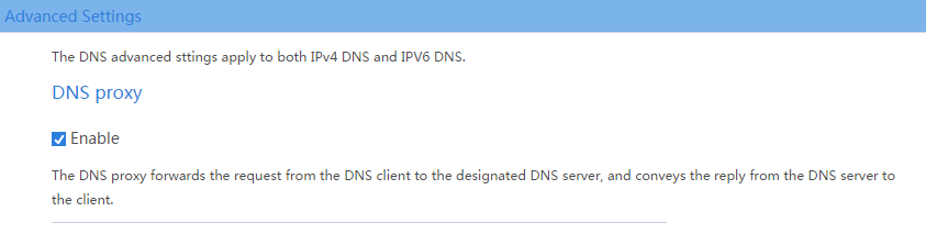
4. Configure DNS proxy.
# On the top navigation bar, click Network.
# From the navigation pane, select DNS > Advanced Settings. On the page as shown in Figure 11, enable DNS proxy.
Configuring the hosts
# Configure the hosts to automatically obtain IP addresses.
Verifying the configuration
1. View the address information that a host obtains.
C:\>ipconfig /all
Ethernet adapter Local Area Connection:
Connection-specific DNS Suffix..........:
Description.......................: Intel(R) 82579LM Gigabit Network Connection
Physical Address....................: E8-39-35-5C-92-B8
DHCP Enabled ................: Yes
Autoconfiguration Enabled...............: Yes
Link-local IPv6 address...........: fe80::b8dd:d091:201a:6db2%13(Preferred)
IPv4 Address...................: 172.16.1.3(Preferred)
Subnet Mask.....................: 255.255.255.0
Lease Obtained................: May 25, 2017 14:01:30
Lease Expires................: May 26, 2017 14:01:30
Default Gateway.....................: 172.16.1.254
DHCP Server..................: 172.16.1.254
DHCPv6 IAID.................: 384317749
DHCPv6 Client DUID...........: 00-01-00-01-1F-B4-A3-F5-B8-A3-86-6F-0F-02
DNS Servers...................: 172.16.1.254
NetBIOS over Tcpip...........: Enabled
2. Verify that a host can ping the server address www.example.com.
C:\>ping www.example.com
Ping www.example.com [192.168.100.201]: 32 data bytes
32 bytes from 192.168.100.201: time<1ms TTL=253
32 bytes from 192.168.100.201: time<1ms TTL=253
32 bytes from 192.168.100.201: time<1ms TTL=253
32 bytes from 192.168.100.201: time<1ms TTL=253
--- Ping statistics for 192.168.100.201 ---
4 packets transmitted, 4 packets received, 0.0% packet loss
round-trip min/avg/max = 0/0/0 ms