- Table of Contents
-
- 08-Configuration Examples
- 01-Web Login Configuration Examples
- 02-Internet Access Through a Static IP Address Configuration Examples
- 03-Internet access through PPPoE configuration examples
- 04-Signature Library Upgrade Configuration Examples
- 04-Software Upgrade Examples(only for F50X0-D and F5000-AK5X5 firewalls)
- 05-Software Upgrade Examples
- 06-Static routing configuration examples
- 07-OSPF configuration examples
- 08-BGP configuration examples
- 09-RIP configuration examples
- 10-DHCP configuration examples
- 11-DNS configuration examples
- 12-Object Group Configuration Examples
- 13-Public key management configuration examples
- 14-Security Policy Configuration Examples
- 15-Attack defense configuration examples
- 16-Connection Limit Configuration Examples
- 17-IPS Configuration Examples
- 18-URL Filtering Configuration Examples
- 19-Anti-Virus Configuration Examples
- 20-Data Filtering Configuration Examples
- 21-File Filtering Configuration Examples
- 22-APR-Based Security Policy Configuration Examples
- 23-Bandwidth Management Configuration Examples
- 24-NAT configuration examples
- 25-NAT hairpin configuration examples
- 26-IPsec configuration examples
- 27-SSL VPN configuration examples
- 28-Server Load Balancing Configuration Examples
- 29-Outbound Link Load Balancing Configuration Examples
- 30-Inbound Link Load Balancing Configuration Examples
- 31-Transparent DNS Proxy Configuration Examples
- 32-Context Configuration Examples
- 32-Context Configuration Examples(only for F50X0-D and F5000-AK5X5 firewalls)
- 33-IRF configuration examples
- 34-High Availability Group Configuration Examples
- 35-NAT Flow Logging Configuration Examples
- 36-User identification configuration examples
- 37-Server Connection Detection Configuration Examples
- 38-IP Reputation Configuration Examples
- 39-NPTv6 Configuration Examples
- 40-SSL Decryption Configuration Examples
- 41-MAC Address Learning Through a Layer 3 Device Configuration Examples
- 42-WAF Configuration Examples
- 43-NetShare Control Configuration Examples
- 44-4G Configuration Examples
- 45-WLAN Configuration Examples
- Related Documents
-
| Title | Size | Download |
|---|---|---|
| 08-BGP configuration examples | 616.08 KB |
Introduction
The following information provides BGP configuration examples.
This document is not restricted to specific software or hardware versions. Procedures and information in the examples might be slightly different depending on the software or hardware version of the device.
The configuration examples were created and verified in a lab environment, and all the devices were started with the factory default configuration. When you are working on a live network, make sure you understand the potential impact of every command on your network.
The following information is provided based on the assumption that you have basic knowledge of BGP.
Network configuration
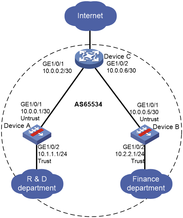
As shown in Figure 1, Device A and Device B are connected to R&D and finance departments, respectively. Device C is a router that acts as the gateway to the Internet.
Configure BGP on the devices to enable the R&D and finance departments to learn routing information from each other. Configure a default route with the next hop being gateway address 200.2.2.254 on Device C, and redistribute the default route to BGP.
Software versions used
This configuration example was created and verified on F9345 of the F1060 device.
Restrictions and guidelines
BGP uses TCP (port number 179) to establish peer relationships. You must configure a security policy to permit the traffic between the local security zone and the security zones that contain the BGP interfaces. For more information, see the configuration procedure.
By default, BGP does not redistribute default IGP routes. To redistribute default IGP routes into the BGP routing table, you must use the default-route imported command together with the import-route command.
Procedure
Configuring Device A
1. Assign IP addresses to interfaces and add the interfaces to security zones.
# On the top navigation bar, click Network.
# From the navigation pane, select Interface Configuration > Interfaces.
# Click the Edit icon for GE 1/0/1.
# In the dialog box that opens, configure the interface:
a. Select the Untrust security zone.
b. On the IPv4 Address tab, enter the IP address and mask of the interface. In this example, enter 10.0.0.1/30.
c. Retain the default configuration for the rest of parameters.
d. Click OK.
# Add GE 1/0/2 to the Trust security zone and set its IP address to 10.1.1.1/24 in the same way you configure GE 1/0/1.
2. Create security policies.
# On the top navigation bar, click Policies.
# From the navigation pane, select Security Policies > Security Policies.
# Select Create > Create a policy.
# Create security policy bgp-a:
¡ Enter policy name bgp-a.
¡ Select source zone Trust.
¡ Select destination zone Untrust.
¡ Select type IPv4.
¡ Select action Permit.
¡ Enter 10.1.1.0/24 as the source address.
¡ Retain the default configuration for the rest of parameters.
# Click OK.
# Create security policy bgp-b:
¡ Enter policy name bgp-b.
¡ Select source zone Local.
¡ Select destination zone Untrust.
¡ Select type IPv4.
¡ Select service object group bgp.
¡ Select action Permit.
¡ Retain the default configuration for the rest of parameters.
# Click OK.
# Create security policy bgp-c:
¡ Enter policy name bgp-c.
¡ Select source zone Untrust.
¡ Select destination zone Local.
¡ Select type IPv4.
¡ Select service object group bgp.
¡ Select action Permit.
¡ Retain the default configuration for the rest of parameters.
# Click OK.
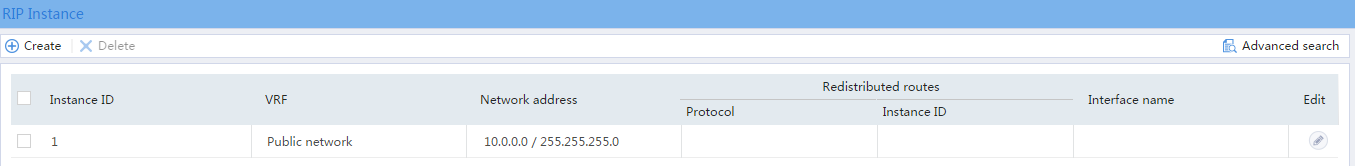
3. Configure an underlying routing protocol. In this example, configure RIP.
# On the top navigation bar, click Network.
# From the navigation pane, select Routing > RIP.
# Click Create.
# In the dialog box that opens, configure a RIP instance.
Figure 2 RIP instance
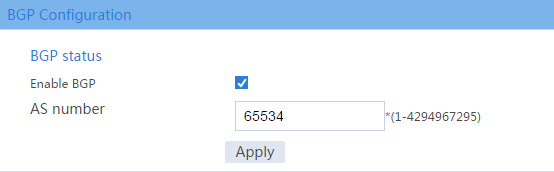
4. Configure BGP.
# On the top navigation bar, click Network.
# From the navigation pane, select Routing > BGP.
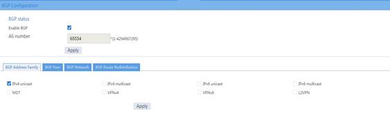
# Select Enable BGP, enter AS number 65534, and then click Apply.
Figure 3 Configuring BGP
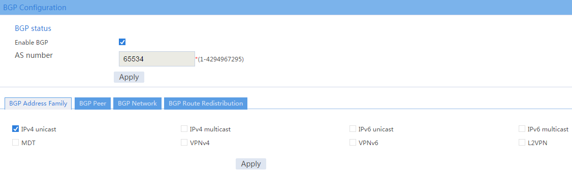
# On the BGP Address Family tab, select an address family, and then click Apply.
Figure 4 Selecting a BGP address family
# On the BGP Peer tab, click Create.
# In the dialog box that opens, specify a BGP peer, and then click OK.
Figure 5 Specifying a BGP peer

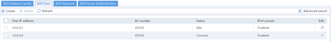
# Repeat the above two steps to specify another BGP peer.
Figure 6 Specifying another BGP peer

Figure 7 BGP peers
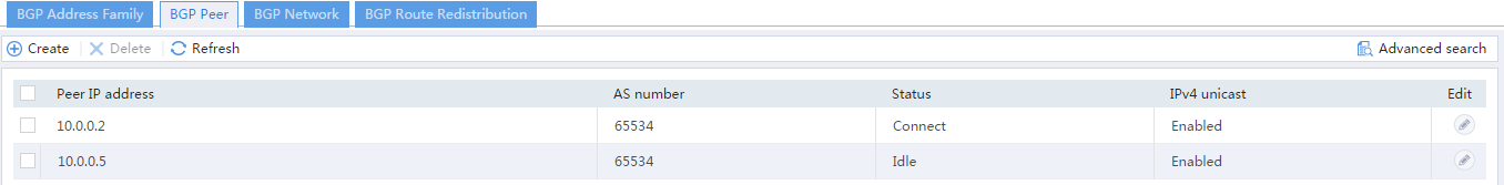
# On the BGP Network tab, click Create.
# In the dialog box that opens, specify the network to be advertised for the specified address family, and then click OK.
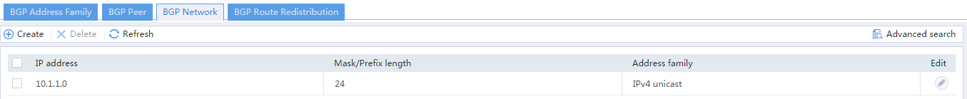
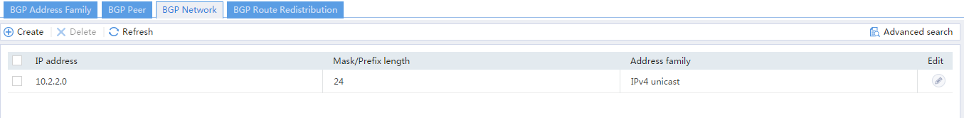
Figure 8 BGP network advertisement
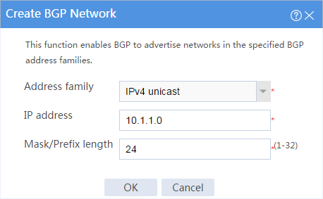
Figure 9 BGP network advertisement
Configuring Device B
1. Assign IP addresses to interfaces and add the interfaces to security zones.
# On the top navigation bar, click Network.
# From the navigation pane, select Interface Configuration > Interfaces.
# Click the Edit icon for GE 1/0/1.
# In the dialog box that opens, configure the interface:
a. Select the Untrust security zone.
b. On the IPv4 Address tab, enter the IP address and mask of the interface. In this example, enter 10.0.0.5/30.
c. Retain the default configuration for the rest of parameters.
d. Click OK.
# Add GE 1/0/2 to the Trust security zone and set its IP address to 10.2.2.1/24 in the same way you configure GE 1/0/1.
2. Create security policies.
# On the top navigation bar, click Policies.
# From the navigation pane, select Security Policies > Security Policies.
# Select Create > Create a policy.
# Create security policy bgp-a:
¡ Enter policy name bgp-a.
¡ Select source zone Trust.
¡ Select destination zone Untrust.
¡ Select type IPv4.
¡ Select action Permit.
¡ Enter 10.2.2.0/24 as the source address.
¡ Retain the default configuration for the rest of parameters.
# Click OK.
# Create security policy bgp-b:
¡ Enter policy name bgp-a.
¡ Select source zone Local.
¡ Select destination zone Untrust.
¡ Select type IPv4.
¡ Select service object group bgp.
¡ Select action Permit.
¡ Retain the default configuration for the rest of parameters.
# Click OK.
# Create security policy bgp-c:
¡ Enter policy name bgp-c.
¡ Select source zone Untrust.
¡ Select destination zone Local.
¡ Select type IPv4.
¡ Select service object group bgp.
¡ Select action Permit.
¡ Retain the default configuration for the rest of parameters.
# Click OK.
3. Configure an underlying routing protocol. In this example, configure RIP.
# On the top navigation bar, click Network.
# From the navigation pane, select Routing > RIP.
# Click Create.
# In the dialog box that opens, configure a RIP instance.
Figure 10 RIP instance

4. Configure BGP.
# On the top navigation bar, click Network.
# From the navigation pane, select Routing > BGP.
# Select Enable BGP, enter AS number 65534, and then click Apply.
Figure 11 Configuring BGP

# On the BGP Address Family tab, select an address family, and then click Apply.
Figure 12 Selecting a BGP address family
# On the BGP Peer tab, click Create.
# In the dialog box that opens, specify a BGP peer, and then click OK.
Figure 13 Specifying a BGP peer

# Repeat the above two steps to specify another BGP peer.
Figure 14 Specifying another BGP peer
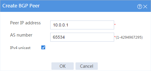
Figure 15 BGP peers
# On the BGP Network tab, click Create.
# In the dialog box that opens, specify the network to be advertised for the specified address family, and then click OK.
Figure 16 BGP network advertisement
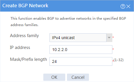
Figure 17 BGP network advertisement
Configuring Device C
1. Assign IP addresses to interfaces. (Details not shown.)
2. Configure an underlying routing protocol. In this example, configure RIP.
<Device C> system-view
[Device C]rip
[Device C-rip-1]network 10.0.0.0 0.0.0.255
3. Configure BGP.
# Enable BGP.
<Device C> system-view
[Device C] bgp 65534
# Specify BGP peers.
[Device C-bgp-default]peer 10.0.0.1 as 65534
[Device C-bgp-default]peer 10.0.0.5 as 65534
# Enable BGP peers.
[Device C-bgp-default]address-family ipv4 unicast
[Device C-bgp-default-ipv4]peer 10.0.0.1 enable
[Device C-bgp-default-ipv4]peer 10.0.0.5 enable
[Device C-bgp-default-ipv4]quit
[Device C-bgp-default]quit
# Configure the default route to the ISP.
[Device C] ip route-static 0.0.0.0 0 200.2.2.254
# Redistribute the default route to the BGP routing table.
[Device C]bgp 65534
[Device C-bgp-default]address-family ipv4 unicast
[Device C-bgp-default-ipv4]import-route static
[Device C-bgp-default-ipv4]default-route imported
Verifying the configuration
1. View information about BGP peers of Device A.
# On the top navigation bar, click Network.
# From the navigation pane, select Routing > BGP.
# On the BGP Peer tab, verify that the BGP peers are in Established state.
Figure 18 BGP routing table of Device A
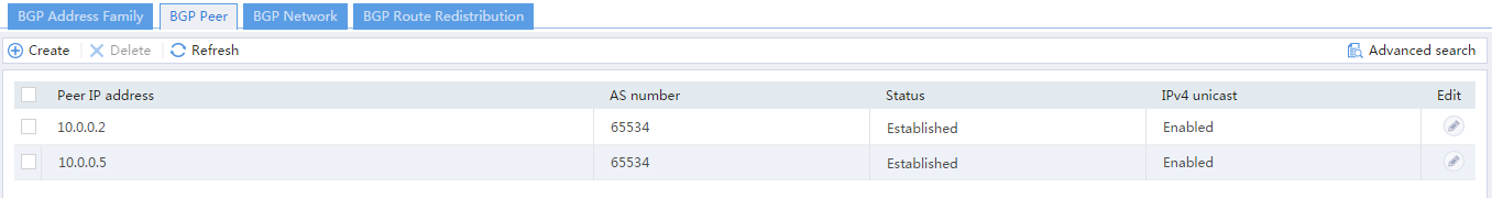
You can see that the BGP peers are in Established state.
2. View information about BGP peers of Device B.
# On the top navigation bar, click Network.
# From the navigation pane, select Routing > BGP.
# On the BGP Peer tab, verify that the BGP peers are in Established state.
Figure 19 BGP routing table of Device B
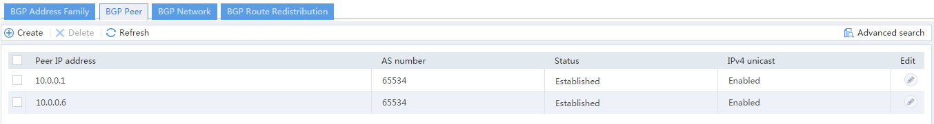
You can see that the BGP peers are in Established state.
3. View information about the BGP routing table of Device A.
# On the top navigation bar, click Network.
# From the navigation pane, select Routing > Routing Table.
# On the IPv4 Routing Table tab, view the BGP routing table information.
Figure 20 BGP routing table of Device A
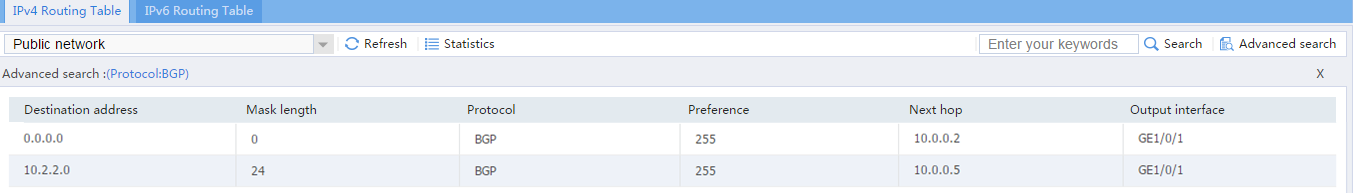
You can see the redistributed BGP route and default route.
4. View information about the BGP routing table of Device B.
# On the top navigation bar, click Network.
# From the navigation pane, select Routing > Routing Table.
# On the IPv4 Routing Table tab, view the BGP routing table information.
Figure 21 BGP routing table of Device B
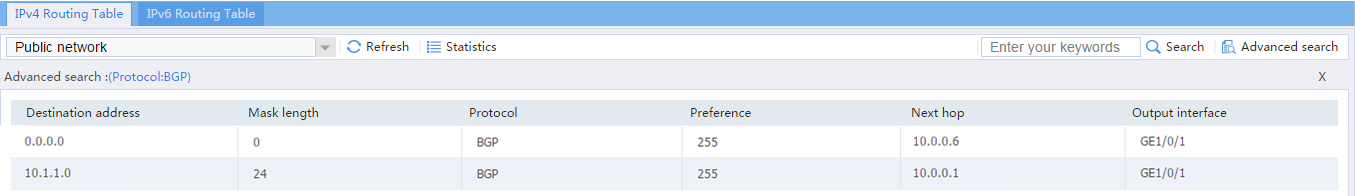
You can see the redistributed BGP route and default route.
5. Verify that Device A can ping the ISP.
<Device A> ping -a 10.1.1.1 200.2.2.254
Ping 200.2.2.254 (200.2.2.254) from 10.1.1.1: 56 data bytes, press CTRL_C to break
56 bytes from 200.2.2.254: icmp_seq=0 ttl=254 time=0.423 ms
56 bytes from 200.2.2.254: icmp_seq=1 ttl=254 time=0.222 ms
56 bytes from 200.2.2.254: icmp_seq=2 ttl=254 time=0.173 ms
56 bytes from 200.2.2.254: icmp_seq=3 ttl=254 time=0.170 ms
56 bytes from 200.2.2.254: icmp_seq=4 ttl=254 time=0.167 ms
--- Ping statistics for 200.2.2.254 ---
5 packet(s) transmitted, 5 packet(s) received, 0.0% packet loss
round-trip min/avg/max/std-dev = 0.167/0.231/0.423/0.098 ms
The output shows that the ISP can be pinged.
6. Verify that Device B can ping the ISP.
<Device B> ping -a 10.0.0.5 200.2.2.254
Ping 200.2.2.254 (200.2.2.254) from 10.0.0.5: 56 data bytes, press CTRL_C to break
56 bytes from 200.2.2.254: icmp_seq=0 ttl=254 time=0.437 ms
56 bytes from 200.2.2.254: icmp_seq=1 ttl=254 time=0.209 ms
56 bytes from 200.2.2.254: icmp_seq=2 ttl=254 time=0.194 ms
56 bytes from 200.2.2.254: icmp_seq=3 ttl=254 time=0.174 ms
56 bytes from 200.2.2.254: icmp_seq=4 ttl=254 time=0.179 ms
--- Ping statistics for 200.2.2.254 ---
5 packet(s) transmitted, 5 packet(s) received, 0.0% packet loss
round-trip min/avg/max/std-dev = 0.174/0.239/0.437/0.100 ms
The output shows that the ISP can be pinged.