- Table of Contents
-
- 08-Configuration Examples
- 01-Web Login Configuration Examples
- 02-Internet Access Through a Static IP Address Configuration Examples
- 03-Internet access through PPPoE configuration examples
- 04-Signature Library Upgrade Configuration Examples
- 04-Software Upgrade Examples(only for F50X0-D and F5000-AK5X5 firewalls)
- 05-Software Upgrade Examples
- 06-Static routing configuration examples
- 07-OSPF configuration examples
- 08-BGP configuration examples
- 09-RIP configuration examples
- 10-DHCP configuration examples
- 11-DNS configuration examples
- 12-Object Group Configuration Examples
- 13-Public key management configuration examples
- 14-Security Policy Configuration Examples
- 15-Attack defense configuration examples
- 16-Connection Limit Configuration Examples
- 17-IPS Configuration Examples
- 18-URL Filtering Configuration Examples
- 19-Anti-Virus Configuration Examples
- 20-Data Filtering Configuration Examples
- 21-File Filtering Configuration Examples
- 22-APR-Based Security Policy Configuration Examples
- 23-Bandwidth Management Configuration Examples
- 24-NAT configuration examples
- 25-NAT hairpin configuration examples
- 26-IPsec configuration examples
- 27-SSL VPN configuration examples
- 28-Server Load Balancing Configuration Examples
- 29-Outbound Link Load Balancing Configuration Examples
- 30-Inbound Link Load Balancing Configuration Examples
- 31-Transparent DNS Proxy Configuration Examples
- 32-Context Configuration Examples
- 32-Context Configuration Examples(only for F50X0-D and F5000-AK5X5 firewalls)
- 33-IRF configuration examples
- 34-High Availability Group Configuration Examples
- 35-NAT Flow Logging Configuration Examples
- 36-User identification configuration examples
- 37-Server Connection Detection Configuration Examples
- 38-IP Reputation Configuration Examples
- 39-NPTv6 Configuration Examples
- 40-SSL Decryption Configuration Examples
- 41-MAC Address Learning Through a Layer 3 Device Configuration Examples
- 42-WAF Configuration Examples
- 43-NetShare Control Configuration Examples
- 44-4G Configuration Examples
- 45-WLAN Configuration Examples
- Related Documents
-
| Title | Size | Download |
|---|---|---|
| 25-NAT hairpin configuration examples | 157.25 KB |
NAT hairpin configuration examples
Introduction
The following information describes NAT hairpin configuration examples.
Prerequisites
This document is not restricted to specific software or hardware versions. Procedures and information in the examples might be slightly different depending on the software or hardware version of the device.
The configuration examples were created and verified in a lab environment, and all the devices were started with the factory default configuration. When you are working on a live network, make sure you understand the potential impact of every command on your network.
The following information is provided based on the assumption that you have basic knowledge of NAT.
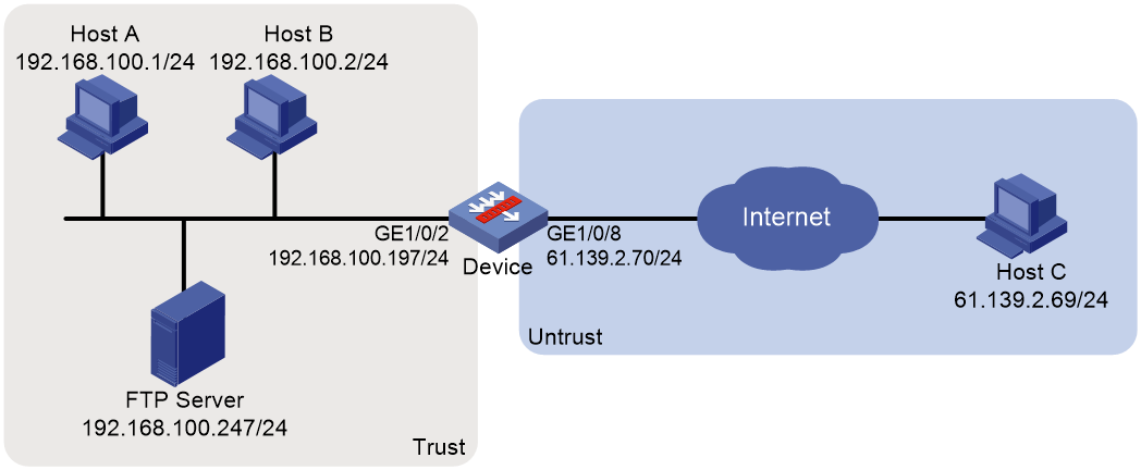
Network configuration
As shown in Figure 1, the internal FTP server at 192.168.100.247/24 provides services for internal and external users. Configure NAT hairpin in C/S mode to allow external and internal users to access the internal FTP server by using public IP address 61.139.2.70/24.
Analysis
This example is a typical use of NAT hairpin in C/S mode. To meet the network requirements, perform the following tasks:
· To allow internal hosts to access the internal FTP server by using a public IP address, enable NAT hairpin on the interface connected to the internal network. Configure outbound NAT on the interface where the NAT server mapping is configured. The destination address is translated by matching the NAT server mapping. The source address is translated by matching the outbound NAT.
· To allow external hosts to access the internal FTP server by using a public IP address, configure NAT Server on the interface connected to the external network.
Software versions used
This configuration example was created and verified on F9345 of the F1060 device.
Procedure
1. Assign IP addresses to interfaces and add the interfaces to security zones.
# On the top navigation bar, click Network.
# From the navigation pane, select Interface Configuration > Interfaces.
# Click the Edit icon for GE 1/0/2.
# In the dialog box that opens, configure the interface:
a. Select the Trust security zone.
b. On the IPv4 Address tab, enter the IP address and mask of the interface. In this example, enter 192.168.100.197/24.
c. Click OK.
# Add GE 1/0/8 to the Untrust security zone and set its IP address to 61.139.2.70/24 in the same way you configure GE 1/0/1.
2. Configure security policy Secpolicy1.
# On the top navigation bar, click Policies.
# From the navigation pane, select Security Policies > Security Policies.
# Click Create and click Create a policy.
# In the dialog box that opens, configure policy parameters as follows:
a. Specify the policy name. In this example, the name is Secpolicy1.
b. Select the Trust security zone as the source zone.
c. Select the Trust security zone as the destination zone.
d. Select IPv4 as the type.
e. Select Permit as the action.
f. Specify the IP address of GE 1/0/8 as the source IPv4 address. In this example, the address is 61.139.2.70/24.
g. Specify the IP address of FTP server as the destination IPv4 address. In this example, the address is 192.168.100.247/24.
h. Click OK. The configuration is shown in Figure 2.
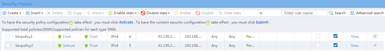
3. Configure security policy Secpolicy2.
# On the top navigation bar, click Policies.
# From the navigation pane, select Security Policies > Security Policies.
# Click Create and click Create a policy.
# In the dialog box that opens, configure policy parameters as follows:
a. Specify the policy name. In this example, the name is Secpolicy2.
b. Select the Untrust security zone as the source zone.
c. Select the Trust security zone as the source zone.
d. Select IPv4 as the type.
e. Select Permit as the action.
f. Specify the IP address of Host C as the source IPv4 address. In this example, the address is 61.139.2.69/24.
g. Specify the IP address of FTP server as the destination IPv4 address. In this example, the address is 192.168.100.247/24.
h. Click OK. The configuration is shown in Figure 2.
Figure 2 Configuring a security policy
4. Configure NAT.
# On the top navigation bar, click Policies.
# From the navigation pane, select NAT > NAT Servers > Policy Configuration.
# Click Create.
# In the dialog box that opens, create a NAT server rule, as shown in Figure 3.
Figure 3 Creating a NAT server rule
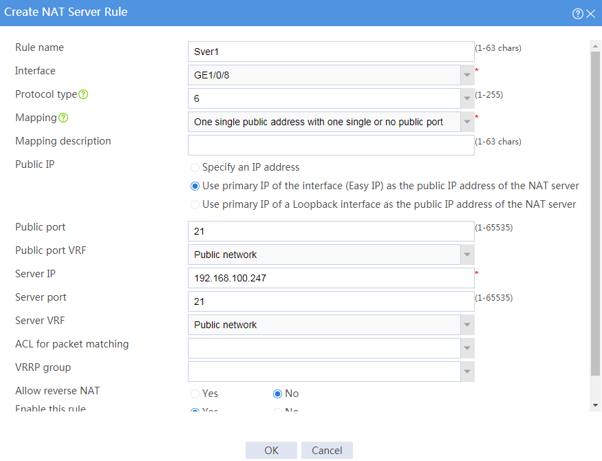
# Click OK.
# On the top navigation bar, click Policies.
# From the navigation pane, select NAT > Dynamic NAT.
# On the Outbound Dynamic NAT (ACL-Based) tab, click Create.
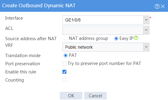
# Create an outbound dynamic NAT rule, as shown in Figure 4.
Figure 4 Creating an outbound dynamic NAT rule
# Click OK.
# On the top navigation bar, click Policies.
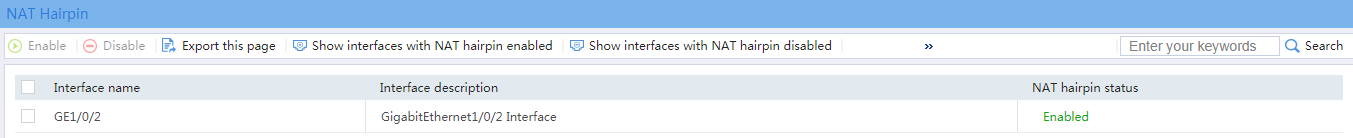
# From the navigation pane, select NAT > NAT Advanced Settings > NAT Hairpin.
# Select GE 1/0/2, and click Enable. GE 1/0/2 is enabled with NAT hairpin, as shown in Figure 5.
Verifying the configuration
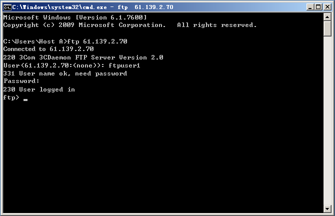
1. Verify that the internal host can access the FTP server by using the public address, as shown in Figure 6.
Figure 6 Connecting to the FTP server from the internal host
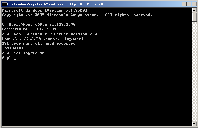
2. Verify that the external host can access the FTP server by using the public address, as shown in Figure 7.
Figure 7 Connecting to the FTP server from the external host
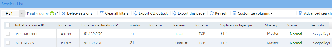
3. Verify that sessions have been created for the internal host and the external host when they access the FTP server.
# On the top navigation bar, click Monitor.
# From the navigation pane, select Sessions.
Figure 8 Session list