- Table of Contents
-
- 08-Configuration Examples
- 01-Web Login Configuration Examples
- 02-Internet Access Through a Static IP Address Configuration Examples
- 03-Internet access through PPPoE configuration examples
- 04-Signature Library Upgrade Configuration Examples
- 04-Software Upgrade Examples(only for F50X0-D and F5000-AK5X5 firewalls)
- 05-Software Upgrade Examples
- 06-Static routing configuration examples
- 07-OSPF configuration examples
- 08-BGP configuration examples
- 09-RIP configuration examples
- 10-DHCP configuration examples
- 11-DNS configuration examples
- 12-Object Group Configuration Examples
- 13-Public key management configuration examples
- 14-Security Policy Configuration Examples
- 15-Attack defense configuration examples
- 16-Connection Limit Configuration Examples
- 17-IPS Configuration Examples
- 18-URL Filtering Configuration Examples
- 19-Anti-Virus Configuration Examples
- 20-Data Filtering Configuration Examples
- 21-File Filtering Configuration Examples
- 22-APR-Based Security Policy Configuration Examples
- 23-Bandwidth Management Configuration Examples
- 24-NAT configuration examples
- 25-NAT hairpin configuration examples
- 26-IPsec configuration examples
- 27-SSL VPN configuration examples
- 28-Server Load Balancing Configuration Examples
- 29-Outbound Link Load Balancing Configuration Examples
- 30-Inbound Link Load Balancing Configuration Examples
- 31-Transparent DNS Proxy Configuration Examples
- 32-Context Configuration Examples
- 32-Context Configuration Examples(only for F50X0-D and F5000-AK5X5 firewalls)
- 33-IRF configuration examples
- 34-High Availability Group Configuration Examples
- 35-NAT Flow Logging Configuration Examples
- 36-User identification configuration examples
- 37-Server Connection Detection Configuration Examples
- 38-IP Reputation Configuration Examples
- 39-NPTv6 Configuration Examples
- 40-SSL Decryption Configuration Examples
- 41-MAC Address Learning Through a Layer 3 Device Configuration Examples
- 42-WAF Configuration Examples
- 43-NetShare Control Configuration Examples
- 44-4G Configuration Examples
- 45-WLAN Configuration Examples
- Related Documents
-
| Title | Size | Download |
|---|---|---|
| 30-Inbound Link Load Balancing Configuration Examples | 384.76 KB |
Inbound link load balancing configuration examples
Introduction
The following information provides inbound link load balancing configuration examples.
This document is not restricted to specific software or hardware versions. Procedures and information in the examples might be slightly different depending on the software or hardware version of the device.
The configuration examples were created and verified in a lab environment, and all the devices were started with the factory default configuration. When you are working on a live network, make sure you understand the potential impact of every command on your network.
The following information is provided based on the assumption that you have basic knowledge of the inbound link load balancing feature.
Example: Configuring inbound link load balancing
Network configuration
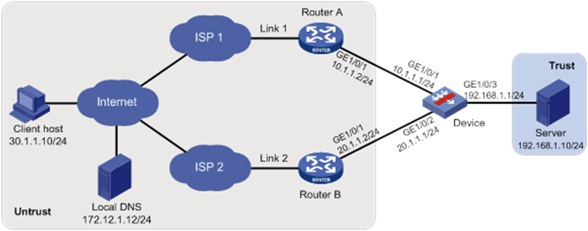
As shown in Figure 1, ISP 1 and ISP 2 provide an enterprise with two links, Link 1 and Link 2. Both links have the same router hop count, bandwidth, and cost.
Configure inbound link load balancing for the device to select an optimal link for traffic from the client host to the server.
Software versions used
This configuration example was created and verified on F9345 of the F1060 device.
Restrictions and guidelines
When you configure inbound link load balancing, follow these restrictions and guidelines:
· To ensure correct operation of inbound link load balancing when server load balancing is also enabled, do not specify the virtual server's IP address as the DNS listener's IP address.
· The virtual server's IPv4 address for inbound link load balancing must be a unicast address with a 32-bit mask length. The IPv4 address cannot be an all-zero address.
· You must contact the ISP to configure a delegating domain on the local DNS server to specify the LB device as the authoritative DNS server.
Procedures
1. Assign IP addresses to interfaces and add the interfaces to security zones.
# On the top navigation bar, click the Network tab.
# From the navigation pane, select Interface Configuration > Interfaces.
# Click the Edit icon for GE 1/0/1.
# In the dialog box that opens, configure the interface:
¡ Select the Untrust security zone.
¡ On the IPv4 Address tab, enter the IP address and mask of the interface. In this example, enter 10.1.1.1/24.
¡ Use the default settings for other parameters.
¡ Click OK.
# Add GE 1/0/2 to the Untrust security zone and set its IP address to 20.1.1.1./24 in the same way you configure GE 1/0/1.
# Add GE 1/0/3 to the Trust security zone and set its IP address to 192.168.1.1/24 in the same way you configure GE 1/0/1.
2. Configure security policies.
# On the top navigation bar, click Policies.
# From the navigation pane, select Security Policies > Security Policies.
# Click Create.
# In the dialog box that opens, configure a security policy named Untrust-to-Trust:
¡ Enter policy name Untrust-to-Trust.
¡ Select source zone Untrust.
¡ Select destination zone Trust.
¡ Select type IPv4.
¡ Select action Permit.
¡ Enter destination IPv4 address 192.168.1.0/24.
¡ Use the default settings for other parameters.
¡ Click OK.
# Configure a security policy named Local-to-Untrust:
¡ Enter policy name Local-to-Untrust.
¡ Select source zone Local.
¡ Select destination zone Untrust.
¡ Select type IPv4.
¡ Select action Permit.
¡ Enter destination IPv4 addresses 10.1.1.0/24 and 20.1.1.0/24.
¡ Use the default settings for other parameters.
¡ Click OK.
3. Configure an ICMP probe template.
# On the top navigation bar, click Objects.
# From the navigation pane, click Health Monitoring.
# Click Create.
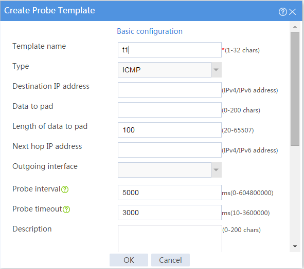
# In the dialog box that opens, configure an ICMP probe template:
a. Enter template name t1.
b. Select type ICMP.
c. Enter 100 for the Length of data to pad field.
d. Enter 5000 for the Probe interval field.
e. Enter 3000 for the Probe timeout field.
f. Click OK.
Figure 2 Creating an ICMP probe template
4. Configure links.
# On the top navigation bar, click Polices.
# From the navigation pane, select Load Balancing > Common Configuration > Links.
# Click Create.
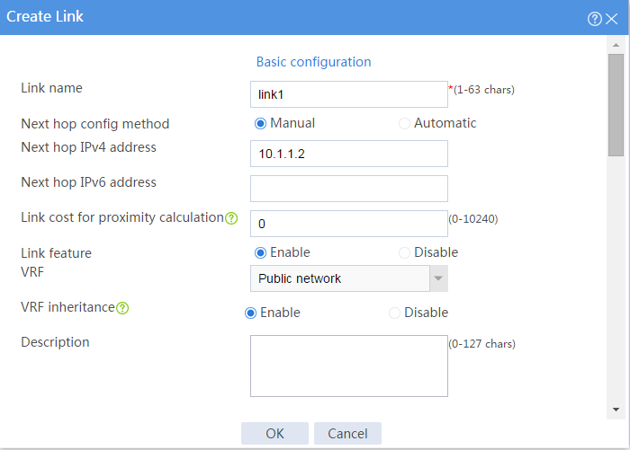
# In the dialog box that opens, configure a link named link1:
Basic configuration:
¡ Enter link name link1.
¡ Select Manual for the Next hop config method field.
¡ Enter next hop IPv4 address 10.1.1.2.
¡ Enable the link feature.
¡ Enable VRF inheritance.
Figure 3 Creating link link1 (basic configuration)
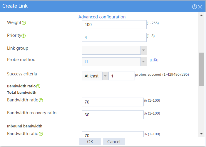
Advanced configuration:
¡ Enter weight 100.
¡ Enter priority 4.
¡ Select probe method t1.
¡ Set the success criteria to At least 1.
¡ Enter total bandwidth ratio 70%.
¡ Enter bandwidth recovery ratio 60%.
¡ Enter inbound bandwidth ratio 70%.
¡ Click OK.
Figure 4 Creating link link1 (advanced configuration)
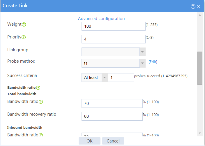
# Configure link link2 in the same way you configure link link1.
Figure 5 Creating link link2 (basic configuration)
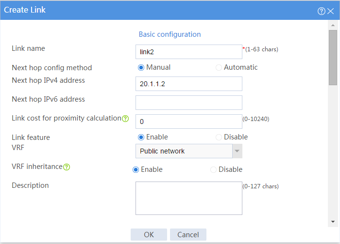
Figure 6 Creating link link2 (advanced configuration)
5. Configure a real server.
# On the top navigation bar, click Polices.
# From the navigation pane, select Load Balancing > Server Load Balancing > Real Servers.
# Click Create.
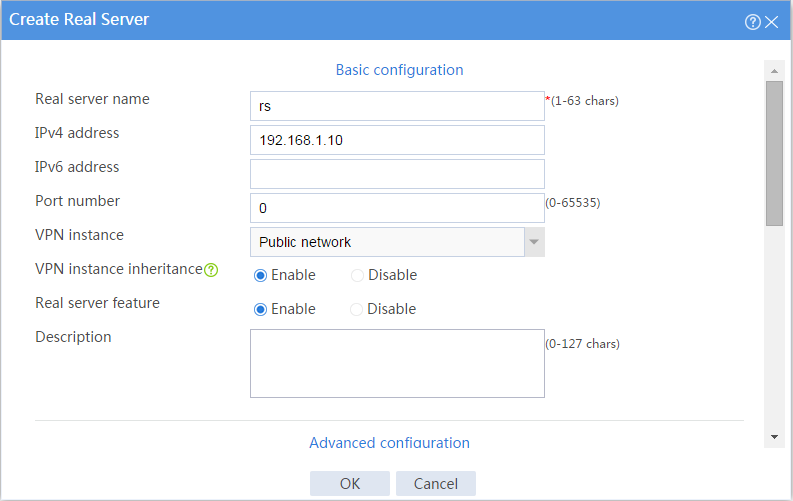
# In the dialog box that opens, configure a real server named rs:
¡ Enter server name rs.
¡ Enter IPv4 address 192.168.1.10.
¡ Enter port number 0.
¡ Enable VRF inheritance.
¡ Enable the real server.
¡ Click OK.
Figure 7 Creating real server rs
6. Configure a server farm.
# On the top navigation bar, click Polices.
# From the navigation pane, select Load Balancing > Server Load Balancing > Server Farms.
# Click Create.
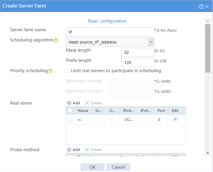
# In the dialog box that opens, configure a server farm named sf:
¡ Enter server farm name sf.
¡ Select scheduling algorithm Hash source_IP_address.
¡ Enter mask length 32 and prefix length 128.
¡ Add real server rs to the server farm.
¡ Select probe method t1.
¡ Click OK.
Figure 8 Creating server farm sf
7. Configure virtual servers.
# On the top navigation bar, click Polices.
# From the navigation pane, select Load Balancing > Server Load Balancing > Virtual Servers.
# Click Create.
# In the dialog box that opens, configure a virtual server named vs1:
¡ Enter server name vs1.
¡ Select type HTTP.
¡ Enter IPv4 address 10.1.1.3.
¡ Enter port number 80.
¡ Select server farm sf.
¡ Disable IP address advertisement.
¡ Enable sticky entry synchronization.
¡ Enable the virtual server.
¡ Click OK.
Figure 9 Creating virtual server vs1
# Configure virtual server vs2 in the same way you configure virtual server vs1.
Figure 10 Creating virtual server vs2
8. Configure a DNS mapping.
# On the top navigation bar, click Polices.
# From the navigation pane, select Load Balancing > Link Load Balancing > Inbound Link LB.
# On the DNS Mapping tab, click Create.
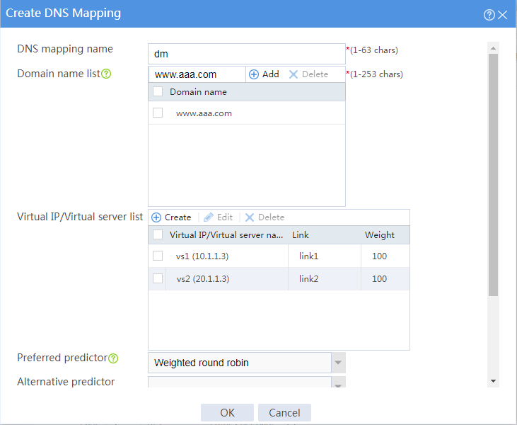
# In the dialog box that opens, configure a DNS mapping named dm:
¡ Enter DNS mapping name dm.
¡ Select virtual IP pool vsp.
¡ Add domain name www.aaa.com to the domain name list.
¡ Set the TTL to 3600 seconds.
¡ Enable DNS mapping.
¡ Click OK.
Figure 11 Creating DNS mapping dm
9. Configure DNS listeners.
# On the top navigation bar, click Polices.
# From the navigation pane, select Load Balancing > Link Load Balancing > Inbound Link LB.
# On the DNS Listener tab, click Create.
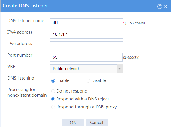
# In the dialog box that opens, configure a DNS listener named dl1:
¡ Enter DNS listener name dl1.
¡ Enter IPv4 address 10.1.1.1.
¡ Enter port number 53.
¡ Enable DNS listening.
¡ Select Respond with a DNS reject for the Processing for nonexistent domain field.
¡ Click OK.
Figure 12 Creating DNS listener d1
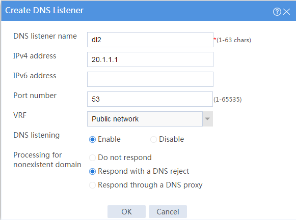
# Configure DNS listener dl2 in the same way you configure DNS listener dl1.
Figure 13 Creating DNS listener dl2
Verifying the configuration
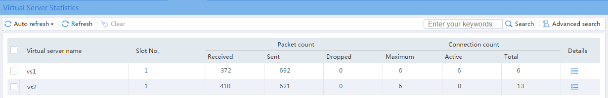
1. Access http://www.aaa.com through the browser on the host, and verify that the device distributes the HTTP requests to the links link1 and link2.
# On the top navigation bar, click the Monitor tab.
# From the navigation pane, select Statistics > Server LB Statistics > Virtual Servers.
The Virtual Server Statistics page is as follows:
Figure 14 Virtual Server statistics

2. Disable virtual server vs1, access http://www.aaa.com through the browser on the host, and verify that the device distributes the HTTP requests to only link link2.
# On the top navigation bar, click the Monitor tab.
# From the navigation pane, select Statistics > Server LB Statistics > Virtual Servers.
The Virtual Server Statistics page is as follows:
Figure 15 Virtual Server statistics

3. Disable virtual server vs2, access http://www.aaa.com through the browser on the host, and verify that the device distributes the HTTP requests to only link link1.
# On the top navigation bar, click the Monitor tab.
# From the navigation pane, select Statistics > Server LB Statistics > Virtual Servers.
The Virtual Server Statistics page is as follows:
Figure 16 Virtual Server statistics