- Table of Contents
-
- 08-Configuration Examples
- 01-Web Login Configuration Examples
- 02-Internet Access Through a Static IP Address Configuration Examples
- 03-Internet access through PPPoE configuration examples
- 04-Signature Library Upgrade Configuration Examples
- 04-Software Upgrade Examples(only for F50X0-D and F5000-AK5X5 firewalls)
- 05-Software Upgrade Examples
- 06-Static routing configuration examples
- 07-OSPF configuration examples
- 08-BGP configuration examples
- 09-RIP configuration examples
- 10-DHCP configuration examples
- 11-DNS configuration examples
- 12-Object Group Configuration Examples
- 13-Public key management configuration examples
- 14-Security Policy Configuration Examples
- 15-Attack defense configuration examples
- 16-Connection Limit Configuration Examples
- 17-IPS Configuration Examples
- 18-URL Filtering Configuration Examples
- 19-Anti-Virus Configuration Examples
- 20-Data Filtering Configuration Examples
- 21-File Filtering Configuration Examples
- 22-APR-Based Security Policy Configuration Examples
- 23-Bandwidth Management Configuration Examples
- 24-NAT configuration examples
- 25-NAT hairpin configuration examples
- 26-IPsec configuration examples
- 27-SSL VPN configuration examples
- 28-Server Load Balancing Configuration Examples
- 29-Outbound Link Load Balancing Configuration Examples
- 30-Inbound Link Load Balancing Configuration Examples
- 31-Transparent DNS Proxy Configuration Examples
- 32-Context Configuration Examples
- 32-Context Configuration Examples(only for F50X0-D and F5000-AK5X5 firewalls)
- 33-IRF configuration examples
- 34-High Availability Group Configuration Examples
- 35-NAT Flow Logging Configuration Examples
- 36-User identification configuration examples
- 37-Server Connection Detection Configuration Examples
- 38-IP Reputation Configuration Examples
- 39-NPTv6 Configuration Examples
- 40-SSL Decryption Configuration Examples
- 41-MAC Address Learning Through a Layer 3 Device Configuration Examples
- 42-WAF Configuration Examples
- 43-NetShare Control Configuration Examples
- 44-4G Configuration Examples
- 45-WLAN Configuration Examples
- Related Documents
-
| Title | Size | Download |
|---|---|---|
| 12-Object Group Configuration Examples | 226.21 KB |
Object group configuration examples
The following information provides examples for configuring IPv4 address, IPv6 address, MAC address, and service object groups and time ranges.
· IPv4 address object group—A group of IPv4 address objects used to match the IPv4 address in a packet.
· IPv6 address object group—A group of IPv6 address objects used to match the IPv6 address in a packet.
· MAC address object group—A group of MAC address objects used to match the MAC address in a packet.
· Service object group—A group of service objects used to match the protocol type and protocol characteristics (such as TCP/UDP source/destination port and ICMP message type and code) in a packet.
· Time range—You can implement a service based on the time of the day by applying a time range to it. A time-based service takes effect only in time periods specified by the time range. If a time range does not exist, the service based on the time range does not take effect.
This document is not restricted to specific software or hardware versions. Procedures and information in the examples might be slightly different depending on the software or hardware version of the device.
The configuration examples were created and verified in a lab environment, and all the devices were started with the factory default configuration. When you are working on a live network, make sure you understand the potential impact of every command on your network.
The following information is provided based on the assumption that you have basic knowledge of the object group feature.
When you configure object groups, follow these restrictions and guidelines:
· The system supports a maximum of five object group hierarchy layers. For example, if groups 1, 2, 3, and 4 use groups 2, 3, 4, and 5, respectively, group 5 cannot use another group and group 1 cannot be used by another group.
· Two object groups cannot use each other at the same time.
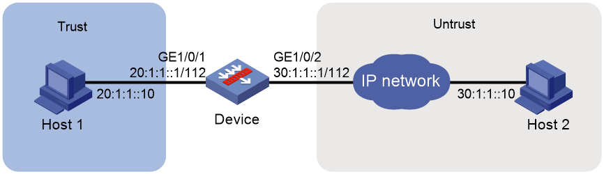
Network configuration
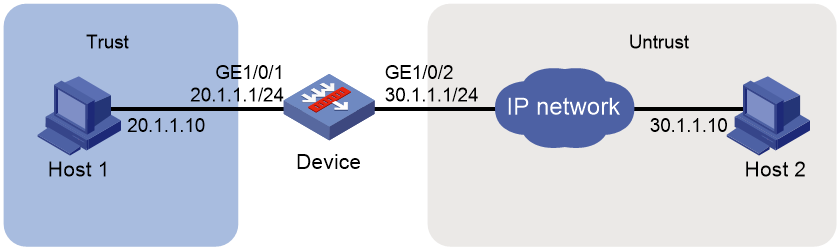
As shown in Figure 1, configure an IPv4 address object group on the device to allow Host 1 to communicate with Host 2.
Software versions used
This configuration example was created and verified on F9345 of the F1060 device.
Procedure
1. Assign IP addresses to interfaces and add the interfaces to security zones.
# On the top navigation bar, click Network.
# From the navigation pane, select Interface Configuration > Interfaces.
# Click the Edit icon for GE 1/0/1.
# In the dialog box that opens, configure the interface:
a. Select the Trust security zone.
b. On the IPv4 Address tab, enter the IP address and mask of the interface. In this example, enter 20.1.1.1/24.
c. Click OK.
# Add GE 1/0/2 to the Untrust security zone and set its IP address to 30.1.1.1./24 in the same way you configure GE 1/0/1.
2. Create an IPv4 address object group.
# On the top navigation bar, click Objects.
# From the navigation pane, select Object Groups > IPv4 Address Object Groups.
# Click Create.
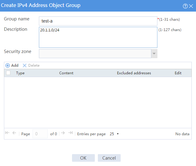
# In the dialog box that opens, configure the IPv4 address object group:
a. Enter a group name. In this example, enter test-a.
b. Enter a description. In this example, enter 20.1.1.0/24.
c. Click Add.
Figure 2 Create an IPv4 address object group
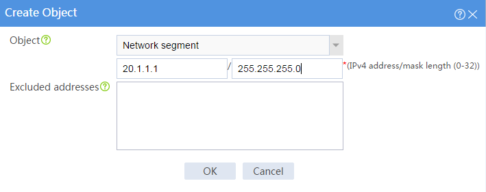
d. In the dialog box that opens, select the Network segment object, and enter the IPv4 address and mask length 20.1.1.0/24.
e. Click OK.
Figure 3 Create an object
f. On the Create IPv4 Address Object Group page, click OK.
3. Create a security policy from zone Trust to zone Untrust.
# On the top navigation bar, click Policies.
# From the navigation pane, select Security Policies > Security Policies.
# Click Create.
# In the dialog box that appears, configure a security policy:
¡ Enter policy name test-a.
¡ Select source zone Trust.
¡ Select destination zone Untrust.
¡ Select type IPv4.
¡ Select action Permit.
¡ Select source IP/MAC address test-a.
# Click OK.
Verifying the configuration
# Verify that you can ping Host 2 from Host 1 successfully.
C:\Users\abc> ping 30.1.1.10
# Follow these steps to view the session information:
1. On the top navigation bar, click Monitor.
2. From the navigation pane, select Sessions.
Example: Configuring an IPv6 address object group
Network configuration
As shown in Figure 4, configure an IPv6 address object group on the device to allow Host 1 to communicate with Host 2.

Software versions used
This configuration example was created and verified on F9345 of the F1060 device.
Procedure
1. Assign IPv6 addresses to interfaces and add the interfaces to security zones.
# On the top navigation bar, click Network.
# From the navigation pane, select Interface Configuration > Interfaces.
# Click the Edit icon for GE 1/0/1.
# In the dialog box that opens, configure the interface:
a. Select the Trust security zone.
b. On the IPv6 Address tab, enter the IP address and mask of the interface. In this example, enter 20:1:1::1/112.
c. Click OK.
# Add GE 1/0/2 to the Untrust security zone and set its IP address to 30:1:1::1/112 in the same way you configure GE 1/0/1.
2. Create an IPv6 address object group.
# On the top navigation bar, click Objects.
# From the navigation pane, select Object Groups > IPv6 Address Object Groups.
# Click Create.
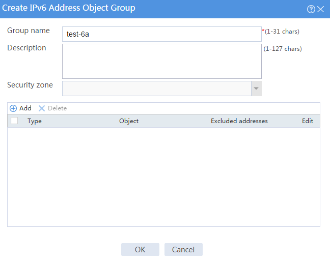
# In the dialog box that opens, configure the IPv6 address object group:
a. Enter a group name. In this example, enter test-6a.
b. Click Add.
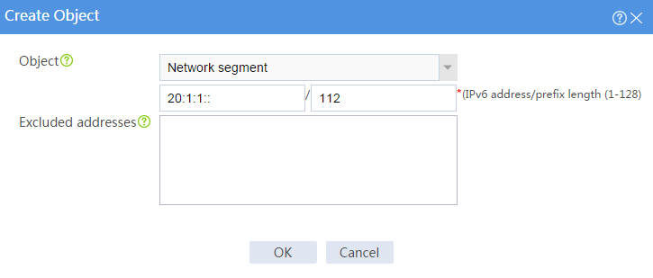
Figure 5 Create an IPv6 address object group
c. In the dialog box that opens, select the Network segment object, and enter the IPv6 address and prefix length 20:1:1::/112.
d. Click OK.
Figure 6 Create an object
e. On the Create IPv6 Address Object Group page, click OK.
3. Create a security policy from zone Trust to zone Untrust.
# On the top navigation bar, click Policies.
# From the navigation pane, select Security Policies > Security Policies.
# Click Create.
# In the dialog box that appears, configure a security policy:
¡ Enter policy name test-6a.
¡ Select source zone Trust.
¡ Select destination zone Untrust.
¡ Select type IPv6.
¡ Select action Permit.
¡ Select source IP/MAC address test-6a.
# Click OK.
Verifying the configuration
# Verify that you can ping Host 2 from Host 1 successfully.
C:\Users\abc> ping 30:1:1::10
# Follow these steps to view the session information:
1. On the top navigation bar, click Monitor.
2. From the navigation pane, select Sessions.
Example: Configuring a MAC address object group
Network configuration
As shown in Figure 7, configure a MAC address object group on the device to allow Host 1 to communicate with Host 2. The MAC address of Host 1 is 3C-52-82-72-03-1F.

Software versions used
This configuration example was created and verified on F9345 of the F1060 device.
Procedure
1. Assign IP addresses to interfaces and add the interfaces to security zones.
# On the top navigation bar, click Network.
# From the navigation pane, select Interface Configuration > Interfaces.
# Click the Edit icon for GE 1/0/1.
# In the dialog box that opens, configure the interface:
a. Select the Trust security zone.
b. On the IPv4 Address tab, enter the IP address and mask of the interface. In this example, enter 20.1.1.1/24.
c. Click OK.
# Add GE 1/0/2 to the Untrust security zone and set its IP address to 30.1.1.1/24 in the same way you configure GE 1/0/1.
2. Create a MAC address object group.
# On the top navigation bar, click Objects.
# From the navigation pane, select Object Groups > MAC Address Object Groups.
# Click Create.
# In the dialog box that opens, configure the MAC address object group:
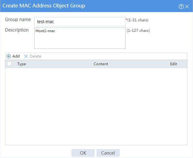
a. Enter a group name. In this example, enter test-mac.
b. Enter a description. In this example, enter Host1-mac.
c. Click Add.
Figure 8 Create a MAC address object group
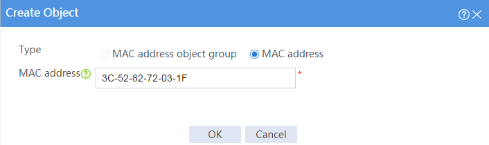
d. In the dialog box that opens, configure a MAC address object.
- Select type MAC address.
- Enter MAC address 3C-52-82-72-03-1F.
e. Click OK.
Figure 9 Create an object
f. On the Create MAC Address Object Group page, click OK.
3. Create a security policy from zone Trust to zone Untrust.
# On the top navigation bar, click Policies.
# From the navigation pane, select Security Policies > Security Policies.
# Click Create.
# In the dialog box that appears, configure a security policy:
¡ Enter policy name test-mac.
¡ Select source zone Trust.
¡ Select destination zone Untrust.
¡ Select type IPv4.
¡ Select action Permit.
¡ Select source IP/MAC address test-mac.
# Click OK.
Verifying the configuration
# Verify that you can ping Host 2 from Host 1 successfully.
C:\Users\abc> ping 30.1.1.10
# Follow these steps to view the session information:
1. On the top navigation bar, click Monitor.
2. From the navigation pane, select Sessions.
Example: Configuring a service object group
Network configuration
As shown in Figure 10, configure a service object group on the device to allow Host 1 to communicate with Host 2 through ICMPv6.
Software versions used
This configuration example was created and verified on F9345 of the F1060 device.
Procedure
1. Assign IPv6 addresses to interfaces and add the interfaces to security zones.
# On the top navigation bar, click Network.
# From the navigation pane, select Interface Configuration > Interfaces.
# Click the Edit icon for GE 1/0/1.
# In the dialog box that opens, configure the interface:
a. Select the Trust security zone.
b. On the IPv6 Address tab, enter the IP address and mask of the interface. In this example, enter 20:1:1::1/112.
c. Click OK.
# Add GE 1/0/2 to the Untrust security zone and set its IP address to 30:1:1::1/112 in the same way you configure GE 1/0/1.
2. Create a service object group.
# On the top navigation bar, click Objects.
# From the navigation pane, select Object Groups > Service Object Groups.
# Click Create.
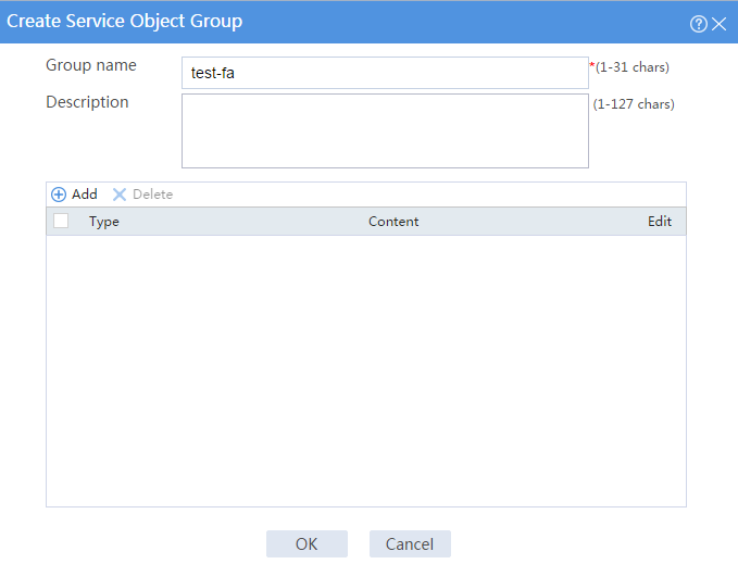
# In the dialog box that opens, configure the service object group:
a. Enter a group name. In this example, enter test-fa.
b. Click Add.
Figure 11 Create a service object group

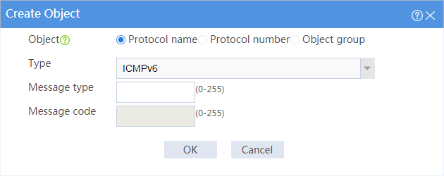
c. In the dialog box that opens, configure a service object.
- Select object Protocol name.
- Select type ICMPv6.
d. Click OK.
Figure 12 Create an object
e. On the Create Service Object Group page, click OK.
3. Create a security policy from zone Trust to zone Untrust.
# On the top navigation bar, click Policies.
# From the navigation pane, select Security Policies > Security Policies.
# Click Create.
# In the dialog box that appears, configure a security policy:
¡ Enter policy name test-fa.
¡ Select source zone Trust.
¡ Select destination zone Untrust.
¡ Select type IPv6.
¡ Select action Permit.
¡ Specify the source IPv6 address as 20.1.1.0/24.
¡ Specify the destination IPv6 address as 220.0.0.0/24.
¡ Select service test-fa.
# Click OK.
Verifying the configuration
# Verify that you can ping Host 2 from Host 1 successfully.
C:\Users\abc> ping 30:1:1::10
# Follow these steps to view the session information:
1. On the top navigation bar, click Monitor.
2. From the navigation pane, select Sessions.
Example: Configuring a time range
Network configuration
As shown in Figure 13, configure a service object group on the device to allow Host 1 to communicate with Host 2 through ICMPv6 in a specific time period.

Software versions used
This configuration example was created and verified on F9345 of the F1060 device.
Procedure
1. Assign IPv6 addresses to interfaces and add the interfaces to security zones.
# On the top navigation bar, click Network.
# From the navigation pane, select Interface Configuration > Interfaces.
# Click the Edit icon for GE 1/0/1.
# In the dialog box that opens, configure the interface:
a. Select the Trust security zone.
b. On the IPv6 Address tab, enter the IP address and mask of the interface. In this example, enter 20:1:1::1/112.
c. Click OK.
# Add GE 1/0/2 to the Untrust security zone and set its IP address to 30:1:1::1/112 in the same way you configure GE 1/0/1.
2. Create a service object group.
# On the top navigation bar, click Objects.
# From the navigation pane, select Object Groups > Service Object Groups.
# Click Create.
# In the dialog box that opens, configure the service object group:
a. Enter a group name. In this example, enter test-fa.
b. Click Add.
Figure 14 Create a service object group
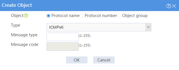
c. In the dialog box that opens, configure a service object.
- Select object Protocol name.
- Select type ICMPv6.
d. Click OK.
Figure 15 Create an object
e. On the Create Service Object Group page, click OK.
3. Create a time range.
# On the top navigation bar, click Object.
# From the navigation pane, select Object Groups > Time Ranges.
# Click Create.
# In the dialog box that appears, enter name test-time and then click Create for Periodic time range.
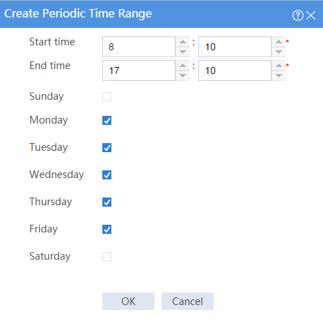
# In the dialog box that appears, configure the time range:
¡ Set the start time to 08:10.
¡ Set the end time to 17:10.
¡ Select Monday, Tuesday, Wednesday, Thursday, and Friday.
# Click OK.
Figure 16 Configure a time range
# In the Create Time Range page, click OK.
4. Create a security policy from zone Trust to zone Untrust.
# On the top navigation bar, click Policies.
# From the navigation pane, select Security Policies > Security Policies.
# Click Create.
# In the dialog box that appears, configure a security policy:
¡ Enter policy name test-time.
¡ Select source zone Trust.
¡ Select destination zone Untrust.
¡ Select type IPv6.
¡ Select action Permit.
¡ Select service test-fa.
¡ Select time range test-time.
# Click OK.
Verifying the configuration
# Verify that you can ping Host 2 from Host 1 successfully in the time period specified by the time range.
C:\Users\abc> ping 30:1:1::10
# Verify that you cannot ping Host 2 from Host 1 and the corresponding session does not exist at any time beyond the time period specified by the time range.