- Table of Contents
-
- 08-System Volume
- 00-System Volume Organization
- 01-Login Configuration
- 02-Basic System Configuration
- 03-Device Management Configuration
- 04-File System Management Configuration
- 05-SNMP Configuration
- 06-RMON Configuration
- 07-MAC Address Table Management Configuration
- 08-System Maintaining and Debugging Configuration
- 09-Information Center Configuration
- 10-PoE Configuration
- 11-Track Configuration
- 12-NQA Configuration
- 13-NTP Configuration
- 14-VRRP Configuration
- 15-HA Configuration
- 16-Hotfix Configuration
- 17-GR Overview
- Related Documents
-
| Title | Size | Download |
|---|---|---|
| 11-Track Configuration | 107.81 KB |
Table of Contents
Collaboration Between the Track Module and the Detection Modules
Collaboration Between the Track Module and the Application Modules
Configuring Collaboration Between the Track Module and the Detection Modules
Configuring Track-NQA Collaboration
Configuring Collaboration Between the Track Module and the Application Modules
Configuring Track-VRRP Collaboration
Configuring Track-Static Routing Collaboration
Displaying and Maintaining Track Object(s)
VRRP-Track-NQA Collaboration Configuration Example
Static Routing-Track-NQA Collaboration Configuration Example
When configuring Track, go to these sections for information you are interested in:
l Track Configuration Task List
l Configuring Collaboration Between the Track Module and the Detection Modules
l Configuring Collaboration Between the Track Module and the Application Modules
l Displaying and Maintaining Track Object(s)
l Track Configuration Examples
Track Overview
Figure 1-1 Collaboration through the Track module
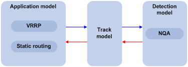
The Track module is used to implement collaboration between different modules.
The collaboration here involves three parts: the application modules, the Track module, and the detection modules. These modules collaborate with one another through collaboration objects. That is, the detection modules trigger the application modules to perform certain operations through the Track module. More specifically, the detection modules probe the link status, network performance and so on, and inform the application modules of the detection result through the Track module. After the application modules are aware of the changes of network status, they deal with the changes accordingly to avoid communication interruption and network performance degradation.
The Track module works between the application modules and the detection modules and is mainly used to obscure the difference of various detection modules to provide a unified interface for application modules.
Collaboration Between the Track Module and the Detection Modules
You can establish the collaboration between the Track module and the detection modules through configuration. A detection module probes the link status and informs the Track module of the probe result. The Track module then changes the status of the Track object accordingly:
l If the probe succeeds, the status of the corresponding Track object is Positive;
l If the probe fails, the status of the corresponding Track object is Negative.
At present, the detection modules that can collaborate with the Track module is the Network Quality Analyzer (NQA) module. Refer to NQA Configuration in the System Volume for details of NQA.
Collaboration Between the Track Module and the Application Modules
You can establish the collaboration between the Track module and the application modules through configuration. If the status of the Track object changes, the Track module tells the application modules to deal with the change accordingly.
At present, the application modules that can collaborate with the Track module include:
l VRRP
l Static routing
Track Configuration Task List
To implement the collaboration function, you need to establish collaboration between the Track module and the detection modules, and between the Track module and the application modules.
Complete these tasks to configure Track module:
|
Task |
Remarks |
|
|
Configuring Collaboration Between the Track Module and the Detection Modules |
— |
|
|
Configuring Collaboration Between the Track Module and the Application Modules |
Use at least one of the two approaches |
|
Configuring Collaboration Between the Track Module and the Detection Modules
Configuring Track-NQA Collaboration
Through the following configuration, you can establish the collaboration between the Track module and the NQA, which probes the link status and informs the Track module of the probe result.
Follow these steps to configure Track-NQA collaboration:
|
To do… |
Use the command… |
Remarks |
|
Enter system view |
system-view |
— |
|
Create a Track object and associate it with the specified Reaction entry of the NQA test group |
track track-entry-number nqa entry admin-name operation-tag reaction item-num |
Required No Track object is created by default. |
![]()
When you configure a Track object, the specified NQA test group and Reaction entry can be nonexistent. In this case, the status of the configured Track object is Invalid.
Configuring Collaboration Between the Track Module and the Application Modules
Configuring Track-VRRP Collaboration
Through the Track-VRRP collaboration, you can:
l Monitor the upper link. If there is a fault on the upper link of the master of a VRRP group, hosts in the LAN cannot access the external network through the master. In this case, the status of the monitored Track object changes to Negative, and the priority of the master thus decreases by a specified value, allowing a higher priority router in the VRRP group to become the master to maintain proper communication between the hosts in the LAN and the external network.
l Monitor the master on a backup. If there is a fault on the master, the backup working in the switchover mode will switch to the master immediately to maintain normal communication.
Configuration prerequisites
Before configuring VRRP to monitor a Track object, you need to create a VRRP group on an interface and configure the virtual IP address of the VRRP group.
Configuration procedure
Follow these steps to configure Track-VRRP collaboration:
|
To do… |
Use the command… |
Remarks |
|
Enter system view |
system-view |
— |
|
Enter interface view |
interface interface-type interface-number |
— |
|
Create a VRRP group and configure its virtual IP address |
vrrp vrid virtual-router-id virtual-ip virtual-address |
Required No VRRP group is created by default. |
|
Specify a Track object to be monitored by VRRP |
vrrp vrid virtual-router-id track track-entry-number [ reduced priority-reduced | switchover ] |
Required No Track object is specified for VRRP by default. |
![]()
l Do not perform Track object monitoring on the IP address owner.
l When the status of the monitored Track object turns from Negative to Positive, the corresponding router restores its priority automatically.
l The monitored Track object can be nonexistent, so that you can first specify the Track object to be monitored using the vrrp vrid track command, and then create the Track object using the track command.
l Refer to VRRP Configuration in the System Volume for details of VRRP.
Configuring Track-Static Routing Collaboration
You can check the validity of a static route in real time by establishing collaboration between Track and static routing.
If you specify the next hop but not the egress interface when configuring a static route, you can associate the static route with a Track object and thus check the validity of the static route according to the status of the Track object.
l If the status of the Track object is Positive, then the next hop of the static route is reachable, and the configured static route is valid.
l If the status of the Track object is Negative, then the next hop of the static route is unreachable, and the configured static route is invalid.
Follow these steps to configure the Track-Static Routing collaboration:
|
To do… |
Use the command… |
Remarks |
|
Enter system view |
system-view |
— |
|
Configure the Track-Static Routing collaboration, so as to check the reachability of the next hop of the static route |
ip route-static dest-address { mask | mask-length } { next-hop-address | vpn-instance d-vpn-instance-name next-hop-address } track track-entry-number [ preference preference-value ] [ tag tag-value ] [ description description-text ] |
Use either command. Not configured by default. |
|
ip route-static vpn-instance s-vpn-instance-name&<1-6> dest-address { mask | mask-length } { next-hop-address track track-entry-number [ public ] | vpn-instance d-vpn-instance-name next-hop-address track track-entry-number } [ preference preference-value ] [ tag tag-value ] [ description description-text ] |
![]()
l For the configuration of Track-Static Routing collaboration, the specified static route can be an existent or nonexistent one. For an existent static route, the static route and the specified Track object are associated directly; for a nonexistent static route, the system creates the static route and then associates it with the specified Track object.
l The Track object to be associated with the static route can be a nonexistent one. After you use the track command to create the Track object, the association takes effect.
l If the Track module detects the next hop reachability of the static route in a private network through NQA, the VPN instance name of the next hop of the static route must be consistent with that configured for the NQA test group. Otherwise, the reachability detection cannot function properly.
l If a static route needs route recursion, the associated Track object must monitor the next hop of the recursive route instead of that of the static route; otherwise, a valid route may be considered invalid.
l For details of static route configuration, refer to Static Routing Configuration in the IP Routing Volume.
Displaying and Maintaining Track Object(s)
|
To do… |
Use the command… |
Remarks |
|
Display information about the specified Track object or all Track objects |
display track { track-entry-number | all } |
Available in any view |
Track Configuration Examples
VRRP-Track-NQA Collaboration Configuration Example
Network requirements
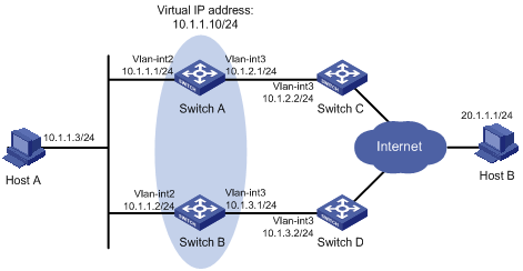
l Host A needs to access Host B on the Internet. The default gateway of Host A is 10.1.1.10/24.
l Switch A and Switch B belong to VRRP group 1, whose virtual IP address is 10.1.1.10.
l When Switch A works normally, packets from Host A to Host B are forwarded through Switch A. When VRRP finds that there is a fault on the upper link of Switch A through NQA, packets from Host A to Host B are forwarded through Switch B.
Network diagram
Figure 1-2 Network diagram for VRRP-Track-NQA collaboration configuration (on switches)
Configuration procedure
1) Configure the IP address of each interface as shown in Figure 1-2.
2) Configure an NQA test group on Switch A.
<SwitchA> system-view
# Create an NQA test group with the administrator name admin and the operation tag test.
[SwitchA] nqa entry admin test
# Configure the test type as ICMP-echo.
[SwitchA-nqa-admin-test] type icmp-echo
# Configure the destination address as 10.1.2.2.
[SwitchA-nqa-admin-test-icmp-echo] destination ip 10.1.2.2
# Set the test frequency to 100 ms.
[SwitchA-nqa-admin-test-icmp-echo] frequency 100
# Configure Reaction entry 1, specifying that five consecutive probe failures trigger the Track-NQA collaboration.
[SwitchA-nqa-admin-test-icmp-echo] reaction 1 checked-element probe-fail threshold-type consecutive 5 action-type trigger-only
[SwitchA-nqa-admin-test-icmp-echo] quit
# Start NQA probes.
[SwitchA] nqa schedule admin test start-time now lifetime forever
3) Configure a Track object on Switch A.
# Configure Track object 1, and associate it with Reaction entry 1 of the NQA test group (with the administrator admin, and the operation tag test).
[SwitchA] track 1 nqa entry admin test reaction 1
4) Configure VRRP on Switch A.
# Create VRRP group 1, and configure the virtual IP address 10.1.1.10 for the group.
[SwitchA] interface vlan-interface 2
[SwitchA-Vlan-interface2] vrrp vrid 1 virtual-ip 10.1.1.10
# Set the priority of Switch A in VRRP group 1 to 110.
[SwitchA-Vlan-interface2] vrrp vrid 1 priority 110
# Set the authentication mode of VRRP group 1 to simple, and the authentication key to hello.
[SwitchA-Vlan-interface2] vrrp vrid 1 authentication-mode simple hello
# Configure the master to send VRRP packets at an interval of five seconds.
[SwitchA-Vlan-interface2] vrrp vrid 1 timer advertise 5
# Configure Switch A to work in preemptive mode, and set the preemption delay to five seconds.
[SwitchA-Vlan-interface2] vrrp vrid 1 preempt-mode timer delay 5
# Configure to monitor Track object 1 and specify the priority decrement to 30.
[SwitchA-Vlan-interface2] vrrp vrid 1 track 1 reduced 30
5) Configure VRRP on Switch B.
<SwitchB> system-view
[SwitchB] interface vlan-interface 2
# Create VRRP group 1, and configure the virtual IP address 10.1.1.10 for the group.
[SwitchB-Vlan-interface2] vrrp vrid 1 virtual-ip 10.1.1.10
# Set the authentication mode of VRRP group 1 to simple, and the authentication key to hello.
[SwitchB-Vlan-interface2] vrrp vrid 1 authentication-mode simple hello
# Configure the master to send VRRP packets at an interval of five seconds.
[SwitchB-Vlan-interface2] vrrp vrid 1 timer advertise 5
# Configure Switch B to work in preemptive mode, and set the preemption delay to five seconds.
[SwitchB-Vlan-interface2] vrrp vrid 1 preempt-mode timer delay 5
6) Verify the configuration
After configuration, ping Host B on Host A, and you can see that Host B is reachable. Use the display vrrp command to view the configuration result.
# Display detailed information about VRRP group 1 on Switch A.
[SwitchA-Vlan-interface2] display vrrp verbose
IPv4 Standby Information:
Run Method : VIRTUAL-MAC
Virtual IP Ping : Enable
Total number of virtual routers: 1
Interface : Vlan-interface2
VRID : 1 Adver. Timer : 5
Admin Status : UP State : Master
Config Pri : 110 Run Pri : 110
Preempt Mode : YES Delay Time : 5
Auth Type : SIMPLE TEXT Key : hello
Track Object : 1 Pri Reduced : 0
Virtual IP : 10.1.1.10
Virtual MAC : 0000-5e00-0101
Master IP : 10.1.1.1
# Display detailed information about VRRP group 1 on Switch B.
[SwitchB-Vlan-interface2] display vrrp verbose
IPv4 Standby Information:
Run Method : VIRTUAL-MAC
Virtual IP Ping : Enable
Total number of virtual routers: 1
Interface : Vlan-interface2
VRID : 1 Adver. Timer : 5
Admin Status : UP State : Backup
Config Pri : 100 Run Pri : 100
Preempt Mode : YES Delay Time : 5
Auth Type : SIMPLE TEXT Key : hello
Virtual IP : 10.1.1.10
Master IP : 10.1.1.1
The above output information indicates that in VRRP group 1, Switch A is the master and Switch B is a backup. Packets from Host A to Host B are forwarded through Switch A.
When there is a fault on the link between Switch A and Switch C, you can still successfully ping Host B on Host A. Use the display vrrp command to view information about VRRP group 1.
# Display detailed information about VRRP group 1 on Switch A when there is a fault on the link between Switch A and Switch C.
[SwitchA-Vlan-interface2] display vrrp verbose
IPv4 Standby Information:
Run Method : VIRTUAL-MAC
Virtual IP Ping : Enable
Total number of virtual routers: 1
Interface : Vlan-interface2
VRID : 1 Adver. Timer : 5
Admin Status : UP State : Backup
Config Pri : 110 Run Pri : 80
Preempt Mode : YES Delay Time : 5
Auth Type : SIMPLE TEXT Key : hello
Track Object : 1 Pri Reduced : 30
Virtual IP : 10.1.1.10
Master IP : 10.1.1.2
# Display detailed information about VRRP group 1 on Switch B when there is a fault on the link between Switch A and Switch C.
[SwitchB-Vlan-interface2] display vrrp verbose
IPv4 Standby Information:
Run Method : VIRTUAL-MAC
Virtual IP Ping : Enable
Total number of virtual routers: 1
Interface : Vlan-interface2
VRID : 1 Adver. Timer : 5
Admin Status : UP State : Master
Config Pri : 100 Run Pri : 100
Preempt Mode : YES Delay Time : 5
Auth Type : SIMPLE TEXT Key : hello
Virtual IP : 10.1.1.10
Virtual MAC : 0000-5e00-0101
Master IP : 10.1.1.2
The output information indicates that when there is a fault on the link between Switch A and Switch C, the priority of Switch A decreases to 80. Switch A becomes the backup, and Switch B becomes the master. Packets from Host A to Host B are forwarded through Switch B.
Static Routing-Track-NQA Collaboration Configuration Example
Network requirements
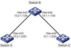
l The next hop of the static route from Switch A to Switch C is Switch B.
l Configure Static Routing-Track-NQA collaboration on Switch A to implement real-time monitoring of the validity of the static route to Switch C.
Network diagram
Figure 1-3 Network diagram for Static Routing-Track-NQA collaboration configuration (on switches)
Configuration procedure
1) Configure the IP address of each interface as shown in Figure 1-3.
2) Configure a static route on Switch A and associate it with the Track object.
# Configure the address of the next hop of the static route to Switch C as 10.2.1.1, and configure the static route to associate with Track object 1.
<SwitchA> system-view
[SwitchA] ip route-static 10.1.1.2 24 10.2.1.1 track 1
3) Configure an NQA test group on Switch A.
# Create an NQA test group with the administrator admin and the operation tag test.
[SwitchA] nqa entry admin test
# Configure the test type as ICMP-echo.
[SwitchA-nqa-admin-test] type icmp-echo
# Configure the destination address as 10.2.1.1
[SwitchA-nqa-admin-test-icmp-echo] destination ip 10.2.1.1
# Configure the test frequency as 100 ms.
[SwitchA-nqa-admin-test-icmp-echo] frequency 100
# Configure Reaction entry 1, specifying that five consecutive probe failures trigger the Static Routing-Track-NQA collaboration.
[SwitchA-nqa-admin-test-icmp-echo] reaction 1 checked-element probe-fail threshold-type consecutive 5 action-type trigger-only
[SwitchA-nqa-admin-test-icmp-echo] quit
# Start NQA probes.
[SwitchA] nqa schedule admin test start-time now lifetime forever
4) Configure a Track object on Switch A.
# Configure Track object 1, and associate it with Reaction entry 1 of the NQA test group (with the administrator admin, and the operation tag test).
[SwitchA] track 1 nqa entry admin test reaction 1
5) Verify the configuration
# Display information of the Track object on Switch A.
[SwitchA] display track all
Track ID: 1
Status: Positive
Reference object:
NQA entry: admin test
Reaction: 1
# Display the routing table of Switch A.
[SwitchA] display ip routing-table
Routing Tables: Public
Destinations : 5 Routes : 5
Destination/Mask Proto Pre Cost NextHop Interface
10.1.1.0/24 Static 60 0 10.2.1.1 Vlan3
10.2.1.0/24 Direct 0 0 10.2.1.2 Vlan3
10.2.1.2/32 Direct 0 0 127.0.0.1 InLoop0
127.0.0.0/8 Direct 0 0 127.0.0.1 InLoop0
127.0.0.1/32 Direct 0 0 127.0.0.1 InLoop0
The output information above indicates the NQA test result, that is, the next hop 10.2.1.1 is reachable (the status of the Track object is Positive), and the configured static route is valid.
# Remove the IP address of interface VLAN-interface 3 on Switch B.
<SwitchB> system-view
[SwitchB] interface vlan-interface 3
[SwitchB-Vlan-interface3] undo ip address
# Display information of the Track object on Switch A.
[SwitchA] display track all
Track ID: 1
Status: Negative
Reference object:
NQA entry: admin test
Reaction: 1
# Display the routing table of Switch A.
[SwitchA] display ip routing-table
Routing Tables: Public
Destinations : 4 Routes : 4
Destination/Mask Proto Pre Cost NextHop Interface
10.2.1.0/24 Direct 0 0 10.2.1.2 Vlan3
10.2.1.2/32 Direct 0 0 127.0.0.1 InLoop0
127.0.0.0/8 Direct 0 0 127.0.0.1 InLoop0
127.0.0.1/32 Direct 0 0 127.0.0.1 InLoop0
The output information above indicates the NQA test result, that is, the next hop 10.2.1.1 is unreachable (the status of the Track object is Negative), and the configured static route is invalid.
