- Table of Contents
-
- 08-System Volume
- 00-System Volume Organization
- 01-Login Configuration
- 02-Basic System Configuration
- 03-Device Management Configuration
- 04-File System Management Configuration
- 05-SNMP Configuration
- 06-RMON Configuration
- 07-MAC Address Table Management Configuration
- 08-System Maintaining and Debugging Configuration
- 09-Information Center Configuration
- 10-PoE Configuration
- 11-Track Configuration
- 12-NQA Configuration
- 13-NTP Configuration
- 14-VRRP Configuration
- 15-HA Configuration
- 16-Hotfix Configuration
- 17-GR Overview
- Related Documents
-
| Title | Size | Download |
|---|---|---|
| 03-Device Management Configuration | 170.74 KB |
Table of Contents
Device Management Configuration Task List
Configuring the Scheduled Automatic Execution Function
Specifying a File for the Next Device Boot
Configuring a Detection Interval
Configuring Temperature Alarm Thresholds for a Board
Clearing the 16-bit Interface Indexes Not Used in the Current System
Configuring the System Load Sharing Function
Enabling Active/Standby Mode for Service Ports on SRPUs
Configuring the Traffic Forwarding Mode of SRPUs
Introduction to SRPU traffic forwarding mode
Configuring SRPU traffic forwarding mode
Configuring the Working Mode of EA LPUs
Introduction to the working mode of EA LPUs
Configuring the working mode of EA LPUs
Enabling the Port Down Function Globally
Enabling Expansion Memory Data Recovery Function on a Board
Identifying and Diagnosing Pluggable Transceivers
Introduction to pluggable transceivers
Identifying pluggable transceivers
Diagnosing pluggable transceivers
Displaying and Maintaining Device Management Configuration
Device Management Configuration Examples
Remote Upgrade Configuration Example
When configuring device management, go to these sections for information you are interested in:
l Device Management Configuration Task List
l Configuring the Scheduled Automatic Execution Function
l Specifying a File for the Next Device Boot
l Configuring a Detection Interval
l Configuring Temperature Alarm Thresholds for a Board
l Clearing the 16-bit Interface Indexes Not Used in the Current System
l Configuring the System Load Sharing Function
l Configuring the Traffic Forwarding Mode of SRPUs
l Configuring the Working Mode of EA LPUs
l Enabling the Port Down Function Globally
l Enabling Expansion Memory Data Recovery Function on a Board
l Identifying and Diagnosing Pluggable Transceivers
l Displaying and Maintaining Device Management Configuration
l Device Management Configuration Examples
![]()
File names in this document comply with the following rules:
l Path + file name (namely, a full file name): File on a specified path. A full file name consists of 1 to 135 characters.
l “File name” (namely, only a file name without a path): File on the current working path. The file name without a path consists of 1 to 91 characters.
Device Management Overview
Through the device management function, you can view the current working state of a device, configure running parameters, and perform daily device maintenance and management.
Device Management Configuration Task List
Complete these tasks to configure device management:
|
Clearing the 16-bit Interface Indexes Not Used in the Current System |
|
|
Optional |
|
|
Optional |
|
|
Optional |
|
|
Optional |
|
|
Optional |
|
Rebooting a Device
When a fault occurs to a running device, you can remove the fault by rebooting the device, depending on the actual situation. This operation equals to powering on the device after powering it off. It is mainly used to reboot a device in remote maintenance, without performing hardware reboot of the device. You can set a time at which the device can automatically reboot. You can also set a delay so that the device can automatically reboot in the delay.
Follow these steps to reboot a device:
|
To do… |
Use the command… |
Remarks |
|
Reboot a board or the whole system |
reboot [ slot slot-number ] |
Optional Available in user view |
|
Enable the scheduled reboot function and specify a specific reboot time and date |
schedule reboot at hh:mm [ date ] |
Optional The scheduled reboot function is disabled by default. Available in user view |
|
Enable the scheduled reboot function and specify a reboot waiting time |
schedule reboot delay { hh:mm | mm } |
![]()
l The precision of the rebooting timer is 1 minute. One minute before the rebooting time, the device will prompt “REBOOT IN ONE MINUTE” and will reboot in one minute.
l If you do not specify the slot keyword, or reboot the active main board, the execution of the reboot command results in the reboot of the device.
l Device reboot may result in the interruption of the ongoing services. Be careful to use these commands.
l If a main boot file fails or does not exist, the device cannot be rebooted with this command. In this case, you can re-specify a main boot file to reboot the device, or you can power off the device then power it on and the system automatically uses the backup boot file to restart the device.
l If you are performing file operations when the device is to be rebooted, the system does not execute the command for the sake of security.
Configuring the Scheduled Automatic Execution Function
The scheduled automatic execution function means that the system automatically executes a specified command at a specified time in a specified view. This function is used for scheduled system upgrade or configuration.
Follow these steps to configure the scheduled automatic execution function:
|
To do… |
Use the command… |
Remarks |
|
Automatically execute the specified command at the specified time |
schedule job at time [ date ] view view command |
Optional If you configure the function, use either command Available in user view |
|
Automatically execute the specified command after the specified delay |
schedule job delay time view view command |
Note that:
l At present, you can specify user view and system view only. To automatically execute the specified command in another view or automatically execute multiple commands at a time, you can configure the system to automatically execute a batch file at the specified time (note that you must provide a complete file path for the system to execute the batch file.).
l The system does not check the values of the view and command arguments. Therefore, ensure the correctness of the command argument (including the correct format of command and the correct relationship between the command and view arguments).
l After the specified automatic execution time is reached, the system executes the specified command in the background without displaying any information except system information such as log, trap and debug.
l The system does not require any interactive information when it is executing the specified command. If there is information for you to confirm, the system automatically inputs Y or Yes; if characters need to be input, the system automatically inputs a default character string, or inputs an empty character string when there is no default character string.
l For the commands used to switch user interfaces, such as telnet, ftp, and ssh2, the commands used to switch views, such as system-view, quit and interface ethernet, and the commands used to modify status of a user that is executing commands, such as super, the operation interface, command view and status of the current user are not changed after the automatic execution function is performed.
l If the system time is modified after the automatic execution function is configured, the scheduled automatic execution configuration turns invalid automatically.
l Only the last configuration takes effect if you execute the schedule job command repeatedly.
l This feature does not support the active main board (AMB) and standby main board (SMB) switchover function in HA. That is, after this feature is configured on the AMB, the configuration is not backed up to the SMB.
Specifying a File for the Next Device Boot
A Boot ROM file is an application file used to boot the device. When multiple Boot ROM files are available on the storage device, you can specify a file for the next device boot by executing the following command.
Follow these steps to specify a file for the next device boot:
|
To do… |
Use the command… |
Remarks |
|
Specify a file for the next boot |
boot-loader file file-url slot slot-number { main | backup } |
Required Available in user view. |
![]()
The file for the next device boot must be saved under the root directory of the device. You can copy or move a file to change the path of it to the root directory.
Upgrading Boot ROM
![]()
For detailed information of upgrading Boot ROM by downloading host software package (which contains host software and Boot ROM program) through the Boot menu, refer to H3C S7500E Series Ethernet Switches Installation Manual.
During the operation of the device, you can use Boot ROM in the storage device to upgrade those that are running on the device.
Since the Boot ROM programs of the AMBs and line processing units (LPUs) vary with devices, users are easily confused to make serious mistakes when upgrading Boot ROM.
Follow these steps to upgrade Boot ROM:
|
To do… |
Use the command… |
Remarks |
|
Read, restore, back up, or upgrade the Boot ROM program on a board(s) or subboard(s) |
bootrom { read | restore | backup | update file file-url } slot slot-number-list [ all | part ] |
Required All contents of the Boot ROM file are operated by default. Available in user view |
![]()
Restart the device to validate the upgraded Boot ROM.
Configuring a Detection Interval
When detecting an exception on a port, the operation, administration and maintenance (OAM) module will automatically shut down the port. The device will detect the status of the port when a detection interval elapses. If the port is still shut down, the device will recover it.
Follow these steps to configure a detection interval:
|
To do… |
Use the command… |
Remarks |
|
Enter system view |
system-view |
— |
|
Configure a detection interval |
shutdown-interval time |
Optional The detection interval is 30 seconds by default. |
Configuring Temperature Alarm Thresholds for a Board
You can set temperature alarm thresholds for a board by using the following command. When the temperature of a board exceeds the threshold, the device will generate alarm signals.
Follow these steps to configure temperature alarm thresholds for a board:
|
To do… |
Use the command… |
Remarks |
|
Enter system view |
system-view |
— |
|
Configure temperature alarm thresholds for a board |
temperature-limit slot-number lower-value upper-value |
Optional By default, the temperature alarm thresholds for a board are as follows: l Upper limit: 80°C (176°F) l Lower limit: 0°C (32°F) |
Clearing the 16-bit Interface Indexes Not Used in the Current System
In practical networks, the network management software requires the device to provide a uniform, stable 16-bit interface index. That is, a one-to-one relationship should be kept between the interface name and the interface index in the same device.
For the purpose of the stability of an interface index, the system will save the 16-bit interface index when a board or logical interface is removed.
If you repeatedly insert and remove different subboards or interface boards to create or delete a large number of logical interfaces, the interface indexes will be used up, which will result in interface creation failures. To avoid such a case, you can clear all 16-bit interface indexes saved but not used in the current system in user view.
After the above operation,
l For a re-created interface, the new interface index may not be consistent with the original one.
l For existing interfaces, their interface indexes remain unchanged.
Follow the step below to clear the 16-bit interface indexes not used in the current system:
|
To do… |
Use the command… |
Remarks |
|
Clear the 16-bit interface indexes saved but not used in the current system |
reset unused porttag |
Required Available in user view |
![]()
Configuring the System Load Sharing Function
The S7500E series Ethernet switches support the load sharing function.
l When the system load sharing function is enabled, the active SRPU and the standby SRPU share the traffic that needs inter-board forwarding.
l When the system load sharing function is disabled, only the active SRPU forwards the traffic that needs inter-board forwarding.
Follow the steps below to enable the system load sharing function:
|
To do… |
Use the command… |
Remarks |
|
Enter system view |
system-view |
— |
|
Enable the system load sharing function |
loadsharing enable |
Optional Disabled by default. |
![]()
l Load sharing is applicable to unicast traffic only.
l The S7502E switches are designed to work in the load sharing mode, and do not support the command.
Enabling Active/Standby Mode for Service Ports on SRPUs
The SRPU LSQ1SRP2XB or LSQ1SRP12GB provides Ethernet service ports. When the S7503E, S7506E, S7506E-V, or S7510E switch uses LSQ1SRP2XB or LSQ1SRP12GB to operate in dual-SRPU mode, the service ports on the LSQ1SRP2XB or LSQ1SRP12GB work in one of the following mode:
l Concurrent processing mode: All services ports on both of the two SRPUs can forward data concurrently. If the active and standby switchover occurs due to software failure, all services ports on both of the two SRPUs still can forward data; however, if the active and standby switchover occurs due to hardware failure, the service ports on the failed SRPU may not forward data. Therefore, this mode is not applicable to the network environment requiring high reliability.
l Active/standby mode: Only the service ports on the active SRPU can forward data, and the service ports on the standby SRPU function as the backups. After the active and standby switchover occurs, the state of service ports on the active SRPU changes from up to down, and that of service ports on the standby SRPU changes from down to up. After that, the service ports on the standby SRPU forward data. You can realize non-interruptible forwarding through this mode.
Follow the steps below to enable active/standby mode for service ports on SRPUs:
|
To do… |
Use the command… |
Remarks |
|
Enter system view |
system-view |
— |
|
Enable active/standby mode for service ports on SRPUs |
strict-standby enable |
Optional Disabled by default. |
![]()
l Before enabling the active/standby mode for service ports on SRPUs, you need to perform cross-card port redundancy configurations, such as cross-card port aggregation, cross-card STP, cross-card dynamic routing.
l This feature is applicable to SRPUs LSQ1SRP2XB and LSQ1SRP12GB only.
Configuring the Traffic Forwarding Mode of SRPUs
Introduction to SRPU traffic forwarding mode
The S7500E series Ethernet switches support multiple types of SRPUs, which support different traffic forwarding modes. You can configure the SRPU traffic forwarding mode as needed.
Table 1-1 Traffic forwarding modes supported by S7500E SRPUs
|
SRPU model |
Supported traffic forwarding mode |
Feature |
Recommended application environment |
|
LSQ1SRP2XB LSQ1SRPB LSQ1MPUA LSQ1CGP24TSC LSQ1SRPD LSQ1MPUB LSQ1SRP12GB |
Enhanced Layer 2 forwarding mode |
Supporting selective QinQ |
Double-tagged VLAN networks |
|
Standard forwarding mode |
l Supporting QinQ l Powerful Layer 3 forwarding functions |
Common networks |
|
|
LSQ1SRP1CB |
Enhanced Layer 2 forwarding mode with the MAC extension function |
l Supporting selective QinQ l Providing a 128K MAC address table and a 4K routing table |
Double-VLAN-tag networks with a large quantity of MAC addresses |
|
Standard forwarding mode with the MAC extension function |
l Supporting QinQ l Providing a 128K MAC address table and a 4K routing table |
Networks having a large quantity of MAC addresses and low requirements on routing table size |
|
|
Standard forwarding mode with the route extension function |
l Supporting QinQ l Powerful Layer 3 forwarding functions l Providing a 32K MAC address table and a 128K routing table |
Networks having high requirements on routing table size |
![]()
Enhanced Layer 2 forwarding does not support route extension.
Configuring SRPU traffic forwarding mode
Follow these steps to configure traffic forwarding mode of LSQ1SRP2XB, LSQ1SRPB, LSQ1MPUA, LSQ1CGP24TSC, LSQ1SRPD, LSQ1MPUB, or LSQ1SRP12GB:
|
To do… |
Use the command… |
Remarks |
|
Enter system view |
system-view |
— |
|
Configure the traffic forwarding mode of the SRPU |
switch-mode { l2-enhanced | standard } |
Optional standard by default. |
|
Restore the default traffic forwarding mode |
undo switch-mode |
Optional |
Follow these steps to configure traffic forwarding mode of LSQ1SRP1CB:
|
To do… |
Use the command… |
Remarks |
|
Enter system view |
system-view |
— |
|
Configure the traffic forwarding mode of the SRPU |
switch-mode { l2-enhanced | standard-bridging | standard-routing } |
Optional standard-routing by default |
![]()
To make the configured forwarding mode take effect, you need to save the configuration and restart the switch.
Configuring the Working Mode of EA LPUs
Introduction to the working mode of EA LPUs
The S7500E series Ethernet switches support multiple types of LPUs, each of which provides different MAC address table and routing table. When the capacity of the default MAC address table or routing table cannot satisfy users' needs, you need to expand it.
An EA LPU can work in either of the two modes: MAC extension (bridging) and route extension (routing).
l MAC extension mode: The LPU can provide a 512K MAC address table. It is recommended to use this mode in a Layer 2 network with a large MAC address table.
l Route extension mode: The LPU can provide a 128K routing table. It is recommended to use this mode in a Layer 3 network with a large routing table.
![]()
l The S7500E series Ethernet switches support multiple types of LPUs, where only EA LPUs support working mode configuration.
l The working mode configuration of an LPU does not affect the service processing capability of the whole switch, but that of the LPU only.
Configuring the working mode of EA LPUs
Follow these steps to configure the working mode of an EA LPU:
|
To do… |
Use the command… |
Remarks |
|
Enter system view |
system-view |
— |
|
Configure the working mode of an EA LPU |
switch-mode { bridging | routing } slot slot-num |
Optional By default, the working mode of an EA LPU is determined by the SRPU model and the current traffic forwarding mode of the SRPU. Refer to Table 1-2 for details. |
Table 1-2 Default working mode of EA LPUs
|
SRPU model |
Current traffic forwarding mode of the SRPU |
Default working mode of EA LPUs |
|
LSQ1SRP2XB LSQ1SRPB LSQ1MPUA LSQ1CGP24TSC LSQ1SRPD LSQ1MPUB LSQ1SRP12GB |
l2-enhanced or standard |
routing |
|
LSQ1SRP1CB |
l2-enhanced or standard-bridging |
bridging |
|
standard-routing |
routing |
![]()
l When the SRPU of the S7500E switch is LSQ1SRP1CB, it is recommended not to modify the default working mode the EA LPUs as other modes.
l When the SRPU of the S7500E switch is LSQ1SRP2XB, LSQ1SRPB, LSQ1MPUA, LSQ1CGP24TSC, LSQ1SRPD, LSQ1MPUB, or LSQ1SRP12GB, if an EA LPU is connected to a Layer 2 forwarding network with a large number of MAC addresses, you can modify the working mode of the EA LPU from the default to the MAC extension mode.
l To make the configured working mode take effect, you need to save the configuration and restart the switch.
Enabling the Port Down Function Globally
With this function enabled, if the SRPU is plugged out or reboots abnormally, all service ports will be down immediately.
Follow these steps to enable the port down function globally:
|
To do… |
Use the command… |
Remarks |
|
Enter system view |
system-view |
— |
|
Enable the port down function globally |
monitor handshake-timeout disable-port |
Optional Disabled by default. |
Enabling Expansion Memory Data Recovery Function on a Board
After this function is enabled, data monitoring of expansion memory on the specified EA LPU or LSQ1SRP1CB SRPU is performed. When data error occurs, data recovery will start automatically.
Follow these steps to enable expansion memory data recovery function on a board:
|
To do… |
Use the command… |
Remarks |
|
Enter system view |
system-view |
— |
|
Enable expansion memory data recovery function on a board |
mmu-monitor enable slot-number |
Optional Enabled by default. |
![]()
This function is only available to EA LPUs and LSQ1SRP1CB SRPUs.
Identifying and Diagnosing Pluggable Transceivers
Introduction to pluggable transceivers
At present, four types of pluggable transceivers are commonly used, as shown in Table 1-3. They can be further divided into optical transceivers and electrical transceivers based on transmission medium.
Table 1-3 Commonly used pluggable transceivers
|
Transceiver type |
Application environment |
Whether can be an optical transceiver |
Whether can be an electrical transceiver |
|
SFP (Small Form-factor Pluggable) |
Generally used for 100M/1000M Ethernet interfaces or POS 155M/622M/2.5G interfaces |
Yes |
Yes |
|
GBIC (Gigabit Interface Converter) |
Generally used for 1000M Ethernet interfaces |
Yes |
Yes |
|
XFP (10-Gigabit small Form-factor Pluggable) |
Generally used for 10G Ethernet interfaces |
Yes |
No |
|
XENPAK (10-Gigabit Ethernet Transceiver Package) |
Generally used for 10G Ethernet interfaces |
Yes |
Yes |
![]()
For the pluggable transceivers supported by the S7500E series Ethernet switches, refer to H3C S7500E Series Ethernet Switches Installation Manual.
Identifying pluggable transceivers
As pluggable transceivers are of various types and from different vendors, you can use the following commands to view the key parameters of the pluggable transceivers, including transceiver type, connector type, central wavelength of the laser sent, transfer distance and vendor name or name of the vendor who customizes the transceivers to identify the pluggable transceivers.
Follow these steps to identify pluggable transceivers:
|
To do… |
Use the command… |
Remarks |
|
Display key parameters of the pluggable transceiver(s) |
display transceiver interface [ interface-type interface-number ] |
Available for all pluggable transceivers |
|
Display part of the electrical label information of the anti-spoofing transceiver(s) customized by H3C |
display transceiver manuinfo interface [ interface-type interface-number ] |
Available for anti-spoofing pluggable transceiver(s) customized by H3C only |
l You can use the Vendor Name field in the prompt information of the display transceiver command to identify an anti-spoofing pluggable transceiver customized by H3C. If the field is H3C, it is considered an H3C-customized pluggable transceiver.
l Electrical label information is also called permanent configuration data or archive information, which is written to the storage component of a board during device debugging or testing. The information includes name of the board, device serial number, and vendor name or name of the vendor who customizes the transceiver.
Diagnosing pluggable transceivers
The system outputs alarm information for you to diagnose and troubleshoot faults of pluggable transceivers. Optical transceivers customized by H3C also support the digital diagnosis function, which monitors the key parameters of a transceiver, such as temperature, voltage, laser bias current, TX power, and RX power. When these parameters are abnormal, you can take corresponding measures to prevent transceiver faults.
Follow these steps to diagnose pluggable transceivers:
|
To do… |
Use the command… |
Remarks |
|
Display the current alarm information of the pluggable transceiver(s) |
display transceiver alarm interface [ interface-type interface-number ] |
Available for all pluggable transceivers |
|
Display the currently measured value of the digital diagnosis parameters of the anti-spoofing optical transceiver(s) customized by H3C |
display transceiver diagnosis interface [ interface-type interface-number ] |
Available for anti-spoofing pluggable optical transceiver(s) customized by H3C only |
Displaying and Maintaining Device Management Configuration
Follow these steps to display and maintain device management configuration:
|
To do… |
Use the command… |
Remarks |
|
Display information of the boot file |
display boot-loader [ slot slot-number ] |
Available in any view |
|
Display the statistics of the CPU usage |
display cpu-usage [ task ] [ slot slot-number ] display cpu-usage number [ offset ] [ verbose ] [ slot slot-number ] [ from-device ] |
Available in any view |
|
Display history statistics of the CPU usage in a chart |
display cpu-usage history [ task task-id ] [ slot slot-number ] |
Available in any view |
|
Display information about a board, subboard, CF board, USB or hardware on the device |
display device [ cf-card ] [ [ shelf shelf-number ] [ frame frame-number ] [ slot slot-number [ subslot subslot-number ] ] | verbose ] |
Available in any view |
|
Display electrical label information of the device |
display device manuinfo [ slot slot-number [ subslot subslot-number ] ] |
Available in any view |
|
Display the temperature information of devices |
display environment |
Available in any view |
|
Display the operating state of fans in a device |
display fan [ fan-id ] |
Available in any view |
|
Display the usage of the memory of a device |
display memory [ slot slot-number ] [ cpu cpu-id ] |
Available in any view |
|
Display the power state of a device |
display power [ power-id ] |
Available in any view |
|
Display the reboot time of a device |
display schedule reboot |
Available in any view |
|
Display detailed configurations of the scheduled automatic execution function |
display schedule job |
Available in any view |
|
Display the traffic forwarding modes or working modes of all boards on the device |
display switch-mode status |
Available in any view |
Device Management Configuration Examples
Remote Upgrade Configuration Example
Network requirements
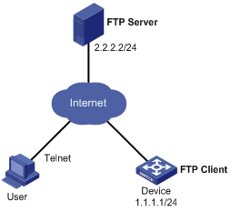
l The current software version is soft-version1, and Boot ROM version is bootrom-version1 for Device Immediately upgrade the software version and Boot ROM version of Device to soft-version2 and bootrom-version2 respectively through remote operations.
l The newest applications soft-version2.app and bootrom-version2.btm are both saved under the aaa directory of the FTP Server.
l The IP address of Device is 1.1.1.1/24, the IP address of the FTP Server is 2.2.2.2/24, and FTP Server is reachable.
l User has logged in to Device via Telnet and a route exists between User and Device.
Network diagram
Figure 1-1 Network diagram for remote upgrade
Configuration procedure
l Configuration on FTP Server (Note that configurations may vary with different types of servers)
# Enable FTP Server.
<FTP-Server> system-view
[FTP-Server] ftp server enable
# Set the FTP username to aaa and password to hello.
[FTP-Server] local-user aaa
[FTP-Server-luser-aaa] password cipher hello
# Configure the user to have access to the aaa directory.
[FTP-Server-luser-aaa] service-type ftp
[FTP-Server-luser-aaa] work-directory flash:/aaa
l Configuration on Device
![]()
If the size of the Flash on the device is not large enough, delete the original application programs from the Flash before downloading.
# Before upgrade, execute the save command to save the current configuration (configuration procedure is omitted).
# Log in to FTP Server (note that the prompt may vary with servers.)
<Device> ftp 2.2.2.2
Trying 2.2.2.2 ...
Press CTRL+K to abort
Connected to 2.2.2.2.
220 WFTPD 2.0 service (by Texas Imperial Software) ready for new user
User(2.2.2.2:(none)):aaa
331 Give me your password, please
Password:
230 Logged in successfully
[ftp]
# Download the soft-version2.app and bootrom-version2.btm programs on FTP Server to the Flash of Device.
[ftp] binary
[ftp] get soft-version2.app
[ftp] get bootrom-version2.btm
[ftp] bye
<Device>
# Upgrade the Boot ROM file of the AMB (resides in slot 0).
<Device> bootrom update file bootrom-version2.btm slot 0
# Upgrade the Boot ROM file of the SMB (resides in slot 1).
<Device> copy bootrom-version2.btm slot1#flash:/bootrom-version2.btm
<Device> bootrom update file slot1#flash:/bootrom-version2.btm slot 1
# Specify the application program for the next boot on the AMB.
<Device> boot-loader file soft-version2.app slot 0 main
# Specify the application program for the next boot on the SMB.
<Device> copy soft-version2.app slot1#flash:/soft-version2.app
<Device> boot-loader file slot1#flash:/soft-version2.app slot 1 main
# Reboot the device. The software version is upgraded now.
<Device> reboot
0 minutes).
