- Table of Contents
-
- 08-System Volume
- 00-System Volume Organization
- 01-Login Configuration
- 02-Basic System Configuration
- 03-Device Management Configuration
- 04-File System Management Configuration
- 05-SNMP Configuration
- 06-RMON Configuration
- 07-MAC Address Table Management Configuration
- 08-System Maintaining and Debugging Configuration
- 09-Information Center Configuration
- 10-PoE Configuration
- 11-Track Configuration
- 12-NQA Configuration
- 13-NTP Configuration
- 14-VRRP Configuration
- 15-HA Configuration
- 16-Hotfix Configuration
- 17-GR Overview
- Related Documents
-
| Title | Size | Download |
|---|---|---|
| 01-Login Configuration | 436.02 KB |
Table of Contents
1 Logging In to an Ethernet Switch
Logging In to an Ethernet Switch
Introduction to User Interface
Common User Interface Configuration
2 Logging In Through the Console Port
Setting Up the Connection to the Console Port
Console Port Login Configuration
Console Port Login Configurations for Different Authentication Modes
Console Port Login Configuration with Authentication Mode Being None
Console Port Login Configuration with Authentication Mode Being Password
Console Port Login Configuration with Authentication Mode Being Scheme
3 Logging In Through Telnet/SSH
Telnet Configurations for Different Authentication Modes
Telnet Configuration with Authentication Mode Being None
Telnet Configuration with Authentication Mode Being Password
Telnet Configuration with Authentication Mode Being Scheme
Telnet Connection Establishment
Configuration on the Administrator Side
Configuration on the Switch Side
Modem Connection Establishment
Connection Establishment Using NMS
6 Specifying Source for Telnet Packets
Specifying Source IP address/Interface for Telnet Packets
Displaying the source IP address/Interface Specified for Telnet Packets
Controlling Telnet Users by Source IP Addresses
Controlling Telnet Users by Source and Destination IP Addresses
Controlling Telnet Users by Source MAC Addresses
Controlling Network Management Users by Source IP Addresses
Controlling Network Management Users by Source IP Addresses
When logging in to an Ethernet switch, go to these sections for information you are interested in:
l Logging In to an Ethernet Switch
l Introduction to User Interface
l Specifying Source for Telnet Packets
Logging In to an Ethernet Switch
You can log in to an H3C S7500E series Ethernet switch in one of the following ways:
l Logging In Through the Console Port
l Logging In Through Telnet/SSH
Introduction to User Interface
Supported User Interfaces
H3C S7500E series Ethernet switch supports two types of user interfaces: AUX and VTY.
Table 1-1 Description on user interface
|
User interface |
Applicable user |
Port used |
Description |
|
AUX |
Users logging in through the Console port |
Console port |
Each switch can accommodate one AUX user. |
|
VTY |
Telnet users and SSH users |
Ethernet port |
Each switch can accommodate up to five VTY users. |
![]()
As the AUX port and the Console port of a H3C series switch are the same one, you will be in the AUX user interface if you log in through this port.
User Interface Number
Two kinds of user interface index exist: absolute user interface index and relative user interface index.
1) The absolute user interface indexes are as follows:
l AUX user interface: 0
l VTY user interfaces: Numbered after AUX user interfaces and increases in the step of 1
2) A relative user interface index can be obtained by appending a number to the identifier of a user interface type. It is generated by user interface type. The relative user interface indexes are as follows:
l AUX user interface: AUX 0
l VTY user interfaces: VTY 0, VTY 1, VTY 2, and so on.
Common User Interface Configuration
Follow these steps to perform common user interface configuration:
|
To do… |
Use the command… |
Remarks |
|
Lock the current user interface |
lock |
Optional Execute this command in user view. A user interface is not locked by default. |
|
Specify to send messages to all user interfaces/a specified user interface |
send { all | number | type number } |
Optional Execute this command in user view. |
|
Disconnect a specified user interface |
free user-interface [ type ] number |
Optional Execute this command in user view. |
|
Enter system view |
system-view |
— |
|
Set the banner |
header { incoming | legal | login | shell | motd } text |
Optional |
|
Set a system name for the switch |
sysname string |
Optional |
|
Enter user interface view |
user-interface [ type ] first-number [ last-number ] |
— |
|
Define a shortcut key for aborting tasks |
escape-key { default | character } |
Optional The default shortcut key combination for aborting tasks is < Ctrl + C >. |
|
Set the history command buffer size |
history-command max-size value |
Optional The default history command buffer size is 10. That is, a history command buffer can store up to 10 commands by default. |
|
Set the timeout time for the user interface |
idle-timeout minutes [ seconds ] |
Optional The default timeout time of a user interface is 10 minutes. With the timeout time being 10 minutes, the connection to a user interface is terminated if no operation is performed in the user interface within 10 minutes. You can use the idle-timeout 0 command to disable the timeout function. |
|
Set the maximum number of lines the screen can contain |
screen-length screen-length |
Optional By default, the screen can contain up to 24 lines. You can use the screen-length 0 command to disable the function to display information in pages. |
|
Make terminal services available |
shell |
Optional By default, terminal services are available in all user interfaces. |
|
Set the display type of a terminal |
terminal type { ansi | vt100 } |
Optional By default, the terminal display type is ANSI. The device must use the same type of display as the terminal. If the terminal uses VT 100, the device should also use VT 100. |
|
Display the information about the current user interface/all user interfaces |
display users [ all ] |
You can execute this command in any view. |
|
Display the physical attributes and configuration of the current/a specified user interface |
display user-interface [ type number | number ] [ summary ] |
You can execute this command in any view. |
When logging in through the Console port, go to these sections for information you are interested in:
l Setting Up the Connection to the Console Port
l Console Port Login Configuration
l Console Port Login Configuration with Authentication Mode Being None
l Console Port Login Configuration with Authentication Mode Being Password
l Console Port Login Configuration with Authentication Mode Being Scheme
![]()
The default system name of an H3C S7500E series Ethernet switch is H3C, that is, the command line prompt is H3C. All the following examples take H3C as the command line prompt.
Introduction
To log in through the Console port is the most common way to log in to a switch. It is also the prerequisite to configure other login methods. By default, you can log in to an H3C S7500E series Ethernet switch through its Console port only.
To log in to an Ethernet switch through its Console port, the related configuration of the user terminal must be in accordance with that of the Console port.
Table 2-1 lists the default settings of a Console port.
Table 2-1 The default settings of a Console port
|
Setting |
Default |
|
Baud rate |
9,600 bps |
|
Flow control |
Off |
|
Check mode |
No check bit |
|
Stop bits |
1 |
|
Data bits |
8 |
After logging in to a switch, you can perform configuration for AUX users. Refer to Console Port Login Configuration for details.
Setting Up the Connection to the Console Port
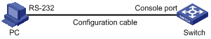
l Connect the serial port of your PC/terminal to the Console port of the switch, as shown in Figure 2-1.
Figure 2-1 Diagram for setting the connection to the Console port
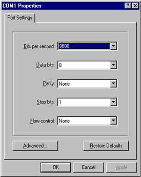
l If you use a PC to connect to the Console port, launch a terminal emulation utility (such as Terminal in Windows 3.X or HyperTerminal in Windows 9X/Windows 2000/Windows XP) and perform the configuration shown in Figure 2-2 through Figure 2-4 for the connection to be created. Normally, the parameters of a terminal are configured as those listed in Table 2-1.
Figure 2-2 Create a connection
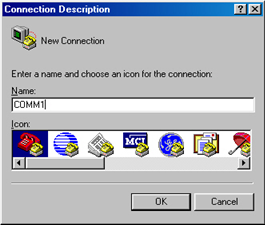
Figure 2-3 Specify the port used to establish the connection
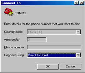
Figure 2-4 Set port parameters terminal window
l Turn on the switch. The user will be prompted to press the Enter key if the switch successfully completes POST (power-on self test). The prompt (such as <H3C>) appears after the user presses the Enter key.
l You can then configure the switch or check the information about the switch by executing commands. You can also acquire help by type the ? character. Refer to the following chapters for information about the commands.
Console Port Login Configuration
Common Configuration
Table 2-2 lists the common configuration of Console port login.
Table 2-2 Common configuration of Console port login
|
Configuration |
Description |
|
|
Console port configuration |
Baud rate |
Optional The default baud rate is 9,600 bps. |
|
Check mode |
Optional By default, the check mode of the Console port is set to “none”, which means no check bit. |
|
|
Stop bits |
Optional The default stop bits of a Console port is 1. |
|
|
Data bits |
Optional The default data bits of a Console port is 8. |
|
|
Flow control |
Optional The default is none, which disables flow control. |
|
|
AUX user interface configuration |
Configure the command level available to the users logging in to the AUX user interface |
Optional By default, commands of level 3 are available to the users logging in to the AUX user interface. |
|
Terminal configuration |
Define a shortcut key for aborting tasks |
Optional The default shortcut key combination for aborting tasks is < Ctrl + C >. |
|
Define a shortcut key for starting terminal sessions |
Optional By default, pressing Enter key starts the terminal session. |
|
|
Make terminal services available |
Optional By default, terminal services are available in all user interfaces |
|
|
Set the maximum number of lines the screen can contain |
Optional By default, the screen can contain up to 24 lines. |
|
|
Set history command buffer size |
Optional By default, the history command buffer can contain up to 10 commands. |
|
|
Set the timeout time of a user interface |
Optional The default timeout time is 10 minutes. |
|
![]()
Changing of Console port configuration terminates the connection to the Console port. To establish the connection again, you need to modify the configuration of the termination emulation utility running on your PC accordingly. Refer to Setting Up the Connection to the Console Port for details.
Console Port Login Configurations for Different Authentication Modes
Table 2-3 lists Console port login configurations for different authentication modes.
Table 2-3 Console port login configurations for different authentication modes
|
Authentication mode |
Console port login configuration |
Description |
|
|
None |
Perform common configuration |
Perform common configuration for Console port login |
Optional Refer to Common Configuration for details. |
|
Password |
Configure the password |
Configure the password for local authentication |
Required |
|
Perform common configuration |
Perform common configuration for Console port login |
Optional Refer to Common Configuration for details. |
|
|
Scheme |
Specify to perform local authentication or RADIUS authentication |
AAA configuration specifies whether to perform local authentication or RADIUS authentication |
Optional Local authentication is performed by default. Refer to the AAA Configuration in the Security Volume for details. |
|
Configure user name and password |
Configure user names and passwords for local/remote users |
Required l The user name and password of a local user are configured on the switch. l The user name and password of a remote user are configured on the RADIUS server. Refer to user manual of RADIUS server for details. |
|
|
Manage AUX users |
Set service type for AUX users |
Required |
|
|
Perform common configuration |
Perform common configuration for Console port login |
Optional Refer to Common Configuration for details. |
|
![]()
Changes of the authentication mode of Console port login will not take effect unless you exit and enter again the CLI.
Console Port Login Configuration with Authentication Mode Being None
Configuration Procedure
Follow these steps to perform Console port login configuration (with authentication mode being none):
|
To do… |
Use the command… |
Remarks |
|
|
Enter system view |
system-view |
— |
|
|
Enter AUX user interface view |
user-interface aux 0 |
— |
|
|
Configure not to authenticate users |
authentication-mode none |
Required By default, users logging in through the Console port are not authenticated. |
|
|
Configure the Console port |
Set the baud rate |
speed speed-value |
Optional The default baud rate of an AUX port (also the Console port) is 9,600 bps. |
|
Set the check mode |
parity { even | mark | none | odd | space } |
Optional By default, the check mode of a Console port is set to none, that is, no check bit. |
|
|
Set the stop bits |
stopbits { 1 | 1.5 | 2 } |
Optional The stop bits of a Console port is 1. |
|
|
Set the data bits |
databits { 5 | 6 | 7 | 8 } |
Optional The default data bits of a Console port is 8. |
|
|
Configure the command level available to users logging in to the user interface |
user privilege level level |
Optional By default, commands of level 3 are available to users logging in to the AUX user interface. |
|
|
Define a shortcut key for starting terminal sessions |
activation-key character |
Optional By default, pressing Enter key starts the terminal session. |
|
|
Define a shortcut key for aborting tasks |
escape-key { default | character } |
Optional The default shortcut key combination for aborting tasks is < Ctrl + C >. |
|
|
Make terminal services available |
shell |
Optional By default, terminal services are available in all user interfaces. |
|
|
Set the maximum number of lines the screen can contain |
screen-length screen-length |
Optional By default, the screen can contain up to 24 lines. You can use the screen-length 0 command to disable the function to display information in pages. |
|
|
Set the history command buffer size |
history-command max-size value |
Optional The default history command buffer size is 10. That is, a history command buffer can store up to 10 commands by default. |
|
|
Set the timeout time for the user interface |
idle-timeout minutes [ seconds ] |
Optional The default timeout time of a user interface is 10 minutes. With the timeout time being 10 minutes, the connection to a user interface is terminated if no operation is performed in the user interface within 10 minutes. You can use the idle-timeout 0 command to disable the timeout function. |
|
Note that if you configure not to authenticate the users, the command level available to users logging in to a switch depends on both the authentication-mode none command and the user privilege level level command, as listed in the following table.
Table 2-4 Determine the command level (A)
|
Scenario |
Command level |
||
|
Authentication mode |
User type |
Command |
|
|
None (authentication-mode none) |
Users logging in through Console ports |
The user privilege level level command not executed |
Level 3 |
|
The user privilege level level command already executed |
Determined by the level argument |
||
Configuration Example
Network requirements
Assume the switch is configured to allow you to login through Telnet, and your user level is set to the administrator level (level 3). After you telnet to the switch, you need to limit the console user at the following aspects.
l The user is not authenticated when logging in through the Console port.
l Commands of level 2 are available to user logging in to the AUX user interface.
l The baud rate of the Console port is 19200 bps.
l The screen can contain up to 30 lines.
l The history command buffer can contain up to 20 commands.
l The timeout time of the AUX user interface is 6 minutes.
Network diagram
Figure 2-5 Network diagram for AUX user interface configuration (with the authentication mode being none)
Configuration procedure
# Enter system view.
<H3C> system-view
# Enter AUX user interface view.
[H3C] user-interface aux 0
# Specify not to authenticate the user logging in through the Console port.
[H3C-ui-aux0] authentication-mode none
# Specify commands of level 2 are available to the user logging in to the AUX user interface.
[H3C-ui-aux0] user privilege level 2
# Set the baud rate of the Console port to 19200 bps.
[H3C-ui-aux0] speed 19200
# Set the maximum number of lines the screen can contain to 30.
[H3C-ui-aux0] screen-length 30
# Set the maximum number of commands the history command buffer can store to 20.
[H3C-ui-aux0] history-command max-size 20
# Set the timeout time of the AUX user interface to 6 minutes.
[H3C-ui-aux0] idle-timeout 6
After the above configuration, to ensure a successful login, the console user needs to change the corresponding configuration of the terminal emulation program running on the PC, to make the configuration consistent with that on the switch. Refer to Setting Up the Connection to the Console Port for details.
Console Port Login Configuration with Authentication Mode Being Password
Configuration Procedure
Follow these steps to perform Console port login configuration (with authentication mode being password):
|
To do… |
Use the command… |
Remarks |
|
|
Enter system view |
system-view |
— |
|
|
Enter AUX user interface view |
user-interface aux 0 |
— |
|
|
Configure to authenticate users using the local password |
authentication-mode password |
Required By default, users logging in through the Console port are not authenticated, while users logging in through the Modem or Telnet need to pass the password authentication. |
|
|
Set the local password |
set authentication password { cipher | simple } password |
Required |
|
|
Configure the Console port |
Set the baud rate |
speed speed-value |
Optional The default baud rate of an AUX port (also the Console port) is 9,600 bps. |
|
Set the check mode |
parity { even | mark | none | odd | space } |
Optional By default, the check mode of a Console port is set to none, that is, no check bit. |
|
|
Set the stop bits |
stopbits { 1 | 1.5 | 2 } |
Optional The default stop bits of a Console port is 1. |
|
|
Set the data bits |
databits { 5 | 6 | 7 | 8 } |
Optional The default data bits of a Console port is 8. |
|
|
Configure the command level available to users logging in to the user interface |
user privilege level level |
Optional By default, commands of level 3 are available to users logging in to the AUX user interface. |
|
|
Define a shortcut key for starting terminal sessions |
activation-key character |
Optional By default, pressing Enter key starts the terminal session. |
|
|
Define a shortcut key for aborting tasks |
escape-key { default | character } |
Optional The default shortcut key combination for aborting tasks is < Ctrl + C >. |
|
|
Make terminal services available to the user interface |
shell |
Optional By default, terminal services are available in all user interfaces. |
|
|
Set the maximum number of lines the screen can contain |
screen-length screen-length |
Optional By default, the screen can contain up to 24 lines. You can use the screen-length 0 command to disable the function to display information in pages. |
|
|
Set history command buffer size |
history-command max-size value |
Optional The default history command buffer size is 10. That is, a history command buffer can store up to 10 commands by default. |
|
|
Set the timeout time for the user interface |
idle-timeout minutes [ seconds ] |
Optional The default timeout time of a user interface is 10 minutes. With the timeout time being 10 minutes, the connection to a user interface is terminated if no operation is performed in the user interface within 10 minutes. You can use the idle-timeout 0 command to disable the timeout function. |
|
Note that if you configure to authenticate the users in the password mode, the command level available to users logging in to a switch depends on both the authentication-mode password and the user privilege level level command, as listed in the following table.
Table 2-5 Determine the command level (B)
|
Scenario |
Command level |
||
|
Authentication mode |
User type |
Command |
|
|
Local authentication (authentication-mode password) |
Users logging in to the AUX user interface |
The user privilege level level command not executed |
Level 3 |
|
The user privilege level level command already executed |
Determined by the level argument |
||
Configuration Example
Network requirements
Assume the switch is configured to allow you to login through Telnet, and your user level is set to the administrator level (level 3). After you telnet to the switch, you need to limit the Console user at the following aspects.
l The user is authenticated against the local password when logging in through the Console port.
l The local password is set to 123456 (in plain text).
l The commands of level 2 are available to users logging in to the AUX user interface.
l The baud rate of the Console port is 19,200 bps.
l The screen can contain up to 30 lines.
l The history command buffer can store up to 20 commands.
l The timeout time of the AUX user interface is 6 minutes.
Network diagram
Figure 2-6 Network diagram for AUX user interface configuration (with the authentication mode being password)
Configuration procedure
# Enter system view.
<H3C> system-view
# Enter AUX user interface view.
[H3C] user-interface aux 0
# Specify to authenticate the user logging in through the Console port using the local password.
[H3C-ui-aux0] authentication-mode password
# Set the local password to 123456 (in plain text).
[H3C-ui-aux0] set authentication password simple 123456
# Specify commands of level 2 are available to the user logging in to the AUX user interface.
[H3C-ui-aux0] user privilege level 2
# Set the baud rate of the Console port to 19200 bps.
[H3C-ui-aux0] speed 19200
# Set the maximum number of lines the screen can contain to 30.
[H3C-ui-aux0] screen-length 30
# Set the maximum number of commands the history command buffer can store to 20.
[H3C-ui-aux0] history-command max-size 20
# Set the timeout time of the AUX user interface to 6 minutes.
[H3C-ui-aux0] idle-timeout 6
After the above configuration, to ensure a successful login, the console user needs to change the corresponding configuration of the terminal emulation program running on the PC, to make the configuration consistent with that on the switch. Refer to Setting Up the Connection to the Console Port for details.
Console Port Login Configuration with Authentication Mode Being Scheme
Configuration Procedure
Follow these steps to perform Console port login configuration (with authentication mode being scheme):
|
To do… |
Use the command… |
Remarks |
||
|
Enter system view |
system-view |
— |
||
|
Configure the authentication mode |
Enter the default ISP domain view |
domain domain name |
Optional By default, the local AAA scheme is applied. If you specify to apply the local AAA scheme, you need to perform the configuration concerning local user as well. If you specify to apply an existing scheme by providing the radius-scheme-name argument, you need to perform the following configuration as well: l Perform AAA-RADIUS configuration on the switch. (Refer to AAA Configuration in the Security Volume for details.) l Configure the user name and password accordingly on the AAA server. (Refer to the user manual of AAA server.) |
|
|
Specify the AAA scheme to be applied to the domain |
authentication default { hwtacacs- scheme hwtacacs-scheme-name [ local ] | local | none | radius-scheme radius-scheme-name [ local ] } |
|||
|
Quit to system view |
quit |
|||
|
Create a local user (Enter local user view.) |
local-user user-name |
Required No local user exists by default. |
||
|
Set the authentication password for the local user |
password { simple | cipher } password |
Required |
||
|
Specify the service type for AUX users |
service-type terminal [ level level ] |
Required |
||
|
Quit to system view |
quit |
— |
||
|
Enter AUX user interface view |
user-interface aux 0 |
— |
||
|
Configure to authenticate users locally or remotely |
authentication-mode scheme [ command- authorization ] |
Required The specified AAA scheme determines whether to authenticate users locally or remotely. Users are authenticated locally by default. |
||
|
Configure the Console port |
Set the baud rate |
speed speed-value |
Optional The default baud rate of the AUX port (also the Console port) is 9,600 bps. |
|
|
Set the check mode |
parity { even | mark | none | odd | space } |
Optional By default, the check mode of a Console port is set to none, that is, no check bit. |
||
|
Set the stop bits |
stopbits { 1 | 1.5 | 2 } |
Optional The default stop bits of a Console port is 1. |
||
|
Set the data bits |
databits { 5 | 6 | 7 | 8 } |
Optional The default data bits of a Console port is 8. |
||
|
Configure the command level available to users logging in to the user interface |
user privilege level level |
Optional By default, commands of level 3 are available to users logging in to the AUX user interface. |
||
|
Define a shortcut key for starting terminal sessions |
activation-key character |
Optional By default, pressing Enter key starts the terminal session. |
||
|
Define a shortcut key for aborting tasks |
escape-key { default | character } |
Optional The default shortcut key combination for aborting tasks is < Ctrl + C >. |
||
|
Make terminal services available to the user interface |
shell |
Optional By default, terminal services are available in all user interfaces. |
||
|
Set the maximum number of lines the screen can contain |
screen-length screen-length |
Optional By default, the screen can contain up to 24 lines. You can use the screen-length 0 command to disable the function to display information in pages. |
||
|
Set history command buffer size |
history-command max-size value |
Optional The default history command buffer size is 10. That is, a history command buffer can store up to 10 commands by default. |
||
|
Set the timeout time for the user interface |
idle-timeout minutes [ seconds ] |
Optional The default timeout time of a user interface is 10 minutes. With the timeout time being 10 minutes, the connection to a user interface is terminated if no operation is performed in the user interface within 10 minutes. You can use the idle-timeout 0 command to disable the timeout function. |
||
Note that the level the commands of which are available to users logging in to a switch depends on the authentication-mode scheme [ command-authorization ] command, the user privilege level level command, and the service-type terminal [ level level ] command, as listed in Table 2-6.
Table 2-6 Determine the command level
|
Scenario |
Command level |
||
|
Authentication mode |
User type |
Command |
|
|
authentication-mode scheme [ command- authorization ] |
Users logging in to the Console port and pass AAA-RADIUS or local authentication |
The user privilege level level command is not executed, and the service-type terminal [ level level ] command does not specify the available command level. |
Level 0 The default command level available for local users is level 0. |
|
The user privilege level level command is not executed, and the service-type terminal [ level level ] command specifies the available command level. |
Determined by the service-type terminal [ level level ] command |
||
|
The user privilege level level command is executed, and the service-type terminal [ level level ] command does not specify the available command level. |
Level 0 |
||
|
The user privilege level level command is executed, and the service-type terminal [ level level ] command specifies the available command level. |
Determined by the service-type terminal [ level level ] command |
||
Configuration Example
Network requirements
Assume the switch is configured to allow you to login through Telnet, and your user level is set to the administrator level (level 3). After you telnet to the switch, you need to limit the console user at the following aspects.
l Configure the name of the local user to be “guest”.
l Set the authentication password of the local user to 123456 (in plain text).
l Set the service type of the local user to Terminal.
l Configure to authenticate the user logging in through the Console port in the scheme mode.
l The commands of level 2 are available to the user logging in to the AUX user interface.
l The baud rate of the Console port is 19,200 bps.
l The screen can contain up to 30 lines.
l The history command buffer can store up to 20 commands.
l The timeout time of the AUX user interface is 6 minutes.
Network diagram
Figure 2-7 Network diagram for AUX user interface configuration (with the authentication mode being scheme)
Configuration procedure
# Enter system view.
<H3C> system-view
# Create a local user named guest and enter local user view.
[H3C] local-user guest
# Set the authentication password to 123456 (in plain text).
[H3C-luser-guest] password simple 123456
# Set the service type to Terminal, Specify commands of level 2 are available to the user logging in to the AUX user interface.
[H3C-luser-guest] service-type terminal level 2
[H3C-luser-guest] quit
# Enter AUX user interface view.
[H3C] user-interface aux 0
# Configure to authenticate the user logging in through the Console port in the scheme mode.
[H3C-ui-aux0] authentication-mode scheme
# Set the baud rate of the Console port to 19200 bps.
[H3C-ui-aux0] speed 19200
# Set the maximum number of lines the screen can contain to 30.
[H3C-ui-aux0] screen-length 30
# Set the maximum number of commands the history command buffer can store to 20.
[H3C-ui-aux0] history-command max-size 20
# Set the timeout time of the AUX user interface to 6 minutes.
[H3C-ui-aux0] idle-timeout 6
After the above configuration, to ensure a successful login, the console user needs to change the corresponding configuration of the terminal emulation program running on the PC, to make the configuration consistent with that on the switch. Refer to Setting Up the Connection to the Console Port for details.
Logging In Through Telnet
When logging in through Telnet, go to these sections for information you are interested in:
l Telnet Configuration with Authentication Mode Being None
l Telnet Configuration with Authentication Mode Being Password
l Telnet Configuration with Authentication Mode Being Scheme
l Telnet Connection Establishment
Introduction
You can telnet to a remote switch to manage and maintain the switch. To achieve this, you need to configure both the switch and the Telnet terminal properly.
Table 3-1 Requirements for Telnet to a switch
|
Item |
Requirement |
|
Switch |
Start the Telnet Server |
|
The IP address of the VLAN of the switch is configured and the route between the switch and the Telnet terminal is available. |
|
|
The authentication mode and other settings are configured. Refer to Table 3-2 and Table 3-3. |
|
|
Telnet terminal |
Telnet is running. |
|
The IP address of the management VLAN of the switch is available. |
Common Configuration
Table 3-2 lists the common Telnet configuration.
Table 3-2 Common Telnet configuration
|
Configuration |
Remarks |
|
|
VTY user interface configuration |
Configure the command level available to users logging in to the VTY user interface |
Optional By default, commands of level 0 are available to users logging in to a VTY user interface. |
|
Configure the protocols the user interface supports |
Optional By default, Telnet and SSH protocol are supported. |
|
|
Set the command that is automatically executed when a user logs into the user interface |
Optional By default, no command is automatically executed when a user logs into a user interface. |
|
|
VTY terminal configuration |
Define a shortcut key for aborting tasks |
Optional The default shortcut key combination for aborting tasks is < Ctrl + C >. |
|
Make terminal services available |
Optional By default, terminal services are available in all user interfaces |
|
|
Set the maximum number of lines the screen can contain |
Optional By default, the screen can contain up to 24 lines. |
|
|
Set history command buffer size |
Optional By default, the history command buffer can contain up to 10 commands. |
|
|
Set the timeout time of a user interface |
Optional The default timeout time is 10 minutes. |
|
![]()
l The auto-execute command command may cause you unable to perform common configuration in the user interface, so use it with caution.
l Before executing the auto-execute command command and save your configuration, make sure you can log in to the switch in other modes and cancel the configuration.
Telnet Configurations for Different Authentication Modes
Table 3-3 lists Telnet configurations for different authentication modes.
Table 3-3 Telnet configurations for different authentication modes
|
Authentication mode |
Telnet configuration |
Remarks |
|
|
None |
Perform common configuration |
Perform common Telnet configuration |
Optional Refer to Table 3-2. |
|
Password |
Configure the password |
Configure the password for local authentication |
Required |
|
Perform common configuration |
Perform common Telnet configuration |
Optional Refer to Table 3-2. |
|
|
Scheme |
Specify to perform local authentication or RADIUS authentication |
AAA configuration specifies whether to perform local authentication or RADIUS authentication |
Optional Local authentication is performed by default. Refer to AAA Configuration in the Security Volume for details. |
|
Configure user name and password |
Configure user names and passwords for local/remote users |
Required l The user name and password of a local user are configured on the switch. l The user name and password of a remote user are configured on the RADIUS server. Refer to user manual of RADIUS server for details. |
|
|
Manage VTY users |
Set service type for VTY users |
Required |
|
|
Perform common configuration |
Perform common Telnet configuration |
Optional Refer to Table 3-2. |
|
Telnet Configuration with Authentication Mode Being None
Configuration Procedure
Follow these steps to perform Telnet configuration (with authentication mode being none):
|
To do… |
Use the command… |
Remarks |
|
Enter system view |
system-view |
— |
|
Enter one or more VTY user interface views |
user-interface vty first-number [ last-number ] |
— |
|
Configure not to authenticate users logging in to VTY user interfaces |
authentication-mode none |
Required By default, VTY users are authenticated after logging in. |
|
Configure the command level available to users logging in to VTY user interface |
user privilege level level |
Optional By default, commands of level 0 are available to users logging in to VTY user interfaces. |
|
Configure the protocols to be supported by the VTY user interface |
protocol inbound { all | ssh | telnet } |
Optional By default, both Telnet protocol and SSH protocol are supported. |
|
Set the command that is automatically executed when a user logs into the user interface |
auto-execute command text |
Optional By default, no command is automatically executed when a user logs into a user interface. |
|
Define a shortcut key for aborting tasks |
escape-key { default | character } |
Optional The default shortcut key combination for aborting tasks is < Ctrl + C >. |
|
Make terminal services available |
shell |
Optional By default, terminal services are available in all user interfaces. |
|
Set the maximum number of lines the screen can contain |
screen-length screen-length |
Optional By default, the screen can contain up to 24 lines. You can use the screen-length 0 command to disable the function to display information in pages. |
|
Set the history command buffer size |
history-command max-size value |
Optional The default history command buffer size is 10. That is, a history command buffer can store up to 10 commands by default. |
|
Set the timeout time of the VTY user interface |
idle-timeout minutes [ seconds ] |
Optional The default timeout time of a user interface is 10 minutes. With the timeout time being 10 minutes, the connection to a user interface is terminated if no operation is performed in the user interface within 10 minutes. You can use the idle-timeout 0 command to disable the timeout function. |
Note that if you configure not to authenticate the users, the command level available to users logging in to a switch depends on both the authentication-mode none command and the user privilege level level command, as listed in Table 3-4.
Table 3-4 Determine the command level when users logging in to switches are not authenticated
|
Scenario |
Command level |
||
|
Authentication mode |
User type |
Command |
|
|
None (authentication-mode none) |
VTY users |
The user privilege level level command not executed |
Level 0 |
|
The user privilege level level command already executed |
Determined by the level argument |
||
Configuration Example
1) Network requirements
Assume that you are a level 3 AUX user and want to perform the following configuration for Telnet users logging in to VTY 0:
l Do not authenticate users logging in to VTY 0.
l Commands of level 2 are available to users logging in to VTY 0.
l Telnet protocol is supported.
l The screen can contain up to 30 lines.
l The history command buffer can contain up to 20 commands.
l The timeout time of VTY 0 is 6 minutes.
2) Network diagram
Figure 3-1 Network diagram for Telnet configuration (with the authentication mode being none)
3) Configuration procedure
# Enter system view, and enable the Telnet service.
<H3C> system-view
[H3C] telnet server enable
# Enter VTY 0 user interface view.
[H3C] user-interface vty 0
# Configure not to authenticate Telnet users logging in to VTY 0.
[H3C-ui-vty0] authentication-mode none
# Specify commands of level 2 are available to users logging in to VTY 0.
[H3C-ui-vty0] user privilege level 2
# Configure Telnet protocol is supported.
[H3C-ui-vty0] protocol inbound telnet
# Set the maximum number of lines the screen can contain to 30.
[H3C-ui-vty0] screen-length 30
# Set the maximum number of commands the history command buffer can store to 20.
[H3C-ui-vty0] history-command max-size 20
# Set the timeout time to 6 minutes.
[H3C-ui-vty0] idle-timeout 6
Telnet Configuration with Authentication Mode Being Password
Configuration Procedure
Follow these steps to perform Telnet configuration (with authentication mode being password):
|
To do… |
Use the command… |
Remarks |
|
Enter system view |
system-view |
— |
|
Enter one or more VTY user interface views |
user-interface vty first-number [ last-number ] |
— |
|
Configure to authenticate users logging in to VTY user interfaces using the local password |
authentication-mode password |
Required |
|
Set the local password |
set authentication password { cipher | simple } password |
Required |
|
Configure the command level available to users logging in to the user interface |
user privilege level level |
Optional By default, commands of level 0 are available to users logging in to VTY user interface. |
|
Configure the protocol to be supported by the user interface |
protocol inbound { all | ssh | telnet } |
Optional By default, both Telnet protocol and SSH protocol are supported. |
|
Set the command that is automatically executed when a user logs into the user interface |
auto-execute command text |
Optional By default, no command is automatically executed when a user logs into a user interface. |
|
Define a shortcut key for aborting tasks |
escape-key { default | character } |
Optional The default shortcut key combination for aborting tasks is < Ctrl + C >. |
|
Make terminal services available |
shell |
Optional By default, terminal services are available in all user interfaces. |
|
Set the maximum number of lines the screen can contain |
screen-length screen-length |
Optional By default, the screen can contain up to 24 lines. You can use the screen-length 0 command to disable the function to display information in pages. |
|
Set the history command buffer size |
history-command max-size value |
Optional The default history command buffer size is 10. That is, a history command buffer can store up to 10 commands by default. |
|
Set the timeout time of the user interface |
idle-timeout minutes [ seconds ] |
Optional The default timeout time of a user interface is 10 minutes. With the timeout time being 10 minutes, the connection to a user interface is terminated if no operation is performed in the user interface within 10 minutes. You can use the idle-timeout 0 command to disable the timeout function. |
Note that if you configure to authenticate the users in the password mode, the command level available to users logging in to a switch depends on both the authentication-mode password command and the user privilege level level command, as listed in Table 3-5.
Table 3-5 Determine the command level when users logging in to switches are authenticated in the password mode
|
Scenario |
Command level |
||
|
Authentication mode |
User type |
Command |
|
|
Password (authentication-mode password) |
VTY users |
The user privilege level level command not executed |
Level 0 |
|
The user privilege level level command already executed |
Determined by the level argument |
||
Configuration Example
Network requirements
Assume that you are a level 3 AUX user and want to perform the following configuration for Telnet users logging in to VTY 0:
l Authenticate users logging in to VTY 0 using the local password.
l Set the local password to 123456 (in plain text).
l Commands of level 2 are available to users logging in to VTY 0.
l Telnet protocol is supported.
l The screen can contain up to 30 lines.
l The history command buffer can contain up to 20 commands.
l The timeout time of VTY 0 is 6 minutes.
Network diagram
Figure 3-2 Network diagram for Telnet configuration (with the authentication mode being password)
Configuration procedure
# Enter system view, and enable the Telnet service.
<H3C> system-view
[H3C] telnet server enable
# Enter VTY 0 user interface view.
[H3C] user-interface vty 0
# Configure to authenticate users logging in to VTY 0 using the local password.
[H3C-ui-vty0] authentication-mode password
# Set the local password to 123456 (in plain text).
[H3C-ui-vty0] set authentication password simple 123456
# Specify commands of level 2 are available to users logging in to VTY 0.
[H3C-ui-vty0] user privilege level 2
# Configure Telnet protocol is supported.
[H3C-ui-vty0] protocol inbound telnet
# Set the maximum number of lines the screen can contain to 30.
[H3C-ui-vty0] screen-length 30
# Set the maximum number of commands the history command buffer can store to 20.
[H3C-ui-vty0] history-command max-size 20
# Set the timeout time to 6 minutes.
[H3C-ui-vty0] idle-timeout 6
Telnet Configuration with Authentication Mode Being Scheme
Configuration Procedure
Follow these steps to perform Telnet configuration (with authentication mode being scheme):
|
To do… |
Use the command… |
Remarks |
|
|
Enter system view |
system-view |
— |
|
|
Configure the authentication scheme |
Enter the default ISP domain view |
domain domain name |
Optional By default, the local AAA scheme is applied. If you specify to apply the local AAA scheme, you need to perform the configuration concerning local user as well. If you specify to apply an existing scheme by providing the radius-scheme-name argument, you need to perform the following configuration as well: l Perform AAA-RADIUS configuration on the switch. (Refer to AAA Configuration in the Security Volume for details.) l Configure the user name and password accordingly on the AAA server. (Refer to the user manual of AAA server.) |
|
Configure the AAA scheme to be applied to the domain |
authentication default { hwtacacs-scheme hwtacacs-scheme- name [ local ] | local | none | radius-scheme radius-scheme-name [ local ] } |
||
|
Quit to system view |
quit |
||
|
Create a local user and enter local user view |
local-user user-name |
No local user exists by default. |
|
|
Set the authentication password for the local user |
password { simple | cipher } password |
Required |
|
|
Specify the service type for VTY users |
service-type telnet [ level level ] |
Required |
|
|
Quit to system view |
quit |
— |
|
|
Enter one or more VTY user interface views |
user-interface vty first-number [ last-number ] |
— |
|
|
Configure to authenticate users locally or remotely |
authentication-mode scheme |
Required The specified AAA scheme determines whether to authenticate users locally or remotely. Users are authenticated locally by default. |
|
|
Configure the command level available to users logging in to the user interface |
user privilege level level |
Optional By default, commands of level 0 are available to users logging in to the VTY user interfaces. |
|
|
Configure the supported protocol |
protocol inbound { all | ssh | telnet } |
Optional Both Telnet protocol and SSH protocol are supported by default. |
|
|
Set the command that is automatically executed when a user logs into the user interface |
auto-execute command text |
Optional By default, no command is automatically executed when a user logs into a user interface. |
|
|
Define a shortcut key for aborting tasks |
escape-key { default | character } |
Optional The default shortcut key combination for aborting tasks is < Ctrl + C >. |
|
|
Make terminal services available |
shell |
Optional Terminal services are available in all use interfaces by default. |
|
|
Set the maximum number of lines the screen can contain |
screen-length screen-length |
Optional By default, the screen can contain up to 24 lines. You can use the screen-length 0 command to disable the function to display information in pages. |
|
|
Set history command buffer size |
history-command max-size value |
Optional The default history command buffer size is 10. That is, a history command buffer can store up to 10 commands by default. |
|
|
Set the timeout time for the user interface |
idle-timeout minutes [ seconds ] |
Optional The default timeout time of a user interface is 10 minutes. With the timeout time being 10 minutes, the connection to a user interface is terminated if no operation is performed in the user interface within 10 minutes. You can use the idle-timeout 0 command to disable the timeout function. |
|
Note that if you configure to authenticate the users in the scheme mode, the command level available to users logging in to a switch depends on the authentication-mode scheme [ command-authorization ] command, the user privilege level level command, and the service-type { ftp [ ftp-directory directory ] | lan-access | { ssh | telnet | terminal }* [ level level ] } command, as listed in Table 3-6.
Table 3-6 Determine the command level when users logging in to switches are authenticated in the scheme mode
|
Scenario |
Command level |
||
|
Authentication mode |
User type |
Command |
|
|
Scheme (authentication-mode scheme [ command-authorization ]) |
VTY users that are AAA-RADIUS authenticated or locally authenticated |
The user privilege level level command is not executed, and the service-type command does not specify the available command level. |
Level 0 |
|
The user privilege level level command is not executed, and the service-type command specifies the available command level. |
Determined by the service-type command |
||
|
The user privilege level level command is executed, and the service-type command does not specify the available command level. |
Level 0 |
||
|
The user privilege level level command is executed, and the service-type command specifies the available command level. |
Determined by the service-type command |
||
|
VTY users that are authenticated in the RSA mode of SSH |
The user privilege level level command is not executed, and the service-type command does not specify the available command level. |
Level 0 |
|
|
The user privilege level level command is not executed, and the service-type command specifies the available command level. |
|||
|
The user privilege level level command is executed, and the service-type command does not specify the available command level. |
Determined by the user privilege level level command |
||
|
The user privilege level level command is executed, and the service-type command specifies the available command level. |
|||
|
VTY users that are authenticated in the password mode of SSH |
The user privilege level level command is not executed, and the service-type command does not specify the available command level. |
Level 0 |
|
|
The user privilege level level command is not executed, and the service-type command specifies the available command level. |
Determined by the service-type command |
||
|
The user privilege level level command is executed, and the service-type command does not specify the available command level. |
Level 0 |
||
|
The user privilege level level command is executed, and the service-type command specifies the available command level. |
Determined by the service-type command |
||
![]()
Refer to AAA Configuration and SSH2.0 Configuration in the Security Volume for configuration about AAA, RADIUS and SSH..
Configuration Example
1) Network requirements
Assume that you are a level 3 AUX user and want to perform the following configuration for Telnet users logging in to VTY 0:
l Configure the name of the local user to be “guest”.
l Set the authentication password of the local user to 123456 (in plain text).
l Set the service type of VTY users to Telnet.
l Configure to authenticate users logging in to VTY 0 in scheme mode.
l The commands of level 2 are available to users logging in to VTY 0.
l Telnet protocol is supported in VTY 0.
l The screen can contain up to 30 lines.
l The history command buffer can store up to 20 commands.
l The timeout time of VTY 0 is 6 minutes.
2) Network diagram
Figure 3-3 Network diagram for Telnet configuration (with the authentication mode being scheme)
3) Configuration procedure
# Enter system view, and enable the Telnet service.
<H3C> system-view
[H3C] telnet server enable
# Create a local user named guest and enter local user view.
[H3C] local-user guest
# Set the authentication password of the local user to 123456 (in plain text).
[H3C-luser-guest] password simple 123456
# Set the service type to Telnet, Specify commands of level 2 are available to users logging in to VTY 0.
[H3C-luser-guest] service-type telnet level 2
# Enter VTY 0 user interface view.
[H3C] user-interface vty 0
# Configure to authenticate users logging in to VTY 0 in the scheme mode.
[H3C-ui-vty0] authentication-mode scheme
# Configure Telnet protocol is supported.
[H3C-ui-vty0] protocol inbound telnet
# Set the maximum number of lines the screen can contain to 30.
[H3C-ui-vty0] screen-length 30
# Set the maximum number of commands the history command buffer can store to 20.
[H3C-ui-vty0] history-command max-size 20
# Set the timeout time to 6 minutes.
[H3C-ui-vty0] idle-timeout 6
Telnet Connection Establishment
Telnetting to a Switch from a Terminal
You can telnet to a switch and then configure the switch if the interface of the management VLAN of the switch is assigned with an IP address. (By default, VLAN 1 is the management VLAN.)
Following are procedures to establish a Telnet connection to a switch:
Step 1: Log in to the switch through the Console port, enable the Telnet server function and assign an IP address to the management VLAN interface of the switch.
l Connect to the Console port. Refer to Setting Up the Connection to the Console Port.
l Execute the following commands in the terminal window to enable the Telnet server function and assign an IP address to the management VLAN interface of the switch.
# Enable the Telnet server function and configure the IP address of the management VLAN interface as 202.38.160.92, and .the subnet mask as 255.255.255.0.
<H3C> system-view
[H3C] telnet server enable
[H3C] interface vlan-interface 1
[H3C-Vlan-interface1] ip address 202.38.160.92 255.255.255.0
Step 2: Before Telnet users can log in to the switch, corresponding configurations should have been performed on the switch according to different authentication modes for them. Refer to Telnet Configuration with Authentication Mode Being None, Telnet Configuration with Authentication Mode Being Password, and Telnet Configuration with Authentication Mode Being Scheme for details. By default, Telnet users need to pass the password authentication to login.
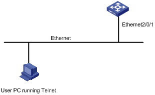
Step 3: Connect your PC to the Switch, as shown in Figure 3-4. Make sure the Ethernet port to which your PC is connected belongs to the management VLAN of the switch and the route between your PC and the switch is available.
Figure 3-4 Network diagram for Telnet connection establishment
Step 4: Launch Telnet on your PC, with the IP address of the management VLAN interface of the switch as the parameter, as shown in the following figure.
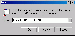
Step 5: Enter the password when the Telnet window displays “Login authentication” and prompts for login password. The CLI prompt (such as <H3C>) appears if the password is correct. If all VTY user interfaces of the switch are in use, you will fail to establish the connection and receive the message that says “All user interfaces are used, please try later!”. A H3C series Ethernet switch can accommodate up to five Telnet connections at same time.
Step 6: After successfully Telnetting to a switch, you can configure the switch or display the information about the switch by executing corresponding commands. You can also type ? at any time for help. Refer to the following chapters for the information about the commands.
![]()
l A Telnet connection will be terminated if you delete or modify the IP address of the VLAN interface in the Telnet session.
l By default, commands of level 0 are available to Telnet users authenticated by password. Refer to Basic System Configuration in the System Volume for information about command hierarchy.
Telnetting to Another Switch from the Current Switch
You can Telnet to another switch from the current switch. In this case, the current switch operates as the client, and the other operates as the server. If the interconnected Ethernet ports of the two switches are in the same LAN segment, make sure the IP addresses of the two management VLAN interfaces to which the two Ethernet ports belong to are of the same network segment, or the route between the two VLAN interfaces is available.
As shown in Figure 3-6, after Telnetting to a switch (labeled as Telnet client), you can Telnet to another switch (labeled as Telnet server) by executing the telnet command and then to configure the later.
Figure 3-6 Network diagram for Telnetting to another switch from the current switch

Step 1: Configure the user name and password for Telnet on the switch operating as the Telnet server. Refer to section Telnet Configuration with Authentication Mode Being None”, section Telnet Configuration with Authentication Mode Being Password, and Telnet Configuration with Authentication Mode Being Scheme for details. By default, Telnet users need to pass the password authentication to login.
Step 2: Telnet to the switch operating as the Telnet client.
Step 3: Execute the following command on the switch operating as the Telnet client:
<H3C> telnet xxxx
Where xxxx is the IP address or the host name of the switch operating as the Telnet server. You can use the ip host to assign a host name to a switch.
Step 4: Enter the password. If the password is correct, the CLI prompt (such as <H3C>) appears. If all VTY user interfaces of the switch are in use, you will fail to establish the connection and receive the message that says “All user interfaces are used, please try later!”.
Step 5: After successfully Telnetting to the switch, you can configure the switch or display the information about the switch by executing corresponding commands. You can also type ? at any time for help. Refer to the following chapters for the information about the commands.
Logging In Through SSH
Secure Shell (SSH) offers an approach to logging into a remote device securely. With encryption and strong authentication, it protects devices against attacks such as IP spoofing and plain text password interception. For the security features provided by SSH, see SSH Configuration in the Security Volume.
When logging in using modem, go to these sections for information you are interested in:
l Configuration on the Administrator Side
l Configuration on the Switch Side
l Modem Connection Establishment
l Modem Attribute Configuration
Introduction
You may log in your switch from its console port from a remote device across a PSTN with a pair of modems in between. When your switching network fails, this allows you to remotely configure your switch, retrieve logs and warning messages, and locate the problem.
To log in to your switch in this way, you need to configure the terminal and the switch properly, as listed in the following table.
Table 4-1 Requirements for logging in to a switch using a modem
|
Item |
Requirement |
|
Administrator side |
The PC can communicate with the modem connected to it. |
|
The modem is properly connected to PSTN. |
|
|
The telephone number of the switch side is available. |
|
|
Switch side |
The modem is connected to the Console port of the switch properly. |
|
The modem is properly configured. |
|
|
The modem is properly connected to PSTN and a telephone set. |
|
|
The authentication mode and other related settings are configured on the switch. Refer to Table 2-3. |
Configuration on the Administrator Side
The PC can communicate with the modem connected to it. The modem is properly connected to PSTN. And the telephone number of the switch side is available.
Configuration on the Switch Side
Modem Configuration
Perform the following configuration on the modem directly connected to the switch:
AT&F ----------------------- Restore the factory settings
ATS0=1 ----------------------- Configure to answer automatically after the first ring
AT&D ----------------------- Ignore DTR signal
AT&K0 ----------------------- Disable flow control
AT&R1 ----------------------- Ignore RTS signal
AT&S0 ----------------------- Set DSR to high level by force
ATEQ1&W ----------------------- Disable the modem from returning command response and the result, save the changes
You can verify your configuration by executing the AT&V command.
![]()
The above configuration is unnecessary to the modem on the administrator side.
The configuration commands and the output of different modems may differ. Refer to the user manual of the modem when performing the above configuration.
Switch Configuration
![]()
After logging in to a switch through its Console port by using a modem, you will enter the AUX user interface. The corresponding configuration on the switch is the same as those when logging in to the switch locally through its Console port except that:
l When you log in through the Console port using a modem, the baud rate of the Console port is usually set to a value lower than the transmission speed of the modem. Otherwise, packets may get lost.
l Other settings of the Console port, such as the check mode, the stop bits, and the data bits, remain the default.
The configuration on the switch depends on the authentication mode the user is in. Refer to Table 2-3 for the information about authentication mode configuration.
Configuration on switch when the authentication mode is none
Refer to Console Port Login Configuration with Authentication Mode Being None.
Configuration on switch when the authentication mode is password
Refer to Console Port Login Configuration with Authentication Mode Being Password.
Configuration on switch when the authentication mode is scheme
Refer to Console Port Login Configuration with Authentication Mode Being Scheme.
Modem Connection Establishment
Step 1: Configure the user name and password on the switch. Refer to Console Port Login Configuration with Authentication Mode Being None, Console Port Login Configuration with Authentication Mode Being Password, and Console Port Login Configuration with Authentication Mode Being Scheme for details.
Step 2: Perform the following configuration on the modem directly connected to the switch.
AT&F ----------------------- Restore the factory settings
ATS0=1 ----------------------- Configure to answer automatically after the first ring
AT&D ----------------------- Ignore DTR signal
AT&K0 ----------------------- Disable flow control
AT&R1 ----------------------- Ignore RTS signal
AT&S0 ----------------------- Set DSR to high level by force
ATEQ1&W ----------------------- Disable the modem from returning command response and the result, save the changes
You can verify your configuration by executing the AT&V command.
![]()
l The configuration commands and the output of different modems may differ. Refer to the user manual of the modem when performing the above configuration.
l It is recommended that the baud rate of the AUX port (also the Console port) be set to a value lower than the transmission speed of the modem. Otherwise, packets may get lost.
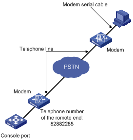
Step 3: Connect your PC, the modems, and the switch, as shown in the following figure.
Figure 4-1 Establish the connection by using modems
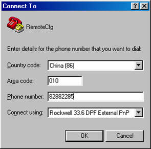
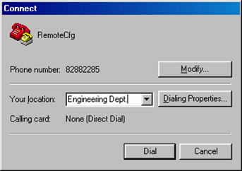
Step 4: Launch a terminal emulation utility on the PC and set the telephone number to call the modem directly connected to the switch, as shown in Figure 4-2 and Figure 4-3. Note that you need to set the telephone number to that of the modem directly connected to the switch.
Figure 4-2 Set the telephone number
Step 5: Provide the password when prompted. If the password is correct, the prompt (such as <H3C>) appears. You can then configure or manage the switch. You can also enter the character ? at anytime for help. Refer to the following chapters for information about the configuration commands.
![]()
If you perform no AUX user-related configuration on the switch, the commands of level 3 are available to modem users.
Modem Attribute Configuration
You can configure the attributes of the modem directly connected to the console port of your switch. This modem is called the switch-side modem.
Configuration Prerequisites
l The authentication mode for login users has been configured on the AUX user interface.
l The modem dialup configuration environment is ready.
Configuration Procedure
Follow these steps to configure the switch-side modem:
|
To do … |
Use the command … |
Remarks |
|
Enter system view |
system-view |
— |
|
Enter AUX user interface view |
user-interface aux 0 |
— |
|
Enable the modem to accept incoming calls, initiate outgoing calls, or both |
modem [ both | call-in | call-out ] |
Required |
|
Configure the modem to operate in the auto-answer mode |
modem auto-answer |
Optional Manual answer mode applies by default. |
|
Set the maximum amount of time that the modem waits for the carrier signal after the off-hook action during incoming call connection setup |
modem timer answer seconds |
Optional 30 seconds by default |
Configuration Example
Network requirements
Configure the switch-side modem to allow both incoming calls and outgoing calls, and configure the modem to operate in the auto-answer mode. Set the timeout time that the modem waits for the carrier signal after the off-hook action during incoming call connection setup to 45 seconds.
Network diagram
See Figure 4-1.
Configuration procedure
# Enter AUX user interface view.
<H3C> system-view
System View: return to User View with Ctrl+Z.
[H3C] user-interface aux 0
# Configure the modem to allow both incoming calls and outgoing calls.
[H3C-ui-aux0] modem both
# Configure the modem to operate in the auto-answer mode.
[H3C-ui-aux0] modem auto-answer
# Set the timeout time to 45 seconds.
[H3C-ui-aux0] modem timer answer 45
When logging in through NMS, go to these sections for information you are interested in:
l Connection Establishment Using NMS
Introduction
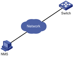
You can also log in to a switch through an NMS (network management station), and then configure and manage the switch through the agent module on the switch.
l The agent here refers to the software running on network devices (switches) and as the server.
l SNMP (simple network management protocol) is applied between the NMS and the agent.
To log in to a switch through an NMS, you need to perform related configuration on both the NMS and the switch.
Table 5-1 Requirements for logging in to a switch through an NMS
|
Item |
Requirement |
|
Switch |
The IP address of the management VLAN of the switch is configured. The route between the NMS and the switch is available. |
|
The basic SNMP functions are configured. (Refer to SNMP Configuration in the System Volume for details.) |
|
|
NMS |
The NMS is properly configured. (Refer to the user manual of the NMS for details.) |
Connection Establishment Using NMS
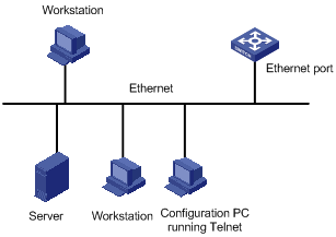
Figure 5-1 Network diagram for logging in through an NMS
When specifying source IP address/interface for Telnet packets, go to these sections for information you are interested in:
l Specifying Source IP address/Interface for Telnet Packets
l Displaying the source IP address/Interface Specified for Telnet Packets
Introduction
To improve security and make it easier to manage services, you can specify source IP addresses/interfaces for Telnet clients.
Usually, VLAN interface IP addresses and Loopback interface IP addresses are used as the source IP addresses of Telnet packets. After you specify the IP address of a VLAN interface or a Loopback interface as the source IP address of Telnet packets, all the packets exchanged between the Telnet client and the Telnet server use the IP address as their source IP addresses, regardless of the ports through which they are transmitted. In such a way, the actual IP addresses used are concealed. This helps to improve security. Specifying source IP address/interfaces for Telnet packets also provides a way to successfully connect to servers that only accept packets with specific source IP addresses.
Specifying Source IP address/Interface for Telnet Packets
The configuration can be performed in user view and system view. The configuration performed in user view only applies to the current session. Whereas the configuration performed in system view applies to all the subsequent sessions. Priority in user view is higher than that in system view.
Specifying source IP address/interface for Telnet packets in user view
Follow these steps to specify source IP address/interface for Telnet packets in user view:
|
To do… |
Use the command… |
Remarks |
|
Specify source IP address/interface for Telnet packets (the switch operates as a Telnet client) |
telnet remote-system [ port-number ] [ source { ip ip-address | interface interface-type interface-number } ] |
Optional By default, no source IP address/interface is specified. |
Specifying source IP address/interface for Telnet packets in system view
Follow these steps to specify source IP address/interface for Telnet packets in system view:
|
To do… |
Use the command… |
Remarks |
|
Enter system view |
system-view |
— |
|
Specify source IP address/interface for Telnet packets |
telnet client source { ip ip-address | interface interface-type interface-number } |
Optional By default, no source IP address/interface is specified. |
![]()
l The IP address specified must be a local IP address.
l When specifying the source interface for Telnet packets, make sure the interface already exists.
l Before specifying the source IP address/interface for Telnet packets, make sure the route between the interface and the Telnet server is reachable.
Displaying the source IP address/Interface Specified for Telnet Packets
Follow these steps to display the source IP address/interface specified for Telnet packets:
|
To do… |
Use the command… |
Remarks |
|
Display the source IP address/interface specified for Telnet packets |
display telnet client configuration |
Available in any view |
When controlling login users, go to these sections for information you are interested in:
l Controlling Network Management Users by Source IP Addresses
Introduction
Multiple ways are available for controlling different types of login users, as listed in Table 7-1.
Table 7-1 Ways to control different types of login users
|
Login mode |
Control method |
Implementation |
Related section |
|
Telnet |
By source IP addresses |
Through basic ACLs |
|
|
By source and destination IP addresses |
Through advanced ACLs |
Controlling Telnet Users by Source and Destination IP Addresses |
|
|
By source MAC addresses |
Through Layer 2 ACLs |
||
|
SNMP |
By source IP addresses |
Through basic ACLs |
Controlling Telnet Users
Prerequisites
The controlling policy against Telnet users is determined, including the source and destination IP addresses to be controlled and the controlling actions (permitting or denying).
Controlling Telnet Users by Source IP Addresses
This configuration needs to be implemented by basic ACL; a basic ACL ranges from 2000 to 2999. For the definition of ACL, refer to ACL Configuration in the Security Volume.
Follow these steps to control Telnet users by source IP addresses:
|
Use the command… |
Remarks |
|
|
Enter system view |
system-view |
— |
|
Create a basic ACL or enter basic ACL view |
acl [ ipv6 ] number acl-number [ match-order { config | auto } ] |
As for the acl number command, the config keyword is specified by default. |
|
Define rules for the ACL |
rule [ rule-id ] { permit | deny } [ source { sour-addr sour-wildcard | any } | time-range time-name | fragment | logging ]* |
Required |
|
Quit to system view |
quit |
— |
|
Enter user interface view |
user-interface [ type ] first-number [ last-number ] |
— |
|
Apply the ACL to control Telnet users by source IP addresses |
acl [ ipv6 ] acl-number { inbound | outbound } |
Required The inbound keyword specifies to filter the users trying to Telnet to the current switch. The outbound keyword specifies to filter users trying to Telnet to other switches from the current switch. |
Controlling Telnet Users by Source and Destination IP Addresses
This configuration needs to be implemented by advanced ACL; an advanced ACL ranges from 3000 to 3999. For the definition of ACL, refer to ACL Configuration in the Security Volume.
Follow these steps to control Telnet users by source and destination IP addresses:
|
To do… |
Use the command… |
Remarks |
|
Enter system view |
system-view |
— |
|
Create an advanced ACL or enter advanced ACL view |
acl [ ipv6 ] number acl-number [ match-order { config | auto } ] |
As for the acl number command, the config keyword is specified by default. |
|
Define rules for the ACL |
rule [ rule-id ] { permit | deny } rule-string |
Required You can define rules as needed to filter by specific source and destination IP addresses. |
|
Quit to system view |
quit |
— |
|
Enter user interface view |
user-interface [ type ] first-number [ last-number ] |
— |
|
Apply the ACL to control Telnet users by specified source and destination IP addresses |
acl [ ipv6 ] acl-number { inbound | outbound } |
Required The inbound keyword specifies to filter the users trying to Telnet to the current switch. The outbound keyword specifies to filter users trying to Telnet to other switches from the current switch. |
Controlling Telnet Users by Source MAC Addresses
This configuration needs to be implemented by Layer 2 ACL; a Layer 2 ACL ranges from 4000 to 4999. For the definition of ACL, refer to ACL Configuration in the Security Volume.
Follow these steps to control Telnet users by source MAC addresses:
|
To do… |
Use the command… |
Remarks |
|
Enter system view |
system-view |
— |
|
Create a basic ACL or enter basic ACL view |
acl number acl-number [ match-order { config | auto } ] |
As for the acl number command, the config keyword is specified by default. |
|
Define rules for the ACL |
rule [ rule-id ] { permit | deny } rule-string |
Required You can define rules as needed to filter by specific source MAC addresses. |
|
Quit to system view |
quit |
— |
|
Enter user interface view |
user-interface [ type ] first-number [ last-number ] |
— |
|
Apply the ACL to control Telnet users by source MAC addresses |
acl acl-number inbound |
Required The inbound keyword specifies to filter the users trying to Telnet to the current switch. |
![]()
Layer 2 ACL is invalid for this function if the source IP address of the Telnet client and the interface IP address of the Telnet server are not in the same subnet.
Configuration Example
Network requirements
Only the Telnet users sourced from the IP address of 10.110.100.52 and 10.110.100.46 are permitted to log in to the switch.
Network diagram
Figure 7-1 Network diagram for controlling Telnet users using ACLs
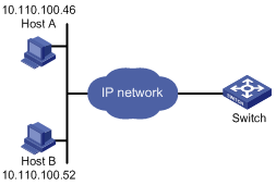
Configuration procedure
# Define a basic ACL.
<H3C> system-view
[H3C] acl number 2000 match-order config
[H3C-acl-basic-2000] rule 1 permit source 10.110.100.52 0
[H3C-acl-basic-2000] rule 2 permit source 10.110.100.46 0
[H3C-acl-basic-2000] rule 3 deny source any
[H3C-acl-basic-2000] quit
# Apply the ACL.
[H3C] user-interface vty 0 4
[H3C-ui-vty0-4] acl 2000 inbound
Controlling Network Management Users by Source IP Addresses
You can manage a H3C S7500E series Ethernet switch through network management software. Network management users can access switches through SNMP.
You need to perform the following two operations to control network management users by source IP addresses.
l Defining an ACL
l Applying the ACL to control users accessing the switch through SNMP
Prerequisites
The controlling policy against network management users is determined, including the source IP addresses to be controlled and the controlling actions (permitting or denying).
Controlling Network Management Users by Source IP Addresses
Follow these steps to control network management users by source IP addresses:
|
To do… |
Use the command… |
Remarks |
|
Enter system view |
system-view |
— |
|
Create a basic ACL or enter basic ACL view |
acl number acl-number [ match-order { config | auto } ] |
As for the acl number command, the config keyword is specified by default. |
|
Define rules for the ACL |
rule [ rule-id ] { permit | deny } [ source { sour-addr sour-wildcard | any } | time-range time-name | fragment | logging ]* |
Required |
|
Quit to system view |
quit |
— |
|
Apply the ACL while configuring the SNMP community name |
snmp-agent community { read | write } community-name [ mib-view view-name | acl acl-number ]* |
Required According to the SNMP version and configuration customs of NMS users, you can reference an ACL when configuring community name, group name or username. For the detailed configuration, refer to SNMP Configuration in the System Volume. |
|
Apply the ACL while configuring the SNMP group name |
snmp-agent group { v1 | v2c } group-name [ read-view read-view ] [ write-view write-view ] [ notify-view notify-view ] [ acl acl-number ] snmp-agent group v3 group-name [ authentication | privacy ] [ read-view read-view ] [ write-view write-view ] [ notify-view notify-view ] [ acl acl-number ] |
|
|
Apply the ACL while configuring the SNMP user name |
snmp-agent usm-user { v1 | v2c } user-name group-name [ acl acl-number ] snmp-agent usm-user v3 user-name group-name [ [ cipher ] authentication-mode { md5 | sha } auth-password [ privacy-mode { aes128 | des56 } priv-password ] ] [ acl acl-number ] |
Configuration Example
Network requirements
Only SNMP users sourced from the IP addresses of 10.110.100.52 and 10.110.100.46 are permitted to access the switch.
Network diagram
Figure 7-2 Network diagram for controlling SNMP users using ACLs
Configuration procedure
# Define a basic ACL.
<H3C> system-view
[H3C] acl number 2000 match-order config
[H3C-acl-basic-2000] rule 1 permit source 10.110.100.52 0
[H3C-acl-basic-2000] rule 2 permit source 10.110.100.46 0
[H3C-acl-basic-2000] rule 3 deny source any
[H3C-acl-basic-2000] quit
# Apply the ACL to only permit SNMP users sourced from the IP addresses of 10.110.100.52 and 10.110.100.46 to access the switch.
[H3C] snmp-agent community read h3c acl 2000
[H3C] snmp-agent group v2c h3cgroup acl 2000
[H3C] snmp-agent usm-user v2c h3cuser h3cgroup acl 2000
