- Table of Contents
-
- H3C S12500R Ethernet Switch Router Series Config Examples-Release 36xx-6W100
- 01-Login Management Configuration Examples
- 02-RBAC Configuration Examples
- 03-Software Upgrade Examples
- 04-Ethernet Link Aggregation Configuration Examples
- 05-Port Isolation Configuration Examples
- 06-Spanning Tree Configuration Examples
- 07-VLAN Configuration Examples
- 08-VLAN Tagging Configuration Examples
- 09-DHCP Snooping Configuration Examples
- 10-Cross-Subnet Dynamic IP Address Allocation Configuration Examples
- 11-IPv6 over IPv4 Tunneling with OSPFv3 Configuration Examples
- 12-GRE Tunnel Configuration Examples
- 13-GRE with OSPF Configuration Examples
- 14-OSPF Configuration Examples
- 15-IS-IS Configuration Examples
- 16-BGP Configuration Examples
- 17-Policy-Based Routing Configuration Examples
- 18-OSPFv3 Configuration Examples
- 19-IPv6 IS-IS Configuration Examples
- 20-Routing Policy Configuration Examples
- 21-IGMP Snooping Configuration Examples
- 22-IGMP Configuration Examples
- 23-MLD Snooping Configuration Examples
- 24-Basic MPLS Configuration Examples
- 25-MPLS L3VPN Configuration Examples
- 26-ACL Configuration Examples
- 27-Control Plane-Based QoS Policy Configuration Examples
- 28-Traffic Policing Configuration Examples
- 29-GTS and Rate Limiting Configuration Examples
- 30-Priority Mapping and Queue Scheduling Configuration Examples
- 31-Traffic Filtering Configuration Examples
- 32-AAA Configuration Examples
- 33-SSH Configuration Examples
- 34-IP Source Guard Configuration Examples
- 35-Ethernet OAM Configuration Examples
- 36-CFD Configuration Examples
- 37-DLDP Configuration Examples
- 38-VRRP Configuration Examples
- 39-BFD Configuration Examples
- 40-NTP Configuration Examples
- 41-SNMP Configuration Examples
- 42-NQA Configuration Examples
- 43-Mirroring Configuration Examples
- 44-sFlow Configuration Examples
- 45-OpenFlow Configuration Examples
- 46-MAC Address Table Configuration Examples
- 47-Static Multicast MAC Address Entry Configuration Examples
- 48-IP Unnumbered Configuration Examples
- 49-Congestion Avoidance and Queue Scheduling Configuration Examples
- 50-Attack Protection Configuration Examples
- 51-Smart Link Configuration Examples
- 52-RRPP Configuration Examples
- 53-BGP Route Selection Configuration Examples
- 54-IS-IS Route Summarization Configuration Examples
- 55-MPLS OAM Configuration Examples
- 56-MPLS TE Configuration Examples
- 57-VXLAN Configuration Examples
- 58-NetStream Configuration Examples
- 59-EVPN-DCI over an MPLS L3VPN Network Configuration Examples
- 60-PTP Configuration Examples
- 61-S-MLAG Configuration Examples
- 62-MPLS SR Configuration Examples
- 63-Puppet Configuration Examples
- Related Documents
-
| Title | Size | Download |
|---|---|---|
| 56-MPLS TE Configuration Examples | 147.07 KB |
|
|
|
H3C S12500R Switch Router Series |
|
MPLS TE Configuration Examples |
|
|
|
|
Copyright © 2021 New H3C Technologies Co., Ltd. All rights reserved.
No part of this manual may be reproduced or transmitted in any form or by any means without prior written consent of New H3C Technologies Co., Ltd.
Except for the trademarks of New H3C Technologies Co., Ltd., any trademarks that may be mentioned in this document are the property of their respective owners.
The information in this document is subject to change without notice.
Introduction
This document provides MPLS TE configuration examples.
Prerequisites
This document is not restricted to specific software or hardware versions.
The configuration examples in this document were created and verified in a lab environment, and all the devices were started with the factory default configuration. When you are working on a live network, make sure you understand the potential impact of every command on your network.
This document assumes that you have basic knowledge of MPLS TE.
Example: Establishing MPLS TE tunnels with RSVP-TE
Network configuration
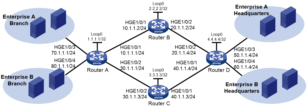
As shown in Figure 1, use RSVP-TE to establish two MPLS TE tunnels between Router A and Router D. The MPLS TE tunnel for Enterprise A requires a bandwidth of 20000 kbps. The MPLS TE tunnel for Enterprise B requires a bandwidth of 30000 kbps.
The maximum bandwidth of the link that each tunnel traverses is 50000 kbps and the maximum reservable bandwidth is 40000 kbps.
Analysis
To establish MPLS TE tunnels through RSVP-TE, you must perform the following tasks:
· Enable MPLS, MPLS TE, and RSVP-TE on nodes that the MPLS TE tunnels traverse.
· On each interface that the MPLS TE tunnels traverse, configure link TE attributes, including the maximum link bandwidth and the maximum reservable bandwidth.
· On each node that the MPLS TE tunnels traverse, configure the IGP TE extension to advertise the link TE attributes, which generates a TEDB on each node.
Based on the TEDB, CSPF calculates the shortest, TE constraints-compliant path to the tunnel destination. If you do not configure the IGP TE extension, the path is created based on IGP routing. The supported IGP TE extensions are OSPF TE and ISIS TE. This example uses OSPF TE.
· Create a tunnel interface on the ingress node of each MPLS TE tunnel, and perform the following tasks on the tunnel interface:
¡ Specify the tunnel destination address.
¡ Specify the tunnel bandwidth as required (20000 kbps for Enterprise A and 30000 kbps for Enterprise B).
¡ Specify the MPLS TE signaling protocol as RSVP-TE.
RSVP-TE advertises labels to establish CRLSPs and reserves bandwidth resources on each node along the calculated path.
· On the ingress node of each MPLS TE tunnel, configure static routing to direct traffic to the MPLS TE tunnel.
Software versions used
This configuration example was created and verified on Release 3606.
Restrictions and guidelines
By default, interfaces on the device are disabled (in ADM or Administratively Down state). To have an interface operate, you must use the undo shutdown command to enable that interface.
Before configuration, disable the spanning tree feature globally or map each VLAN to an MSTI.
Procedures
1. Configure IP addresses for interfaces:
# Configure IP addresses and masks for interfaces, including the loopback interface, as shown in Figure 1.
2. Configure OSPF to ensure IP connectivity among the switch routers:
# Configure Router A.
<RouterA> system-view
[RouterA] ospf
[RouterA-ospf-1] area 0
[RouterA-ospf-1-area-0.0.0.0] network 1.1.1.1 0.0.0.0
[RouterA-ospf-1-area-0.0.0.0] network 10.1.1.0 0.0.0.255
[RouterA-ospf-1-area-0.0.0.0] network 30.1.1.0 0.0.0.255
[RouterA-ospf-1-area-0.0.0.0] quit
[RouterA-ospf-1] quit
# Configure Router B.
<RouterB> system-view
[RouterB] ospf
[RouterB-ospf-1] area 0
[RouterB-ospf-1-area-0.0.0.0] network 2.2.2.2 0.0.0.0
[RouterB-ospf-1-area-0.0.0.0] network 10.1.1.0 0.0.0.255
[RouterB-ospf-1-area-0.0.0.0] network 20.1.1.0 0.0.0.255
[RouterB-ospf-1-area-0.0.0.0] quit
[RouterB-ospf-1] quit
# Configure Router C.
<RouterC> system-view
[RouterC] ospf
[RouterC-ospf-1] area 0
[RouterC-ospf-1-area-0.0.0.0] network 3.3.3.3 0.0.0.0
[RouterC-ospf-1-area-0.0.0.0] network 30.1.1.0 0.0.0.255
[RouterC-ospf-1-area-0.0.0.0] network 40.1.1.0 0.0.0.255
[RouterC-ospf-1-area-0.0.0.0] quit
[RouterC-ospf-1] quit
# Configure Router D.
<RouterD> system-view
[RouterD] ospf
[RouterD-ospf-1] area 0
[RouterD-ospf-1-area-0.0.0.0] network 4.4.4.4 0.0.0.0
[RouterD-ospf-1-area-0.0.0.0] network 20.1.1.0 0.0.0.255
[RouterD-ospf-1-area-0.0.0.0] network 40.1.1.0 0.0.0.255
[RouterD-ospf-1-area-0.0.0.0] quit
[RouterD-ospf-1] quit
# Execute the display ip routing-table command on each switch to verify that the switches have learned the routes to one another, including the routes to the loopback interfaces. The following shows the output on Router A.
[RouterA] display ip routing-table
Destinations : 21 Routes : 21
Destination/Mask Proto Pre Cost NextHop Interface
0.0.0.0/32 Direct 0 0 127.0.0.1 InLoop0
1.1.1.1/32 Direct 0 0 127.0.0.1 InLoop0
2.2.2.2/32 O_INTRA 10 1 10.1.1.2 HGE1/0/1
3.3.3.3/32 O_INTRA 10 1 30.1.1.3 HGE1/0/2
4.4.4.4/32 O_INTRA 10 2 10.1.1.2 HGE1/0/1
10.1.1.0/24 Direct 0 0 10.1.1.1 HGE1/0/1
10.1.1.0/32 Direct 0 0 10.1.1.1 HGE1/0/1
10.1.1.1/32 Direct 0 0 127.0.0.1 InLoop0
10.1.1.255/32 Direct 0 0 10.1.1.1 HGE1/0/1
20.1.1.0/24 O_INTRA 10 2 10.1.1.2 HGE1/0/1
30.1.1.0/24 Direct 0 0 30.1.1.1 HGE1/0/2
30.1.1.0/32 Direct 0 0 30.1.1.1 HGE1/0/2
30.1.1.1/32 Direct 0 0 127.0.0.1 InLoop0
30.1.1.255/32 Direct 0 0 30.1.1.1 HGE1/0/2
127.0.0.0/8 Direct 0 0 127.0.0.1 InLoop0
127.0.0.0/32 Direct 0 0 127.0.0.1 InLoop0
127.0.0.1/32 Direct 0 0 127.0.0.1 InLoop0
127.255.255.255/32 Direct 0 0 127.0.0.1 InLoop0
255.255.255.255/32 Direct 0 0 127.0.0.1 InLoop0
3. Configure an LSR ID, and enable MPLS, MPLS TE, and RSVP-TE:
# Configure Router A.
[RouterA] mpls lsr-id 1.1.1.1
[RouterA] mpls te
[RouterA-te] quit
[RouterA] rsvp
[RouterA-rsvp] quit
[RouterA] interface hundredgige 1/0/1
[RouterA-HundredGigE1/0/1] mpls enable
[RouterA-HundredGigE1/0/1] mpls te enable
[RouterA-HundredGigE1/0/1] rsvp enable
[RouterA-HundredGigE1/0/1] quit
[RouterA] interface hundredgige 1/0/2
[RouterA-HundredGigE1/0/2] mpls enable
[RouterA-HundredGigE1/0/2] mpls te enable
[RouterA-HundredGigE1/0/2] rsvp enable
[RouterA-HundredGigE1/0/2] quit
# Configure Router B.
[RouterB] mpls lsr-id 2.2.2.2
[RouterB] mpls te
[RouterB-te] quit
[RouterB] rsvp
[RouterB-rsvp] quit
[RouterB] interface hundredgige 1/0/1
[RouterB-HundredGigE1/0/1] mpls enable
[RouterB-HundredGigE1/0/1] mpls te enable
[RouterB-HundredGigE1/0/1] rsvp enable
[RouterB-HundredGigE1/0/1] quit
[RouterB] interface hundredgige 1/0/2
[RouterB-HundredGigE1/0/2] mpls enable
[RouterB-HundredGigE1/0/2] mpls te enable
[RouterB-HundredGigE1/0/2] rsvp enable
[RouterB-HundredGigE1/0/2] quit
# Configure Router C.
[RouterC] mpls lsr-id 3.3.3.3
[RouterC] mpls te
[RouterC-te] quit
[RouterC] rsvp
[RouterC-rsvp] quit
[RouterC] interface hundredgige 1/0/1
[RouterC-HundredGigE1/0/1] mpls enable
[RouterC-HundredGigE1/0/1] mpls te enable
[RouterC-HundredGigE1/0/1] rsvp enable
[RouterC-HundredGigE1/0/1] quit
[RouterC] interface hundredgige 1/0/2
[RouterC-HundredGigE1/0/2] mpls enable
[RouterC-HundredGigE1/0/2] mpls te enable
[RouterC-HundredGigE1/0/2] rsvp enable
[RouterC-HundredGigE1/0/2] quit
# Configure Router D.
[RouterD] mpls lsr-id 4.4.4.4
[RouterD] mpls te
[RouterD-te] quit
[RouterD] rsvp
[RouterD-rsvp] quit
[RouterD] interface hundredgige 1/0/1
[RouterD-HundredGigE1/0/1] mpls enable
[RouterD-HundredGigE1/0/1] mpls te enable
[RouterD-HundredGigE1/0/1] rsvp enable
[RouterD-HundredGigE1/0/1] quit
[RouterD] interface hundredgige 1/0/2
[RouterD-HundredGigE1/0/2] mpls enable
[RouterD-HundredGigE1/0/2] mpls te enable
[RouterD-HundredGigE1/0/2] rsvp enable
[RouterD-HundredGigE1/0/2] quit
4. Configure MPLS TE attributes of links:
# Configure the maximum link bandwidth and maximum reservable bandwidth on Router A.
[RouterA] interface hundredgige 1/0/1
[RouterA-HundredGigE1/0/1] mpls te max-link-bandwidth 50000
[RouterA-HundredGigE1/0/1] mpls te max-reservable-bandwidth 40000
[RouterA-HundredGigE1/0/1] quit
[RouterA] interface hundredgige 1/0/1
[RouterA-HundredGigE1/0/1] mpls te max-link-bandwidth 50000
[RouterA-HundredGigE1/0/1] mpls te max-reservable-bandwidth 40000
[RouterA-HundredGigE1/0/1] quit
# Configure the maximum link bandwidth and maximum reservable bandwidth on Router B.
[RouterB] interface hundredgige 1/0/1
[RouterB-HundredGigE1/0/1] mpls te max-link-bandwidth 50000
[RouterB-HundredGigE1/0/1] mpls te max-reservable-bandwidth 40000
[RouterB-HundredGigE1/0/1] quit
[RouterB] interface hundredgige 1/0/2
[RouterB-HundredGigE1/0/2] mpls te max-link-bandwidth 50000
[RouterB-HundredGigE1/0/2] mpls te max-reservable-bandwidth 40000
[RouterB-HundredGigE1/0/2] quit
# Configure the maximum link bandwidth and maximum reservable bandwidth on Router C.
[RouterC] interface hundredgige 1/0/1
[RouterC-HundredGigE1/0/1] mpls te max-link-bandwidth 50000
[RouterC-HundredGigE1/0/1] mpls te max-reservable-bandwidth 40000
[RouterC-HundredGigE1/0/1] quit
[RouterC] interface hundredgige 1/0/2
[RouterC-HundredGigE1/0/2] mpls te max-link-bandwidth 50000
[RouterC-HundredGigE1/0/2] mpls te max-reservable-bandwidth 40000
[RouterC-HundredGigE1/0/2] quit
# Configure the maximum link bandwidth and maximum reservable bandwidth on Router D.
[RouterD] interface hundredgige 1/0/2
[RouterD-HundredGigE1/0/2] mpls te max-link-bandwidth 50000
[RouterD-HundredGigE1/0/2] mpls te max-reservable-bandwidth 40000
[RouterD-HundredGigE1/0/2] quit
[RouterD] interface hundredgige 1/0/2
[RouterD-HundredGigE1/0/2] mpls te max-link-bandwidth 50000
[RouterD-HundredGigE1/0/2] mpls te max-reservable-bandwidth 40000
[RouterD-HundredGigE1/0/2] quit
5. Configure OSPF TE to advertise link TE attributes:
# Enable opaque LSA advertisement and reception on Router A. By default, the opaque LSA advertisement and reception capability is enabled.
[RouterA] ospf
[RouterA-ospf-1] opaque-capability enable
# Enable MPLS TE for OSPF area 0 on Router A.
[RouterA-ospf-1] area 0
[RouterA-ospf-1-area-0.0.0.0] mpls te enable
[RouterA-ospf-1-area-0.0.0.0] quit
[RouterA-ospf-1] quit
# Enable opaque LSA advertisement and reception on Router B. By default, the opaque LSA advertisement and reception capability is enabled.
[RouterB] ospf
[RouterB-ospf-1] opaque-capability enable
# Enable MPLS TE for OSPF area 0 on Router B.
[RouterB-ospf-1] area 0
[RouterB-ospf-1-area-0.0.0.0] mpls te enable
[RouterB-ospf-1-area-0.0.0.0] quit
[RouterB-ospf-1] quit
# Enable opaque LSA advertisement and reception on Router C. By default, the opaque LSA advertisement and reception capability is enabled.
[RouterC] ospf
[RouterC-ospf-1] opaque-capability enable
# Enable MPLS TE for OSPF area 0 on Router C.
[RouterC-ospf-1] area 0
[RouterC-ospf-1-area-0.0.0.0] mpls te enable
[RouterC-ospf-1-area-0.0.0.0] quit
[RouterC-ospf-1] quit
# Enable opaque LSA advertisement and reception on Router D. By default, the opaque LSA advertisement and reception capability is enabled.
[RouterD] ospf
[RouterD-ospf-1] opaque-capability enable
# Enable MPLS TE for OSPF area 0 on Router D.
[RouterD-ospf-1] area 0
[RouterD-ospf-1-area-0.0.0.0] mpls te enable
[RouterD-ospf-1-area-0.0.0.0] quit
[RouterD-ospf-1] quit
6. Configure MPLS TE tunnels on Router A:
# Configure MPLS TE tunnel interface Tunnel 1 to forward traffic of Enterprise A.
[RouterA] interface tunnel 1 mode mpls-te
[RouterA-Tunnel1] ip address 7.1.1.1 255.255.255.0
# Specify the tunnel destination address as the LSR ID of Router D, use RSVP-TE to establish the tunnel, and assign 20000 kbps bandwidth to the tunnel.
[RouterA-Tunnel1] destination 4.4.4.4
[RouterA-Tunnel1] mpls te signaling rsvp-te
[RouterA-Tunnel1] mpls te bandwidth 20000
# Enable route recording for MPLS TE tunnel 1.
[RouterA-Tunnel1] mpls te record-route
[RouterA-Tunnel1] quit
# Configure MPLS TE tunnel interface Tunnel 2 to forward traffic of Enterprise B.
[RouterA] interface tunnel 2 mode mpls-te
[RouterA-Tunnel2] ip address 8.1.1.1 255.255.255.0
# Specify the tunnel destination address as the LSR ID of Router D, use RSVP-TE to establish the tunnel, and assign 30000 kbps bandwidth to the tunnel.
[RouterA-Tunnel2] destination 4.4.4.4
[RouterA-Tunnel2] mpls te signaling rsvp-te
[RouterA-Tunnel2] mpls te bandwidth 30000
# Enable route recording for MPLS TE tunnel 2.
[RouterA-Tunnel2] mpls te record-route
[RouterA-Tunnel2] quit
7. Configure static routing on Router A to direct traffic to the MPLS TE tunnels:
# Configure a static route to direct traffic destined for 50.1.1.0/24 to MPLS TE tunnel interface Tunnel 1.
[RouterA] ip route-static 50.1.1.0 24 tunnel 1 preference 1
# Configure a static route to direct traffic destined for 60.1.1.0/24 to MPLS TE tunnel interface Tunnel 2.
[RouterA] ip route-static 60.1.1.0 24 tunnel 2 preference 1
Verifying the configuration
# Execute the display interface tunnel brief command on Router A. The output shows that the two tunnel interfaces are up.
[RouterA] display interface tunnel brief
Brief information on interfaces in route mode:
Link: ADM - administratively down; Stby - standby
Protocol: (s) - spoofing
Interface Link Protocol Primary IP Description
Tun1 UP UP 7.1.1.1
Tun2 UP UP 8.1.1.1
# Execute the display mpls te tunnel-interface command on Router A to display detailed information about the MPLS TE tunnels.
[RouterA] display mpls te tunnel-interface
Tunnel Name : Tunnel 1
Tunnel State : Up (Main CRLSP up, Shared-resource CRLSP down)
Tunnel Attributes :
LSP ID : 27415 Tunnel ID : 1
Admin State : Normal
Ingress LSR ID : 1.1.1.1 Egress LSR ID : 4.4.4.4
Signaling : RSVP-TE Static CRLSP Name : -
Resv Style : SE
Tunnel mode : -
Reverse-LSP name : -
Reverse-LSP LSR ID : - Reverse-LSP Tunnel ID: -
Class Type : CT0 Tunnel Bandwidth : 20000 kbps
Reserved Bandwidth : 20000 kbps
Setup Priority : 7 Holding Priority : 7
Affinity Attr/Mask : 0/0
Explicit Path : -
Backup Explicit Path : -
Metric Type : TE
Record Route : Enabled Record Label : Disabled
FRR Flag : Disabled Bandwidth Protection : Disabled
Backup Bandwidth Flag: Disabled Backup Bandwidth Type: -
Backup Bandwidth : -
Bypass Tunnel : No Auto Created : No
Route Pinning : Disabled
Retry Limit : 3 Retry Interval : 2 sec
Reoptimization : Disabled Reoptimization Freq : -
Backup Type : None Backup LSP ID : -
Auto Bandwidth : Disabled Auto Bandwidth Freq : -
Min Bandwidth : - Max Bandwidth : -
Collected Bandwidth : -
Tunnel Name : Tunnel 2
Tunnel State : Up (Main CRLSP up, Shared-resource CRLSP down)
Tunnel Attributes :
LSP ID : 27302 Tunnel ID : 2
Admin State : Normal
Ingress LSR ID : 1.1.1.1 Egress LSR ID : 4.4.4.4
Signaling : RSVP-TE Static CRLSP Name : -
Resv Style : SE
Tunnel mode : -
Reverse-LSP name : -
Reverse-LSP LSR ID : - Reverse-LSP Tunnel ID: -
Class Type : CT0 Tunnel Bandwidth : 30000 kbps
Reserved Bandwidth : 30000 kbps
Setup Priority : 7 Holding Priority : 7
Affinity Attr/Mask : 0/0
Explicit Path : -
Backup Explicit Path : -
Metric Type : TE
Record Route : Enabled Record Label : Disabled
FRR Flag : Disabled Bandwidth Protection : Disabled
Backup Bandwidth Flag: Disabled Backup Bandwidth Type: -
Backup Bandwidth : -
Bypass Tunnel : No Auto Created : No
Route Pinning : Disabled
Retry Limit : 3 Retry Interval : 2 sec
Reoptimization : Disabled Reoptimization Freq : -
Backup Type : None Backup LSP ID : -
Auto Bandwidth : Disabled Auto Bandwidth Freq : -
Min Bandwidth : - Max Bandwidth : -
Collected Bandwidth : -
# Execute the display ip routing-table command on Router A. The output shows two static route entries with output interfaces of Tunnel 1 and Tunnel 2.
[RouterA] display ip routing-table
Destinations : 30 Routes : 30
Destination/Mask Proto Pre Cost NextHop Interface
0.0.0.0/32 Direct 0 0 127.0.0.1 InLoop0
1.1.1.1/32 Direct 0 0 127.0.0.1 InLoop0
2.2.2.2/32 O_INTRA 10 1 10.1.1.2 HGE1/0/1
3.3.3.3/32 O_INTRA 10 1 30.1.1.3 HGE1/0/2
4.4.4.4/32 O_INTRA 10 2 10.1.1.2 HGE1/0/1
7.1.1.0/24 Direct 0 0 7.1.1.1 Tun1
7.1.1.0/32 Direct 0 0 7.1.1.1 Tun1
7.1.1.1/32 Direct 0 0 127.0.0.1 InLoop0
7.1.1.255/32 Direct 0 0 7.1.1.1 Tun1
8.1.1.0/24 Direct 0 0 8.1.1.1 Tun2
8.1.1.0/32 Direct 0 0 8.1.1.1 Tun2
8.1.1.1/32 Direct 0 0 127.0.0.1 InLoop0
8.1.1.255/32 Direct 0 0 8.1.1.1 Tun2
10.1.1.0/24 Direct 0 0 10.1.1.1 HGE1/0/1
10.1.1.0/32 Direct 0 0 10.1.1.1 HGE1/0/1
10.1.1.1/32 Direct 0 0 127.0.0.1 InLoop0
10.1.1.255/32 Direct 0 0 10.1.1.1 HGE1/0/1
50.1.1.0/24 Static 1 0 0.0.0.0 Tun1
30.1.1.0/24 Direct 0 0 30.1.1.1 HGE1/0/2
30.1.1.0/32 Direct 0 0 30.1.1.1 HGE1/0/2
30.1.1.1/32 Direct 0 0 127.0.0.1 InLoop0
30.1.1.255/32 Direct 0 0 30.1.1.1 HGE1/0/2
60.1.1.0/24 Static 1 0 0.0.0.0 Tun2
127.0.0.0/8 Direct 0 0 127.0.0.1 InLoop0
127.0.0.0/32 Direct 0 0 127.0.0.1 InLoop0
127.0.0.1/32 Direct 0 0 127.0.0.1 InLoop0
127.255.255.255/32 Direct 0 0 127.0.0.1 InLoop0
255.255.255.255/32 Direct 0 0 127.0.0.1 InLoop0
# Execute the display rsvp lsp verbose command on Router A to verify the following information:
· Tunnel 1 uses path Router A—Router B—Router D, and has a bandwidth of 20000 kbps.
· Tunnel 2 uses path Router A—Router C—Router D, and has a bandwidth of 30000 kbps.
[RouterA] display rsvp lsp verbose
Tunnel name: RouterA_t1
Destination: 4.4.4.4 Source: 1.1.1.1
Tunnel ID: 1 LSP ID: 27415
LSR type: Ingress Direction: Unidirectional
Setup priority: 7 Holding priority: 7
In-Label: - Out-Label: 1146
In-Interface: - Out-Interface: HGE1/0/1
Nexthop: 10.1.1.2 Exclude-any: 0
Include-Any: 0 Include-all: 0
Mean rate (CIR): 20000 kbps Mean burst size (CBS): 1000.00 bytes
Path MTU: 1500 Class type: CT0
RRO number: 6
10.1.1.1/32 Flag: 0x00 (No FRR)
10.1.1.2/32 Flag: 0x00 (No FRR)
2.2.2.2/32 Flag: 0x20 (No FRR/Node-ID)
20.1.1.2/32 Flag: 0x00 (No FRR)
20.1.1.4/32 Flag: 0x00 (No FRR)
4.4.4.4/32 Flag: 0x20 (No FRR/Node-ID)
Fast Reroute protection: None
Tunnel name: RouterA_t2
Destination: 4.4.4.4 Source: 1.1.1.1
Tunnel ID: 2 LSP ID: 27302
LSR type: Ingress Direction: Unidirectional
Setup priority: 7 Holding priority: 7
In-Label: - Out-Label: 1150
In-Interface: - Out-Interface: HGE1/0/2
Nexthop: 30.1.1.3 Exclude-any: 0
Include-Any: 0 Include-all: 0
Mean rate (CIR): 30000 kbps Mean burst size (CBS): 1000.00 bytes
Path MTU: 1500 Class type: CT0
RRO number: 6
30.1.1.1/32 Flag: 0x00 (No FRR)
30.1.1.3/32 Flag: 0x00 (No FRR)
3.3.3.3/32 Flag: 0x20 (No FRR/Node-ID)
40.1.1.3/32 Flag: 0x00 (No FRR)
40.1.1.4/32 Flag: 0x00 (No FRR)
4.4.4.4/32 Flag: 0x20 (No FRR/Node-ID)
Fast Reroute protection: None
Configuration files
· Router A:
#
ospf 1
area 0.0.0.0
network 1.1.1.1 0.0.0.0
network 10.1.1.0 0.0.0.255
network 30.1.1.0 0.0.0.255
mpls te enable
#
mpls lsr-id 1.1.1.1
#
mpls te
#
rsvp
#
interface LoopBack0
ip address 1.1.1.1 255.255.255.255
#
interface HundredGigE1/0/1
ip address 10.1.1.1 255.255.255.0
mpls enable
mpls te enable
mpls te max-link-bandwidth 50000
mpls te max-reservable-bandwidth 40000
rsvp enable
#
interface HundredGigE1/0/2
ip address 30.1.1.1 255.255.255.0
mpls enable
mpls te enable
mpls te max-link-bandwidth 50000
mpls te max-reservable-bandwidth 40000
rsvp enable
#
interface HundredGigE1/0/3
ip address 70.1.1.1 255.255.255.0
#
interface HundredGigE1/0/4
ip address 80.1.1.1 255.255.255.0
#
interface Tunnel1 mode mpls-te
ip address 7.1.1.1 255.255.255.0
mpls te bandwidth ct0 20000
mpls te record-route
destination 4.4.4.4
#
interface Tunnel2 mode mpls-te
ip address 8.1.1.1 255.255.255.0
mpls te bandwidth ct0 30000
mpls te record-route
destination 4.4.4.4
#
ip route-static 50.1.1.0 24 Tunnel1 preference 1
ip route-static 60.1.1.0 24 Tunnel2 preference 1
#
· Router B:
#
ospf 1
area 0.0.0.0
network 2.2.2.2 0.0.0.0
network 10.1.1.0 0.0.0.255
network 20.1.1.0 0.0.0.255
mpls te enable
#
mpls lsr-id 2.2.2.2
#
mpls te
#
rsvp
#
interface LoopBack0
ip address 2.2.2.2 255.255.255.255
#
interface HundredGigE1/0/1
ip address 10.1.1.2 255.255.255.0
mpls enable
mpls te enable
mpls te max-link-bandwidth 50000
mpls te max-reservable-bandwidth 40000
rsvp enable
#
interface HundredGigE1/0/2
ip address 20.1.1.2 255.255.255.0
mpls enable
mpls te enable
mpls te max-link-bandwidth 50000
mpls te max-reservable-bandwidth 40000
rsvp enable
#
Router C:
#
ospf 1
area 0.0.0.0
network 3.3.3.3 0.0.0.0
network 30.1.1.0 0.0.0.255
network 40.1.1.0 0.0.0.255
mpls te enable
#
mpls lsr-id 3.3.3.3
#
mpls te
#
rsvp
#
interface LoopBack0
ip address 3.3.3.3 255.255.255.0
#
interface HundredGigE1/0/1
ip address 40.1.1.3 255.255.255.0
mpls enable
mpls te enable
mpls te max-link-bandwidth 50000
mpls te max-reservable-bandwidth 40000
rsvp enable
#
interface HundredGigE1/0/2
ip address 30.1.1.3 255.255.255.0
mpls enable
mpls te enable
mpls te max-link-bandwidth 50000
mpls te max-reservable-bandwidth 40000
rsvp enable
#
Router D:
#
ospf 1
area 0.0.0.0
network 4.4.4.4 0.0.0.0
network 20.1.1.0 0.0.0.255
network 40.1.1.0 0.0.0.255
mpls te enable
#
mpls lsr-id 4.4.4.4
#
mpls te
#
rsvp
#
interface LoopBack0
ip address 4.4.4.4 255.255.255.255
#
interface HundredGigE1/0/2
ip address 40.1.1.4 255.255.255.0
mpls enable
mpls te enable
mpls te max-link-bandwidth 50000
mpls te max-reservable-bandwidth 40000
rsvp enable
#
interface HundredGigE1/0/2
ip address 20.1.1.4 255.255.255.0
mpls enable
mpls te enable
mpls te max-link-bandwidth 50000
mpls te max-reservable-bandwidth 40000
rsvp enable
#
interface HundredGigE1/0/3
ip address 50.1.1.4 255.255.255.0
#
interface HundredGigE1/0/4
ip address 60.1.1.4 255.255.255.0
#
Example: Configuring MPLS TE forwarding adjacency
Network configuration
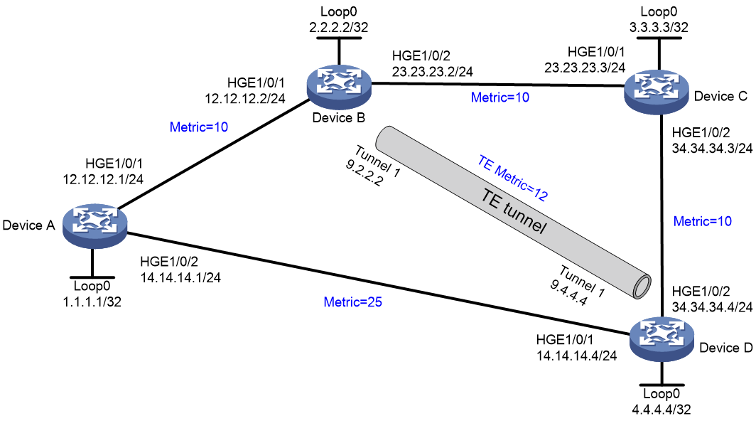
As shown in Figure 2, Device A, Device B, Device C, and Device D run OSPF.
Establish an MPLS TE tunnel from Device B to Device D that uses the path Device B—Device C—Device D, and configure MPLS TE forwarding adjacency for the tunnel.
Before the tunnel is established, traffic from Device A to Device D is forwarded through the direct link Device A—Device D. After the tunnel is established, the traffic is forwarded through the MPLS TE tunnel.
Analysis
· Enable MPLS TE on nodes and interfaces that the MPLS TE tunnels traverse.
· To make forwarding adjacency take effect, you must establish two MPLS TE tunnels in opposite directions between Device B and Device D, and enable forwarding adjacency on both devices.
· For the MPLS TE tunnel to use the path Device B—Device C—Device D, configure the path as the explicit path for the tunnel.
· For traffic from Device A to Device D to be forwarded through the MPLS TE tunnel, make sure the tunnel's metric is less than 15 (metric 25 minus 10). This example uses 12.
Software versions used
This configuration example was created and verified on Release 3606.
Restrictions and guidelines
By default, interfaces on the device are disabled (in ADM or Administratively Down state). To have an interface operate, you must use the undo shutdown command to enable that interface.
Procedures
1. Configure IP addresses for interfaces, configure basic OSPF, and set OSPF costs. (Details not shown.) For the configuration, see "Configuration files."
2. Enable MPLS TE on each node and interface that the MPLS TE tunnel traverses:
# On Device B, configure an LSR ID, and enable MPLS, MPLS TE, and RSVP-TE.
<DeviceB> system-view
[DeviceB] mpls lsr-id 2.2.2.2
[DeviceB] mpls te
[DeviceB-te] quit
[DeviceB] rsvp
[DeviceB-rsvp] quit
[DeviceB] interface hundredgige 1/0/2
[DeviceB-HundredGigE1/0/2] mpls enable
[DeviceB-HundredGigE1/0/2] mpls te enable
[DeviceB-HundredGigE1/0/2] rsvp enable
[DeviceB-HundredGigE1/0/2] quit
# On Device C, configure an LSR ID, and enable MPLS, MPLS TE, and RSVP-TE.
<DeviceC> system-view
[DeviceC] mpls lsr-id 3.3.3.3
[DeviceC] mpls te
[DeviceC-te] quit
[DeviceC] rsvp
[DeviceC-rsvp] quit
[DeviceC] interface hundredgige 1/0/1
[DeviceC-HundredGigE1/0/1] mpls enable
[DeviceC-HundredGigE1/0/1] mpls te enable
[DeviceC-HundredGigE1/0/1] rsvp enable
[DeviceC-HundredGigE1/0/1] quit
[DeviceC] interface hundredgige 1/0/2
[DeviceC-HundredGigE1/0/2] mpls enable
[DeviceC-HundredGigE1/0/2] mpls te enable
[DeviceC-HundredGigE1/0/2] rsvp enable
[DeviceC-HundredGigE1/0/2] quit
# On Device D, configure an LSR ID, and enable MPLS, MPLS TE, and RSVP-TE.
<DeviceD> system-view
[DeviceD] mpls lsr-id 4.4.4.4
[DeviceD] mpls te
[DeviceD-te] quit
[DeviceD] rsvp
[DeviceD-rsvp] quit
[DeviceD] interface hundredgige 1/0/2
[DeviceD-HundredGigE1/0/2] mpls enable
[DeviceD-HundredGigE1/0/2] mpls te enable
[DeviceD-HundredGigE1/0/2] rsvp enable
[DeviceD-HundredGigE1/0/2] quit
3. Configure OSPF TE to advertise link TE attributes:
# On Device B, enable opaque LSA advertisement and reception, and enable MPLS TE for OSPF area 0. By default, opaque LSA advertisement and reception are enabled.
[DeviceB] ospf
[DeviceB-ospf-1] opaque-capability enable
[DeviceB-ospf-1] area 0
[DeviceB-ospf-1-area-0.0.0.0] mpls te enable
[DeviceB-ospf-1-area-0.0.0.0] quit
[DeviceB-ospf-1] quit
# On Device C, enable opaque LSA advertisement and reception, and enable MPLS TE for OSPF area 0. By default, opaque LSA advertisement and reception are enabled.
[DeviceC] ospf
[DeviceC-ospf-1] opaque-capability enable
[DeviceC-ospf-1] area 0
[DeviceC-ospf-1-area-0.0.0.0] mpls te enable
[DeviceC-ospf-1-area-0.0.0.0] quit
[DeviceC-ospf-1] quit
# On Device D, enable opaque LSA advertisement and reception, and enable MPLS TE for OSPF area 0. By default, opaque LSA advertisement and reception are enabled.
[DeviceD] ospf
[DeviceD-ospf-1] opaque-capability enable
[DeviceD-ospf-1] area 0
[DeviceD-ospf-1-area-0.0.0.0] mpls te enable
[DeviceD-ospf-1-area-0.0.0.0] quit
[DeviceD-ospf-1] quit
4. Configure MPLS TE tunnels:
# On Device B, configure MPLS TE tunnel interface Tunnel 1, and specify the tunnel destination address as the LSR ID of Device D.
[DeviceB] interface tunnel 1 mode mpls-te
[DeviceB-Tunnel1] ip address 9.2.2.2 255.255.255.0
[DeviceB-Tunnel1] destination 4.4.4.4
# Configure MPLS TE to use RSVP-TE to establish the tunnel.
[DeviceB-Tunnel1] mpls te signaling rsvp-te
[DeviceB-Tunnel1] quit
# Configure an explicit path named tun1.
[DeviceB] explicit-path tun1
[DeviceB-explicit-path-tun1] nexthop 23.23.23.3
[DeviceB-explicit-path-tun1] nexthop 34.34.34.4
[DeviceB-explicit-path-tun1]quit
# Specify explicit path tun1 for the tunnel.
[DeviceB] interface tunnel 1
[DeviceB–Tunnel1] mpls te path preference 1 explicit-path tun1
# Enable forwarding adjacency for the tunnel.
[DeviceB-Tunnel1] mpls te igp advertise
# Enable OSPF on tunnel interface Tunnel 1 and set the OSPF cost to 12 for the tunnel interface.
[DeviceB-Tunnel1] ospf 1 area 0
[DeviceB-Tunnel1] ospf cost 12
[DeviceB-Tunnel1] quit
# On Device D, configure MPLS TE tunnel interface Tunnel 1, and specify the tunnel destination address as the LSR ID of Device B.
[DeviceD] interface tunnel 1 mode mpls-te
[DeviceD-Tunnel1] ip address 9.2.2.4 255.255.255.0
[DeviceD-Tunnel1] destination 2.2.2.2
# Configure MPLS TE to use RSVP-TE to establish the tunnel.
[DeviceD-Tunnel1] mpls te signaling rsvp-te
[DeviceD-Tunnel1] quit
# Configure an explicit path named tun1.
[DeviceD] explicit-path tun1
[DeviceD-explicit-path-tun1] nexthop 34.34.34.3
[DeviceD-explicit-path-tun1] nexthop 23.23.23.2
[DeviceD-explicit-path-tun1]quit
# Specify explicit path tun1 for the tunnel.
[DeviceD] interface tunnel 1
[DeviceD–Tunnel1] mpls te path preference 1 explicit-path tun1
# Enable forwarding adjacency for the tunnel.
[DeviceD-Tunnel1] mpls te igp advertise
# Enable OSPF on tunnel interface Tunnel 1 and set the OSPF cost to 12 for the tunnel interface.
[DeviceD-Tunnel1] ospf 1 area 0
[DeviceD-Tunnel1] ospf cost 12
[DeviceD-Tunnel1] quit
Verifying the configuration
# Execute the display interface tunnel brief command on Device B and Device D. This example uses Device B. The output shows that Tunnel 1 is up.
[DeviceB] display interface tunnel brief
Brief information on interfaces in route mode:
Link: ADM - administratively down; Stby - standby
Protocol: (s) - spoofing
Interface Link Protocol Primary IP Description
Tun1 UP UP 9.2.2.2
# Display routing table information on Device A. The output shows that the next hop of the route to Device D is Device B, and the cost is 22 (10 plus 12). The MPLS TE tunnel has been used during IGP route calculation.
[Device A] display ip routing-table
Destinations : 24 Routes : 24
Destination/Mask Proto Pre Cost NextHop Interface
0.0.0.0/32 Direct 0 0 127.0.0.1 InLoop0
1.1.1.1/32 Direct 0 0 127.0.0.1 InLoop0
2.2.2.2/32 OSPF 10 10 12.12.12.2 HGE1/0/1
3.3.3.3/32 OSPF 10 20 12.12.12.2 HGE1/0/1
4.4.4.4/32 OSPF 10 22 12.12.12.2 HGE1/0/1
9.2.2.0/24 OSPF 10 22 12.12.12.2 HGE1/0/1
9.4.4.0/24 OSPF 10 34 12.12.12.2 HGE1/0/1
12.12.12.0/24 Direct 0 0 12.12.12.1 HGE1/0/1
12.12.12.0/32 Direct 0 0 12.12.12.1 HGE1/0/1
12.12.12.1/32 Direct 0 0 127.0.0.1 InLoop0
12.12.12.255/32 Direct 0 0 12.12.12.1 HGE1/0/1
14.14.14.0/24 Direct 0 0 14.14.14.1 HGE1/0/2
14.14.14.0/32 Direct 0 0 14.14.14.1 HGE1/0/2
14.14.14.1/32 Direct 0 0 127.0.0.1 InLoop0
14.14.14.255/32 Direct 0 0 14.14.14.1 HGE1/0/2
23.23.23.0/24 OSPF 10 20 12.12.12.2 HGE1/0/1
34.34.34.0/24 OSPF 10 30 12.12.12.2 HGE1/0/1
127.0.0.0/8 Direct 0 0 127.0.0.1 InLoop0
127.0.0.0/32 Direct 0 0 127.0.0.1 InLoop0
127.0.0.1/32 Direct 0 0 127.0.0.1 InLoop0
127.255.255.255/32 Direct 0 0 127.0.0.1 InLoop0
255.255.255.255/32 Direct 0 0 127.0.0.1 InLoop0
Configuration files
· Device A:
#
ospf 1
area 0.0.0.0
network 1.1.1.1 0.0.0.0
network 12.12.12.0 0.0.0.255
network 14.14.14.0 0.0.0.255
#
interface LoopBack0
ip address 1.1.1.1 255.255.255.255
#
interface HundredGigE1/0/1
ip address 12.12.12.1 255.255.255.0
ospf cost 10
#
interface HundredGigE1/0/2
ip address 14.14.14.1 255.255.255.0
ospf cost 25
#
· Device B:
#
ospf 1
area 0.0.0.0
network 2.2.2.2 0.0.0.0
network 12.12.12.0 0.0.0.255
network 23.23.23.0 0.0.0.255
mpls te enable
#
mpls lsr-id 2.2.2.2
#
mpls te
#
explicit-path tun1
nexthop index 1 23.23.23.3 include strict
nexthop index 101 34.34.34.4 include strict
#
rsvp
#
interface LoopBack0
ip address 2.2.2.2 255.255.255.255
#
interface HundredGigE1/0/1
ip address 12.12.12.2 255.255.255.0
ospf cost 10
#
interface HundredGigE1/0/2
ip address 23.23.23.2 255.255.255.0
ospf cost 10
mpls enable
mpls te enable
rsvp enable
#
interface Tunnel1 mode mpls-te
ip address 9.2.2.2 255.255.255.0
ospf cost 12
ospf 1 area 0.0.0.0
mpls te path preference 1 explicit-path tun1
mpls te igp advertise
destination 4.4.4.4
#
· Device C:
#
ospf 1
area 0.0.0.0
network 3.3.3.3 0.0.0.0
network 23.23.23.0 0.0.0.255
network 34.34.34.0 0.0.0.255
mpls te enable
#
mpls lsr-id 3.3.3.3
#
mpls te
#
rsvp
#
interface LoopBack0
ip address 3.3.3.3 255.255.255.255
#
interface HundredGigE1/0/1
ip address 23.23.23.3 255.255.255.0
ospf cost 10
mpls enable
mpls te enable
rsvp enable
#
interface HundredGigE1/0/2
ip address 34.34.34.3 255.255.255.0
ospf cost 10
mpls enable
mpls te enable
rsvp enable
#
· Device D:
#
ospf 1
area 0.0.0.0
network 4.4.4.4 0.0.0.0
network 14.14.14.0 0.0.0.255
network 34.34.34.0 0.0.0.255
mpls te enable
#
mpls lsr-id 4.4.4.4
#
mpls te
#
explicit-path tun1
nexthop index 1 34.34.34.3 include strict
nexthop index 101 23.23.23.2 include strict
#
rsvp
#
interface LoopBack0
ip address 4.4.4.4 255.255.255.255
#
interface HundredGigE1/0/1
ip address 14.14.14.4 255.255.255.0
ospf cost 25
#
interface HundredGigE1/0/2
ip address 34.34.34.4 255.255.255.0
ospf cost 10
mpls enable
mpls te enable
rsvp enable
#
interface Tunnel1 mode mpls-te
ip address 9.2.2.4 255.255.255.0
ospf cost 12
ospf 1 area 0.0.0.0
mpls te path preference 1 explicit-path tun1
mpls te igp advertise
destination 2.2.2.2
#
Related documentation
· H3C S12500R Switch Router Series MPLS Command Reference-R6306
· H3C S12500R Switch Router Series MPLS Configuration Guide-R6306
