- Table of Contents
-
- H3C S12500R Ethernet Switch Router Series Config Examples-Release 36xx-6W100
- 01-Login Management Configuration Examples
- 02-RBAC Configuration Examples
- 03-Software Upgrade Examples
- 04-Ethernet Link Aggregation Configuration Examples
- 05-Port Isolation Configuration Examples
- 06-Spanning Tree Configuration Examples
- 07-VLAN Configuration Examples
- 08-VLAN Tagging Configuration Examples
- 09-DHCP Snooping Configuration Examples
- 10-Cross-Subnet Dynamic IP Address Allocation Configuration Examples
- 11-IPv6 over IPv4 Tunneling with OSPFv3 Configuration Examples
- 12-GRE Tunnel Configuration Examples
- 13-GRE with OSPF Configuration Examples
- 14-OSPF Configuration Examples
- 15-IS-IS Configuration Examples
- 16-BGP Configuration Examples
- 17-Policy-Based Routing Configuration Examples
- 18-OSPFv3 Configuration Examples
- 19-IPv6 IS-IS Configuration Examples
- 20-Routing Policy Configuration Examples
- 21-IGMP Snooping Configuration Examples
- 22-IGMP Configuration Examples
- 23-MLD Snooping Configuration Examples
- 24-Basic MPLS Configuration Examples
- 25-MPLS L3VPN Configuration Examples
- 26-ACL Configuration Examples
- 27-Control Plane-Based QoS Policy Configuration Examples
- 28-Traffic Policing Configuration Examples
- 29-GTS and Rate Limiting Configuration Examples
- 30-Priority Mapping and Queue Scheduling Configuration Examples
- 31-Traffic Filtering Configuration Examples
- 32-AAA Configuration Examples
- 33-SSH Configuration Examples
- 34-IP Source Guard Configuration Examples
- 35-Ethernet OAM Configuration Examples
- 36-CFD Configuration Examples
- 37-DLDP Configuration Examples
- 38-VRRP Configuration Examples
- 39-BFD Configuration Examples
- 40-NTP Configuration Examples
- 41-SNMP Configuration Examples
- 42-NQA Configuration Examples
- 43-Mirroring Configuration Examples
- 44-sFlow Configuration Examples
- 45-OpenFlow Configuration Examples
- 46-MAC Address Table Configuration Examples
- 47-Static Multicast MAC Address Entry Configuration Examples
- 48-IP Unnumbered Configuration Examples
- 49-Congestion Avoidance and Queue Scheduling Configuration Examples
- 50-Attack Protection Configuration Examples
- 51-Smart Link Configuration Examples
- 52-RRPP Configuration Examples
- 53-BGP Route Selection Configuration Examples
- 54-IS-IS Route Summarization Configuration Examples
- 55-MPLS OAM Configuration Examples
- 56-MPLS TE Configuration Examples
- 57-VXLAN Configuration Examples
- 58-NetStream Configuration Examples
- 59-EVPN-DCI over an MPLS L3VPN Network Configuration Examples
- 60-PTP Configuration Examples
- 61-S-MLAG Configuration Examples
- 62-MPLS SR Configuration Examples
- 63-Puppet Configuration Examples
- Related Documents
-
| Title | Size | Download |
|---|---|---|
| 54-IS-IS Route Summarization Configuration Examples | 80.22 KB |
|
H3C 12500R Switch Router Series |
|
IS-IS Route Summarization Configuration Examples |
|
|
Copyright © 2021 New H3C Technologies Co., Ltd. All rights reserved.
No part of this manual may be reproduced or transmitted in any form or by any means without prior written consent of New H3C Technologies Co., Ltd.
Except for the trademarks of New H3C Technologies Co., Ltd., any trademarks that may be mentioned in this document are the property of their respective owners.
The information in this document is subject to change without notice.
Contents
Example: Configuring IS-IS route summarization
Configuring IP addresses for interfaces
Configuring IS-IS route summarization
Introduction
This document provides IS-IS route summarization configuration examples.
Prerequisites
The configuration examples in this document were created and verified in a lab environment, and all the devices were started with the factory default configuration. When you are working on a live network, make sure you understand the potential impact of every command on your network.
This document assumes that you have basic knowledge of IS-IS route summarization.
Example: Configuring IS-IS route summarization
Network configuration
As shown in Figure 1, the five departments of a company use IS-IS to connect to the backbone network. The five departments are assigned the networks 192.168.1.0/24, 192.168.2.0/24, 192.168.3.0/24, 192.168.4.0/24, and 192.168.5.0/24. Configure IS-IS route summarization to reduce routing entries and save system resources for Device B.
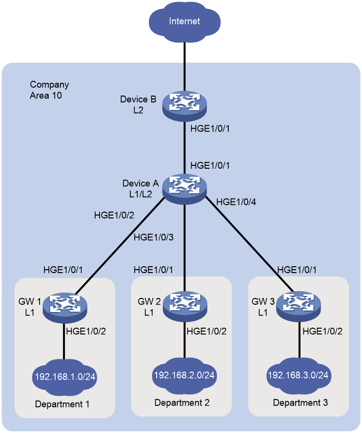
Table 1 Interface and IP address assignment
|
Device |
Interface |
IP address |
Device |
Interface |
IP address |
|
Device A |
HundredGigE1/0/1 |
172.16.1.1/24 |
Device B |
HundredGigE1/0/1 |
172.168.1.2/24 |
|
HundredGigE1/0/2 |
10.1.1.1/24 |
GW 1 |
HundredGigE1/0/1 |
10.1.1.2/24 |
|
|
|
|
|
HundredGigE1/0/2 |
192.168.1.1/24 |
|
|
HundredGigE1/0/3 |
10.1.2.1/24 |
GW 2 |
HundredGigE1/0/1 |
10.1.2.2/24 |
|
|
|
|
|
HundredGigE1/0/2 |
192.168.2.1/24 |
|
|
HundredGigE1/0/4 |
10.1.3.1/24 |
GW3 |
HundredGigE1/0/1 |
10.1.3.2/24 |
|
|
|
|
|
HundredGigE1/0/2 |
192.168.3.1/24 |
Analysis
Configure route summarization on Device A because route summarization applies only to locally generated LSPs.
To avoid blackhole routes, set the summary route to 192.168.0.0/22.
Software versions used
This configuration example was created and verified on Release 3606.
Restrictions and guidelines
By default, interfaces on the device are disabled (in ADM or Administratively Down state). To have an interface operate, you must use the undo shutdown command to enable that interface.
Procedures
Configuring IP addresses for interfaces
# Configure an IP address for the interface HundredGigE 1/0/1 on Device A.
<DeviceA> system-view
[DeviceA] interface hundredgige 1/0/1
[DeviceA-HundredGigE1/0/1] ip address 172.16.1.1 24
[DeviceA-HundredGigE1/0/1] undo shutdown
[DeviceA-HundredGigE1/0/1] quit
# Configure IP addresses for other interfaces as shown in Figure 1 in the same way HundredGigE 1/0/1 is configured. (Details not shown.)
Configuring basic IS-IS
Configuring Device A
# Enable IS-IS on Device A and configure Device A as a Level-1-2 router.
[DeviceA] isis 1
[DeviceA-isis-1] network-entity 10.0000.0000.0001.00
[DeviceA-isis-1] is-level level-1-2
[DeviceA-isis-1] quit
# Enable IS-IS on the interface HundredGigE 1/0/1.
[DeviceA] interface hundredgige 1/0/1
[DeviceA–HundredGigE1/0/1] isis enable 1
[DeviceA–HundredGigE1/0/1] quit
# Configure other interfaces in the same way HundredGigE 1/0/1 is configured. (Details not shown.)
Configuring Device B
# Enable IS-IS on Device B and configure Device B as a Level-2 router.
[DeviceB] isis 1
[DeviceB-isis-1] network-entity 10.0000.0000.0002.00
[DeviceB-isis-1] is-level level-2
[DeviceB-isis-1] quit
# Enable IS-IS on the interface HundredGigE 1/0/1.
[DeviceB] interface hundredgige 1/0/1
[DeviceB–HundredGigE1/0/1] isis enable 1
[DeviceB–HundredGigE1/0/1] quit
Configuring the gateways
# Enable IS-IS on GW 1 and configure GW 1 as a Level-1 router.
[GW1] isis 1
[GW1-isis-1] network-entity 10.0001.0001.0001.00
[GW1-isis-1] is-level level-1
[GW1-isis-1] quit
# Enable IS-IS on the interface HundredGigE 1/0/1.
[GW1] interface hundredgige 1/0/1
[GW1–HundredGigE1/0/1] isis enable 1
[GW1–HundredGigE1/0/1] quit
# Configure other gateways in the same way GW 1 is configured. (Details not shown.)
Displaying IS-IS routing information on Device B
# Display IS-IS routing information on Device B to view the network address of each department.
[DeviceB] display isis route
Route information for IS-IS(1)
------------------------------
Level-2 IPv4 Forwarding Table
-----------------------------
IPv4 Destination IntCost ExtCost ExitInterface NextHop Flags
-------------------------------------------------------------------------------
192.168.1.0/24 30 NULL HGE1/0/1 172.16.1.1 R/-/-
10.1.1.0/24 20 NULL HGE1/0/1 172.16.1.1 R/-/-
192.168.2.0/24 30 NULL HGE1/0/1 172.16.1.1 R/-/-
10.1.2.0/24 20 NULL HGE1/0/1 172.16.1.1 R/-/-
192.168.3.0/24 30 NULL HGE1/0/1 172.16.1.1 R/-/-
10.1.3.0/24 20 NULL HGE1/0/1 172.16.1.1 R/-/-
172.16.1.0/24 10 NULL HGE1/0/1 Direct D/L/-
Flags: D-Direct, R-Added to Rib, L-Advertised in LSPs, U-Up/Down Bit Set
Configuring IS-IS route summarization
# Configure IS-IS route summarization on Device A.
[DeviceA] isis 1
[DeviceA] address-family ipv4
[DeviceA-isis-1-ipv4]summary 192.168.0.0 22
Verifying the configuration
# Display IS-IS routing information on Device B.
[DeviceB] display isis route
Route information for IS-IS(1)
------------------------------
Level-2 IPv4 Forwarding Table
-----------------------------
IPv4 Destination IntCost ExtCost ExitInterface NextHop Flags
-------------------------------------------------------------------------------
10.1.1.0/24 20 NULL HGE1/0/1 172.16.1.1 R/-/-
10.1.2.0/24 20 NULL HGE1/0/1 172.16.1.1 R/-/-
10.1.3.0/24 20 NULL HGE1/0/1 172.16.1.1 R/-/-
172.16.1.0/24 10 NULL HGE1/0/1 Direct D/L/-
192.168.0.0/22 30 NULL HGE1/0/1 172.16.1.1 R/-/-
Flags: D-Direct, R-Added to Rib, L-Advertised in LSPs, U-Up/Down Bit Set
The output shows that the networks have been summarized into a single network 192.168.0.0/22.
Configuration files
· Device A:
#
isis 1
network-entity 10.0000.0000.0001.00
#
address-family ipv4 unicast
summary 192.168.0.0 255.255.252.0
#
interface HundredGigE1/0/1
ip address 172.16.1.1 255.255.255.0
isis enable 1
#
interface HundredGigE1/0/2
ip address 10.1.1.1 255.255.255.0
isis enable 1
#
interface HundredGigE1/0/3
ip address 10.1.2.1 255.255.255.0
isis enable 1
#
interface HundredGigE1/0/4
ip address 10.1.3.1 255.255.255.0
isis enable 1
#
· Device B:
#
isis 1
is-level level-2
network-entity 10.0000.0000.0002.00
#
interface HundredGigE1/0/1
ip address 172.16.1.2 255.255.255.0
isis enable 1
#
· GW 1:
#
isis 1
is-level level-1
network-entity 10.0001.0001.0001.00
#
interface HundredGigE1/0/1
ip address 10.1.1.2 255.255.255.0
isis enable 1
#
interface HundredGigE1/0/2
ip address 192.168.1.1 255.255.255.0
isis enable 1
#
· The configuration files for other gateways are similar to the configuration file for GW 1. (Details not shown.)
Related documentation
· H3C S12500R Switch Router Series Layer 3—IP Routing Command Reference-R3606
· H3C S12500R Switch Router Series Layer 3—IP Routing Configuration Guide-R3606
