- Table of Contents
-
- H3C S12500R Ethernet Switch Router Series Config Examples-Release 36xx-6W100
- 01-Login Management Configuration Examples
- 02-RBAC Configuration Examples
- 03-Software Upgrade Examples
- 04-Ethernet Link Aggregation Configuration Examples
- 05-Port Isolation Configuration Examples
- 06-Spanning Tree Configuration Examples
- 07-VLAN Configuration Examples
- 08-VLAN Tagging Configuration Examples
- 09-DHCP Snooping Configuration Examples
- 10-Cross-Subnet Dynamic IP Address Allocation Configuration Examples
- 11-IPv6 over IPv4 Tunneling with OSPFv3 Configuration Examples
- 12-GRE Tunnel Configuration Examples
- 13-GRE with OSPF Configuration Examples
- 14-OSPF Configuration Examples
- 15-IS-IS Configuration Examples
- 16-BGP Configuration Examples
- 17-Policy-Based Routing Configuration Examples
- 18-OSPFv3 Configuration Examples
- 19-IPv6 IS-IS Configuration Examples
- 20-Routing Policy Configuration Examples
- 21-IGMP Snooping Configuration Examples
- 22-IGMP Configuration Examples
- 23-MLD Snooping Configuration Examples
- 24-Basic MPLS Configuration Examples
- 25-MPLS L3VPN Configuration Examples
- 26-ACL Configuration Examples
- 27-Control Plane-Based QoS Policy Configuration Examples
- 28-Traffic Policing Configuration Examples
- 29-GTS and Rate Limiting Configuration Examples
- 30-Priority Mapping and Queue Scheduling Configuration Examples
- 31-Traffic Filtering Configuration Examples
- 32-AAA Configuration Examples
- 33-SSH Configuration Examples
- 34-IP Source Guard Configuration Examples
- 35-Ethernet OAM Configuration Examples
- 36-CFD Configuration Examples
- 37-DLDP Configuration Examples
- 38-VRRP Configuration Examples
- 39-BFD Configuration Examples
- 40-NTP Configuration Examples
- 41-SNMP Configuration Examples
- 42-NQA Configuration Examples
- 43-Mirroring Configuration Examples
- 44-sFlow Configuration Examples
- 45-OpenFlow Configuration Examples
- 46-MAC Address Table Configuration Examples
- 47-Static Multicast MAC Address Entry Configuration Examples
- 48-IP Unnumbered Configuration Examples
- 49-Congestion Avoidance and Queue Scheduling Configuration Examples
- 50-Attack Protection Configuration Examples
- 51-Smart Link Configuration Examples
- 52-RRPP Configuration Examples
- 53-BGP Route Selection Configuration Examples
- 54-IS-IS Route Summarization Configuration Examples
- 55-MPLS OAM Configuration Examples
- 56-MPLS TE Configuration Examples
- 57-VXLAN Configuration Examples
- 58-NetStream Configuration Examples
- 59-EVPN-DCI over an MPLS L3VPN Network Configuration Examples
- 60-PTP Configuration Examples
- 61-S-MLAG Configuration Examples
- 62-MPLS SR Configuration Examples
- 63-Puppet Configuration Examples
- Related Documents
-
| Title | Size | Download |
|---|---|---|
| 25-MPLS L3VPN Configuration Examples | 264.22 KB |
|
|
|
H3C S12500R Switch Router Series |
|
MPLS L3VPN Configuration Examples |
|
|
Copyright © 2021 New H3C Technologies Co., Ltd. All rights reserved.
No part of this manual may be reproduced or transmitted in any form or by any means without prior written consent of New H3C Technologies Co., Ltd.
Except for the trademarks of New H3C Technologies Co., Ltd., any trademarks that may be mentioned in this document are the property of their respective owners.
The information in this document is subject to change without notice.
Introduction
This document provides MPLS L3VPN configuration examples.
Prerequisites
The configuration examples in this document were created and verified in a lab environment, and all the devices were started with the factory default configuration. When you are working on a live network, make sure you understand the potential impact of every command on your network.
This document assumes that you have basic knowledge of MPLS L3VPN.
Example: Configuring MPLS L3VPN
Network configuration
As shown in Figure 1, configure MPLS L3VPN to allow communication between different sites of a customer and to isolate different customers.
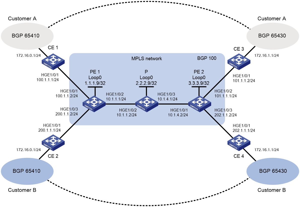
Analysis
To generate inner labels, and deliver VPN routing information to the remote PE, configure MP-BGP peers between PEs.
To generate outer labels to tunnel the VPN packets over the MPLS backbone, configure a routing protocol and MPLS LDP on the MPLS backbone.
To identify routing information for different customers on PEs, perform the following tasks on each PE:
· Create a VPN instance for each customer.
· Configure an RD and route targets for each VPN instance.
· Redistribute internal routes of each site to the corresponding VPN instance.
Software versions used
This configuration example was created and verified on Release 3606.
Restrictions and guidelines
Associating an interface with a VPN instance deletes the IP address of the interface. You must reconfigure the interface's IP address after the association.
Procedures
1. Configure OSPF on the MPLS backbone to ensure IP connectivity within the backbone:
# On PE 1, configure IP addresses for the loopback interface and the core-facing interface.
<PE1> system-view
[PE1] interface loopback 0
[PE1-LoopBack0] ip address 1.1.1.9 32
[PE1-LoopBack0] quit
[PE1] interface hundredgige 1/0/2
[PE1-HundredGigE1/0/2] ip address 10.1.1.1 24
[PE1-HundredGigE1/0/2] quit
# On PE 1, configure OSPF to advertise backbone networks.
[PE1] ospf
[PE1-ospf-1] area 0
[PE1-ospf-1-area-0.0.0.0] network 10.1.1.0 0.0.0.255
[PE1-ospf-1-area-0.0.0.0] network 1.1.1.9 0.0.0.0
[PE1-ospf-1-area-0.0.0.0] quit
[PE1-ospf-1] quit
# On P, configure IP addresses for interfaces, including the loopback interface.
<P> system-view
[P] interface loopback 0
[P-LoopBack0] ip address 2.2.2.9 32
[P-LoopBack0] quit
[P] interface hundredgige 1/0/2
[P-HundredGigE1/0/2] ip address 10.1.1.2 24
[P-HundredGigE1/0/2] quit
[P] interface hundredgige 1/0/3
[P-HundredGigE1/0/3] ip address 10.1.4.1 24
[P-HundredGigE1/0/3] quit
# On P, configure OSPF to advertise backbone networks.
[P] ospf
[P-ospf-1] area 0
[P-ospf-1-area-0.0.0.0] network 10.1.1.0 0.0.0.255
[P-ospf-1-area-0.0.0.0] network 10.1.4.0 0.0.0.255
[P-ospf-1-area-0.0.0.0] network 2.2.2.9 0.0.0.0
[P-ospf-1-area-0.0.0.0] quit
[P-ospf-1] quit
# On PE 2, configure IP addresses for the loopback interface and the core-facing interface.
<PE2> system-view
[PE2] interface loopback 0
[PE2-LoopBack0] ip address 3.3.3.9 32
[PE2-LoopBack0] quit
[PE2] interface hundredgige 1/0/1
[PE2-HundredGigE1/0/1] ip address 10.1.4.2 24
[PE2-HundredGigE1/0/1] quit
# On PE 2, configure OSPF to advertise backbone networks.
[PE2] ospf
[PE2-ospf-1] area 0
[PE2-ospf-1-area-0.0.0.0] network 10.1.4.0 0.0.0.255
[PE2-ospf-1-area-0.0.0.0] network 3.3.3.9 0.0.0.0
[PE2-ospf-1-area-0.0.0.0] quit
[PE2-ospf-1] quit
# Verify that OSPF neighbor relationships in Full state have been established on the backbone devices.
[PE1] display ospf peer verbose
OSPF Process 1 with Router ID 1.1.1.9
Neighbors
Area 0.0.0.0 interface 10.1.1.1(HundredGigE1/0/2)'s neighbors
Router ID: 2.2.2.9 Address: 10.1.1.2 GR State: Normal
State: Full Mode: Nbr is Master Priority: 1
DR: 10.1.1.2 BDR: 10.1.1.1 MTU: 0
Options is 0x02 (-|-|-|-|-|-|E|-)
Dead timer due in 38 sec
Neighbor is up for 17:30:25
Authentication Sequence: [ 0 ]
Neighbor state change count: 6
BFD status: Disabled
# Verify that the PEs have learned the routes to the loopback interfaces of each other.
[PE1] display ip routing-table protocol ospf
Summary Count : 5
OSPF Routing table Status : <Active>
Summary Count : 3
Destination/Mask Proto Pre Cost NextHop Interface
2.2.2.9/32 OSPF 10 1 10.1.1.2 HGE1/0/2
3.3.3.9/32 OSPF 10 2 10.1.1.2 HGE1/0/2
10.1.4.0/24 OSPF 10 2 10.1.1.2 HGE1/0/2
OSPF Routing table Status : <Inactive>
Summary Count : 2
Destination/Mask Proto Pre Cost NextHop Interface
1.1.1.9/32 OSPF 10 0 1.1.1.9 Loop0
10.1.1.0/24 OSPF 10 1 10.1.1.1 HGE1/0/2
2. Configure basic MPLS and MPLS LDP on the MPLS backbone to establish LDP LSPs:
# Configure PE 1.
[PE1] mpls lsr-id 1.1.1.9
[PE1] mpls ldp
[PE1-ldp] quit
[PE1] interface hundredgige 1/0/2
[PE1-HundredGigE1/0/2] mpls enable
[PE1-HundredGigE1/0/2] mpls ldp enable
[PE1-HundredGigE1/0/2] quit
# Configure P.
[P] mpls lsr-id 2.2.2.9
[P] mpls ldp
[P-ldp] quit
[P] interface hundredgige 1/0/2
[P-HundredGigE1/0/2] mpls enable
[P-HundredGigE1/0/2] mpls ldp enable
[P-HundredGigE1/0/2] quit
[P] interface hundredgige 1/0/3
[P-HundredGigE1/0/3] mpls enable
[P-HundredGigE1/0/3] mpls ldp enable
[P-HundredGigE1/0/3] quit
# Configure PE 2.
[PE2] mpls lsr-id 3.3.3.9
[PE2] mpls ldp
[PE2-ldp] quit
[PE2] interface hundredgige 1/0/1
[PE2-HundredGigE1/0/1] mpls enable
[PE2-HundredGigE1/0/1] mpls ldp enable
[PE2-HundredGigE1/0/1] quit
# Verify that LDP sessions in Operational state have been established.
[PE1] display mpls ldp peer
Total number of peers: 1
Peer LDP ID State Role GR MD5 KA Sent/Rcvd
2.2.2.9:0 Operational Passive Off Off 5/5
# Verify that the LSPs have been established by LDP.
[PE1] display mpls ldp lsp
Status Flags: * - stale, L - liberal, B - backup
FECs: 4 Ingress: 1 Transit: 1 Egress: 3
FEC In/Out Label Nexthop OutInterface/LSINDEX
1.1.1.9/32 3/-
-/1151(L)
2.2.2.9/32 -/3 10.1.1.2 HGE1/0/2
1151/3 10.1.1.2 HGE1/0/2
3.3.3.9/32 -/1150 10.1.1.2 HGE1/0/2
1150/1150 10.1.1.2 HGE1/0/2
3. Configure VPN instances on PEs to allow CE access:
# On PE 1, create VPN instance customerA for Customer A.
[PE1] ip vpn-instance customerA
# On PE 1, configure the RD as 100:1 for the VPN instance.
[PE1-vpn-instance-customerA] route-distinguisher 100:1
# On PE 1, specify the import target as 111:1 and the export target as 222:1 for the VPN instance. You can configure the same value for both the import and export targets to simplify management.
[PE1-vpn-instance-customerA] vpn-target 111:1 import-extcommunity
[PE1-vpn-instance-customerA] vpn-target 222:1 export-extcommunity
[PE1-vpn-instance-customerA] quit
# On PE 1, create VPN instance customerB for Customer B.
[PE1] ip vpn-instance customerB
# On PE 1, configure the RD as 200:1 for the VPN instance.
[PE1-vpn-instance-customerB] route-distinguisher 200:1
# On PE 1, specify the import target and export target for the VPN instance as 333:1 and 444:1.
[PE1-vpn-instance-customerB] vpn-target 333:1 import-extcommunity
[PE1-vpn-instance-customerB] vpn-target 444:1 export-extcommunity
[PE1-vpn-instance-customerB] quit
# On PE 1, associate HundredGigE1/0/1 with VPN instance customerA.
[PE1] interface hundredgige 1/0/1
[PE1-HundredGigE1/0/1] ip binding vpn-instance customerA
[PE1-HundredGigE1/0/1] ip address 100.1.1.2 24
[PE1-HundredGigE1/0/1] quit
# On PE 1, associate HundredGigE1/0/3 with VPN instance customerB.
[PE1] interface hundredgige 1/0/3
[PE1-HundredGigE1/0/3] ip binding vpn-instance customerB
[PE1-HundredGigE1/0/3] ip address 200.1.1.2 24
[PE1-HundredGigE1/0/3] quit
# On PE 2, create VPN instance customerA for Customer A.
[PE2] ip vpn-instance customerA
# On PE 2, configure an RD for the VPN instance. HP recommends configuring the same RD as the one configured for VPN instance customerA on PE 1.
[PE2-vpn-instance-customerA] route-distinguisher 100:1
# On PE 2, specify the import target and export target the same as the export target and import target on PE 1.
[PE2-vpn-instance-customerA] vpn-target 222:1 import-extcommunity
[PE2-vpn-instance-customerA] vpn-target 111:1 export-extcommunity
[PE2-vpn-instance-customerA] quit
# On PE 2, create VPN instance customerB for Customer B.
[PE2] ip vpn-instance customerB
# On PE 2, configure the RD as 200:1 for the VPN instance.
[PE2-vpn-instance-customerB] route-distinguisher 200:1
# On PE 2, specify the import target and export target the same as the export target and import target on PE 1.
[PE2-vpn-instance-customerB] vpn-target 444:1 import-extcommunity
[PE2-vpn-instance-customerB] vpn-target 333:1 export-extcommunity
[PE2-vpn-instance-customerB] quit
# On PE 2, associate HundredGigE1/0/2 with VPN instance customerA.
[PE2] interface hundredgige 1/0/2
[PE2-HundredGigE1/0/2] ip binding vpn-instance customerA
[PE2-HundredGigE1/0/2] ip address 101.1.1.1 24
[PE2-HundredGigE1/0/2] quit
# On PE 2, associate HundredGigE1/0/3 with VPN instance customerB.
[PE2] interface hundredgige 1/0/3
[PE2-HundredGigE1/0/3] ip binding vpn-instance customerB
[PE2-HundredGigE1/0/3] ip address 202.1.1.2 24
[PE2-HundredGigE1/0/3] quit
# Configure IP addresses for interfaces on the CEs, as shown in Figure 1. (Details not shown.)
# Execute the display ip vpn-instance command on the PEs to display VPN instance configurations.
[PE1] display ip vpn-instance
Total VPN-Instances configured : 2
Total IPv4 VPN-Instances configured : 1
Total IPv6 VPN-Instances configured : 1
Total IPv4 VPN-Instances EVPN configured : 0
Total IPv6 VPN-Instances EVPN configured : 0
VPN-Instance Name RD Address family Create time
customerA 100:1 IPv4/IPv6/EVPN 2020/03/22 13:20:08
customerB 200:1 IPv4/IPv6/EVPN 2020/03/22 13:20:20
# Use the ping command on the PEs to verify that the PEs can ping their attached CEs.
[PE1] ping -vpn-instance customerA 100.1.1.1
Ping 100.1.1.1 (100.1.1.1): 56 data bytes, press CTRL_C to break
56 bytes from 100.1.1.1: icmp_seq=0 ttl=255 time=1.000 ms
56 bytes from 100.1.1.1: icmp_seq=1 ttl=255 time=2.000 ms
56 bytes from 100.1.1.1: icmp_seq=2 ttl=255 time=0.000 ms
56 bytes from 100.1.1.1: icmp_seq=3 ttl=255 time=1.000 ms
56 bytes from 100.1.1.1: icmp_seq=4 ttl=255 time=0.000 ms
--- Ping statistics for 100.1.1.1 in VPN instance customerA ---
5 packet(s) transmitted, 5 packet(s) received, 0.0% packet loss
round-trip min/avg/max/std-dev = 0.000/0.800/2.000/0.748 ms
4. Establish EBGP peer relationships between PEs and CEs, and redistribute VPN routes into BGP:
# On PE 1, create BGP process 100.
[PE1] bgp 100
# On PE 1, specify CE 1 as a peer and redistribute direct routes of CE 1 into the BGP routing table of VPN instance customerA.
[PE1-bgp-default] ip vpn-instance customerA
[PE1-bgp-default-customerA] peer 100.1.1.1 as-number 65410
[PE1-bgp-default-customerA] address-family ipv4 unicast
[PE1-bgp-default-ipv4-customerA] peer 100.1.1.1 enable
[PE1-bgp-default-ipv4-customerA] import-route direct
[PE1-bgp-default-ipv4-customerA] quit
[PE1-bgp-default-customerA] quit
# On PE 1, specify CE 2 as a peer and redistribute direct routes of CE 2 into the BGP routing table of VPN instance customerB.
[PE1-bgp-default] ip vpn-instance customerB
[PE1-bgp-default-customerB] peer 200.1.1.1 as-number 65410
[PE1-bgp-default-customerB] address-family ipv4 unicast
[PE1-bgp-default-ipv4-customerB] peer 200.1.1.1 enable
[PE1-bgp-default-ipv4-customerB] import-route direct
[PE1-bgp-default-ipv4-customerB] quit
[PE1-bgp-default-customerB] quit
[PE1-bgp-default] quit
# On PE 2, create BGP process 100.
[PE2] bgp 100
# On PE 2, specify CE 3 as a peer and redistribute direct routes of CE 3 into the BGP routing table of VPN instance customerA.
[PE2-bgp-default] ip vpn-instance customerA
[PE2-bgp-default-customerA] peer 101.1.1.2 as-number 65430
[PE2-bgp-default-customerA] address-family ipv4 unicast
[PE2-bgp-default-ipv4-customerA] peer 101.1.1.2 enable
[PE2-bgp-default-ipv4-customerA] import-route direct
[PE2-bgp-default-ipv4-customerA] quit
[PE2-bgp-default-customerA] quit
# On PE 2, specify CE 4 as a peer and redistribute direct routes of CE 4 into the BGP routing table of VPN instance customerB.
[PE2-bgp-default] ip vpn-instance customerB
[PE2-bgp-default-customerB] peer 202.1.1.1 as-number 65430
[PE2-bgp-default-customerB] address-family ipv4 unicast
[PE2-bgp-default-ipv4-customerB] peer 202.1.1.1 enable
[PE2-bgp-default-ipv4-customerB] import-route direct
[PE2-bgp-default-ipv4-customerB] quit
[PE2-bgp-default-customerB] quit
[PE2-bgp-default] quit
# On CE 1, create BGP process 65410, specify 100.1.1.2 as the peer, and specify the peer's AS number as 100.
<CE1> system-view
[CE1] bgp 65410
[CE1-bgp-default] peer 100.1.1.2 as-number 100
# On CE 1, enable BGP to exchange IPv4 unicast routing information with peer 100.1.1.2.
[CE1-bgp-default] address-family ipv4 unicast
[CE1-bgp-default-ipv4] peer 100.1.1.2 enable
# On CE 1, redistribute the direct route for the site into EBGP.
[CE1-bgp-default-ipv4] import-route direct
[CE1-bgp-default-ipv4] quit
[CE1-bgp-default] quit
# On CE 2, create BGP process 65410, specify 200.1.1.2 as the peer, and specify the peer's AS number as 100.
<CE2> system-view
[CE2] bgp 65410
[CE2-bgp-default] peer 200.1.1.2 as-number 100
# On CE 2, enable BGP to exchange IPv4 unicast routing information with peer 200.1.1.2.
[CE2-bgp-default] address-family ipv4 unicast
[CE2-bgp-default-ipv4] peer 200.1.1.2 enable
# On CE 2, redistribute the direct route for the site into EBGP.
[CE2-bgp-default-ipv4] import-route direct
[CE2-bgp-default-ipv4] quit
[CE2-bgp-default] quit
# On CE 3, create BGP process 65430, specify 101.1.1.1 as the peer, and specify the peer's AS number as 100.
<CE3> system-view
[CE3] bgp 65430
[CE3-bgp-default] peer 101.1.1.1 as-number 100
# On CE 3, enable BGP to exchange IPv4 unicast routing information with peer 101.1.1.1.
[CE3-bgp-default] address-family ipv4 unicast
[CE3-bgp-default-ipv4] peer 101.1.1.1 enable
# On CE 3, redistribute the direct route for the site into EBGP.
[CE3-bgp-default-ipv4] import-route direct
[CE3-bgp-default-ipv4] quit
[CE3-bgp-default] quit
# On CE 4, create BGP process 65430, specify 202.1.1.2 as the peer, and specify the peer's AS number as 100.
<CE4> system-view
[CE4] bgp 65430
[CE4-bgp-default] peer 202.1.1.2 as-number 100
# On CE 4, enable BGP to exchange IPv4 unicast routing information with peer 202.1.1.2.
[CE4-bgp-default] address-family ipv4 unicast
[CE4-bgp-default-ipv4] peer 202.1.1.2 enable
# On CE 4, redistribute the direct route for the site into EBGP.
[CE4-bgp-default-ipv4] import-route direct
[CE4-bgp-default-ipv4] quit
[CE4-bgp-default] quit
# Verify that a BGP peer relationship in Established state has been established between a PE and a CE.
[PE1] display bgp peer ipv4 vpn-instance customerA
BGP local router ID: 1.1.1.9
Local AS number: 100
Total number of peers: 1 Peers in established state: 1
* - Dynamically created peer
Peer AS MsgRcvd MsgSent OutQ PrefRcv Up/Down State
100.1.1.1 65410 4 4 0 2 13:35:25 Established
5. Create an MP-IBGP peer relationship between PEs:
# On PE 1, configure 3.3.3.9 as the BGP peer and specify Loopback 0 as the source interface for sending routing updates to the peer.
[PE1] bgp 100
[PE1-bgp-default] peer 3.3.3.9 as-number 100
[PE1-bgp-default] peer 3.3.3.9 connect-interface loopback 0
# On PE 1, enable the peer 3.3.3.9 for the BGP-VPNv4 address family.
[PE1-bgp-default] address-family vpnv4
[PE1-bgp-default-vpnv4] peer 3.3.3.9 enable
[PE1-bgp-default-vpnv4] quit
[PE1-bgp-default] quit
# On PE 2, configure 1.1.1.9 as the BGP peer and specify Loopback 0 as the source interface for sending routing updates to the peer.
[PE2] bgp 100
[PE2-bgp-default] peer 1.1.1.9 as-number 100
[PE2-bgp-default] peer 1.1.1.9 connect-interface loopback 0
# On PE 2, enable the peer 1.1.1.9 for the BGP-VPNv4 address family.
[PE2-bgp-default] address-family vpnv4
[PE2-bgp-default-vpnv4] peer 1.1.1.9 enable
[PE2-bgp-default-vpnv4] quit
[PE2-bgp-default] quit
# Verify that a BGP peer relationship in Established state has been established between the PEs.
[PE1] display bgp peer vpnv4
BGP local router ID: 1.1.1.9
Local AS number: 100
Total number of peers: 1 Peers in established state: 1
* - Dynamically created peer
Peer AS MsgRcvd MsgSent OutQ PrefRcv Up/Down State
3.3.3.9 100 8 8 0 0 00:00:08 Established
Verifying the configuration
# Execute the display ip routing-table vpn-instance command on the PEs.
[PE1] display ip routing-table vpn-instance customerA
Destinations : 13 Routes : 13
Destination/Mask Proto Pre Cost NextHop Interface
0.0.0.0/32 Direct 0 0 127.0.0.1 InLoop0
100.1.1.0/24 Direct 0 0 100.1.1.2 HGE1/0/1
100.1.1.0/32 Direct 0 0 100.1.1.2 HGE1/0/1
100.1.1.2/32 Direct 0 0 127.0.0.1 InLoop0
100.1.1.255/32 Direct 0 0 100.1.1.2 HGE1/0/1
101.1.1.0/24 BGP 255 0 3.3.3.9 HGE1/0/2
127.0.0.0/8 Direct 0 0 127.0.0.1 InLoop0
127.0.0.0/32 Direct 0 0 127.0.0.1 InLoop0
127.0.0.1/32 Direct 0 0 127.0.0.1 InLoop0
127.255.255.255/32 Direct 0 0 127.0.0.1 InLoop0
224.0.0.0/4 Direct 0 0 0.0.0.0 NULL0
224.0.0.0/24 Direct 0 0 0.0.0.0 NULL0
255.255.255.255/32 Direct 0 0 127.0.0.1 InLoop0
The output shows that PE 1 has a route to the remote CE of Customer A. Output on PE 2 is similar.
# Verify that CEs of the same VPN can ping each other, whereas those of different VPNs cannot. For example, CE 1 can ping CE 3 (101.1.1.2), but it cannot ping CE 4 (202.1.1.1). (Details not shown.)
Configuration files
· PE 1:
#
ip vpn-instance customerA
route-distinguisher 100:1
vpn-target 111:1 import-extcommunity
vpn-target 222:1 export-extcommunity
#
ip vpn-instance customerB
route-distinguisher 200:1
vpn-target 333:1 import-extcommunity
vpn-target 444:1 export-extcommunity
#
ospf 1
area 0.0.0.0
network 1.1.1.9 0.0.0.0
network 10.1.1.0 0.0.0.255
#
mpls lsr-id 1.1.1.9
#
mpls ldp
#
interface LoopBack0
ip address 1.1.1.9 255.255.255.255
#
interface HundredGigE1/0/1
port link-mode route
ip binding vpn-instance customerA
ip address 100.1.1.2 255.255.255.0
#
interface HundredGigE1/0/2
port link-mode route
ip address 10.1.1.1 255.255.255.0
mpls enable
mpls ldp enable
#
interface HundredGigE1/0/3
port link-mode route
ip binding vpn-instance customerB
ip address 200.1.1.2 255.255.255.0
#
bgp 100
peer 3.3.3.9 as-number 100
peer 3.3.3.9 connect-interface LoopBack0
#
address-family vpnv4
peer 3.3.3.9 enable
#
ip vpn-instance customerA
peer 100.1.1.1 as-number 65410
#
address-family ipv4 unicast
import-route direct
peer 100.1.1.1 enable
#
ip vpn-instance customerB
peer 200.1.1.1 as-number 65410
#
address-family ipv4 unicast
import-route direct
peer 200.1.1.1 enable
#
· P:
#
ospf 1
area 0.0.0.0
network 2.2.2.9 0.0.0.0
network 10.1.1.0 0.0.0.255
network 10.1.4.0 0.0.0.255
#
mpls lsr-id 2.2.2.9
#
mpls ldp
#
interface LoopBack0
ip address 2.2.2.9 255.255.255.255
#
interface HundredGigE1/0/2
port link-mode route
ip address 10.1.1.2 255.255.255.0
mpls enable
mpls ldp enable
#
interface HundredGigE1/0/3
port link-mode route
ip address 10.1.4.1 255.255.255.0
mpls enable
mpls ldp enable
#
· PE 2:
#
ip vpn-instance customerA
route-distinguisher 100:1
vpn-target 111:1 export-extcommunity
vpn-target 222:1 import-extcommunity
#
ip vpn-instance customerB
route-distinguisher 200:1
vpn-target 333:1 export-extcommunity
vpn-target 444:1 import-extcommunity
#
ospf 1
area 0.0.0.0
network 10.1.4.0 0.0.0.255
network 3.3.3.9 0.0.0.0
#
mpls lsr-id 3.3.3.9
#
mpls ldp
#
interface LoopBack0
ip address 3.3.3.9 255.255.255.255
#
interface HundredGigE1/0/1
port link-mode route
ip address 10.1.4.2 255.255.255.0
mpls enable
mpls ldp enable
#
interface HundredGigE1/0/2
port link-mode route
ip binding vpn-instance customerA
ip address 101.1.1.1 255.255.255.0
#
interface HundredGigE1/0/3
port link-mode route
ip binding vpn-instance customerB
ip address 202.1.1.2 255.255.255.0
#
bgp 100
peer 1.1.1.9 as-number 100
peer 1.1.1.9 connect-interface LoopBack0
#
address-family vpnv4
peer 1.1.1.9 enable
#
ip vpn-instance customerA
peer 101.1.1.2 as-number 65430
#
address-family ipv4 unicast
import-route direct
peer 101.1.1.2 enable
#
ip vpn-instance customerB
peer 202.1.1.1 as-number 65430
#
address-family ipv4 unicast
import-route direct
peer 202.1.1.1 enable
#
· CE 1:
#
interface HundredGigE1/0/1
port link-mode route
ip address 100.1.1.1 255.255.255.0
#
bgp 65410
peer 100.1.1.2 as-number 100
#
address-family ipv4 unicast
import-route direct
peer 100.1.1.2 enable
#
· CE 2:
#
interface HundredGigE1/0/1
port link-mode route
ip address 200.1.1.1 255.255.255.0
#
bgp 65410
peer 200.1.1.2 as-number 100
#
address-family ipv4 unicast
import-route direct
peer 200.1.1.2 enable
#
· CE 3:
#
interface HundredGigE1/0/1
port link-mode route
ip address 101.1.1.2 255.255.255.0
#
bgp 65430
peer 101.1.1.1 as-number 100
#
address-family ipv4 unicast
import-route direct
peer 101.1.1.1 enable
#
· CE 4:
#
interface HundredGigE1/0/1
port link-mode route
ip address 202.1.1.1 255.255.255.0
#
bgp 65430
peer 202.1.1.2 as-number 100
#
address-family ipv4 unicast
import-route direct
peer 202.1.1.2 enable
#
Example: Configuring HoVPN
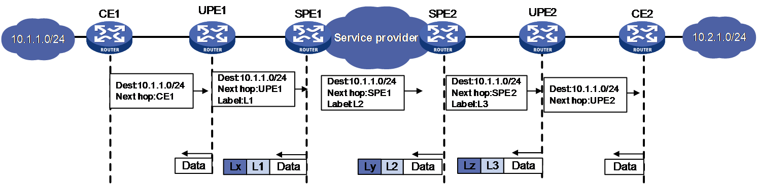
Hierarchy of VPN (HoVPN) divides PEs into underlayer PEs (UPEs) or user-end PEs, and superstratum PEs (SPEs) or service provider-end PEs. UPEs and SPEs form a hierarchical PE structure.
UPEs and SPEs together provide the functions of a conventional PE.
· UPE—Provides user access. It maintains the routes of directly connected VPN sites. It does not maintain the routes of the remote sites in the VPN, or it only maintains their summary routes. A UPE assigns inner labels to the routes of its directly connected sites, and advertises the labels along with VPN routes to the SPE through MP-BGP.
· SPE—Manages and advertises VPN routes. It maintains all the routes of the VPNs connected through UPEs, including the routes of both the local and remote sites. An SPE advertises routes along with labels to UPEs, including the default routes of VPN instances or summary routes and the routes permitted by the routing policy. By using routing policies, you can control which sites in a VPN can communicate with each other.
Figure 2 Routing process and label exchange for HoVPN
Network configuration
As shown in Figure 3, the SPEs are in AS 100 and the UPEs are in AS 200. SPE 1 and SPE 2 are in the backbone network of the service provider, and UPE 1 and UPE 2 are connected to CE 1 and CE 2 in VPN 1, respectively. Configure HoVPN and routing policies to meet the following requirements:
· Allow communication between interface HundredGigE 1/0/1 on CE 1 and interface HundredGigE 1/0/1 on CE 2.
· Block communication between HundredGigE 1/0/3 on CE 1 and HundredGigE 1/0/1 on CE 2.
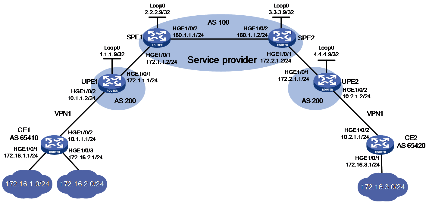
Analysis
To ensure that VLAN 10 can communicate with VLAN 30 but VLAN 20 cannot, configure a routing policy on SPE 2 to advertise only the route of subnet 172.16.1.0/24 to UPE 2.
Software versions used
This configuration example was created and verified on Release 3606.
Restrictions and guidelines
When you configure HoVPN, follow these restrictions and guidelines:
· For an SPE to advertise routes to its connected UPE, perform the following configurations on the SPE:
¡ Configure a routing policy to specify the routes that can be advertised.
¡ Configure the BGP to advertise the routes permitted by the routing policy to the UPE.
· For an SPE and a UPE (EBGP peers) to advertise labels to each other, perform the following configurations:
¡ Enable BGP to exchange labeled routes with the peer.
¡ Configure a routing policy to specify the routes that can be advertised, and assign MPLS labels to the matching routes.
¡ Apply the routing policy to routes outgoing to the peer.
· Associating an interface with a VPN instance deletes the IP address of the interface. You must reconfigure the IP address of the interface after the association. To avoid configuring the interface's IP address twice, configure the association first.
Procedures
1. Enable MPLS and MPLS LDP on SPEs, and configure the IGP protocol (OSPF, in this example):
# On SPE 1, configure basic MPLS and MPLS LDP to establish LDP LSPs.
<SPE1> system-view
[SPE1] interface loopback 0
[SPE1-LoopBack0] ip address 2.2.2.9 32
[SPE1-LoopBack0] quit
[SPE1] mpls lsr-id 2.2.2.9
[SPE1] mpls ldp
[SPE1-ldp] quit
[SPE1] interface hundredgige 1/0/1
[SPE1-HundredGigE1/0/1] ip address 172.1.1.2 24
[SPE1-HundredGigE1/0/1] mpls enable
[SPE1-HundredGigE1/0/1] quit
[SPE1] interface hundredgige 1/0/2
[SPE1-HundredGigE1/0/2] ip address 180.1.1.1 24
[SPE1-HundredGigE1/0/2] mpls enable
[SPE1-HundredGigE1/0/2] mpls ldp enable
[SPE1-HundredGigE1/0/2] quit
# On SPE 1, configure OSPF.
[SPE1] ospf
[SPE1-ospf-1] area 0
[SPE1-ospf-1-area-0.0.0.0] network 2.2.2.9 0.0.0.0
[SPE1-ospf-1-area-0.0.0.0] network 180.1.1.0 0.0.0.255
[SPE1-ospf-1-area-0.0.0.0] quit
[SPE1-ospf-1] quit
# On SPE 2, configure basic MPLS and MPLS LDP to establish LDP LSPs.
<SPE2> system-view
[SPE2] interface loopback 0
[SPE2-LoopBack0] ip address 3.3.3.9 32
[SPE2-LoopBack0] quit
[SPE2] mpls lsr-id 3.3.3.9
[SPE2] mpls ldp
[SPE2-ldp] quit
[SPE2] interface hundredgige 1/0/2
[SPE2-HundredGigE1/0/2] ip address 180.1.1.2 24
[SPE2-HundredGigE1/0/2] mpls enable
[SPE2-HundredGigE1/0/2] mpls ldp enable
[SPE2-HundredGigE1/0/2] quit
[SPE2] interface hundredgige 1/0/1
[SPE2-HundredGigE1/0/1] ip address 172.2.1.2 24
[SPE2-HundredGigE1/0/1] mpls enable
[SPE2-HundredGigE1/0/1] quit
# On SPE 2, configure OSPF.
[SPE2] ospf
[SPE2-ospf-1] area 0
[SPE2-ospf-1-area-0.0.0.0] network 3.3.3.9 0.0.0.0
[SPE2-ospf-1-area-0.0.0.0] network 180.1.1.0 0.0.0.255
[SPE2-ospf-1-area-0.0.0.0] quit
[SPE2-ospf-1] quit
# Execute the display mpls ldp peer command to verify that an LDP session in Operational state has been established between the SPEs. (Details not shown.)
# Execute the display ospf peer command to verify that an OSPF neighbor relationship in FULL state has been established between the SPEs. (Details not shown.)
2. Establish an MP-IBGP peer relationship between SPE 1 and SPE 2 to exchange VPNv4 routes:
# On SPE 1, establish an MP-IBGP peer relationship with SPE 2.
[SPE1] bgp 100
[SPE1-bgp-default] peer 3.3.3.9 as-number 100
[SPE1-bgp-default] peer 3.3.3.9 connect-interface loopback 0
[SPE1-bgp-default] address-family vpnv4
[SPE1-bgp-default-vpnv4] peer 3.3.3.9 enable
[SPE1-bgp-default-vpnv4] quit
[SPE1-bgp-default] quit
# On SPE 2, establish an MP-IBGP peer relationship with SPE 1.
[SPE2] bgp 100
[SPE2-bgp-default] peer 2.2.2.9 as-number 100
[SPE2-bgp-default] peer 2.2.2.9 connect-interface loopback 0
[SPE2-bgp-default] address-family vpnv4
[SPE2-bgp-default-vpnv4] peer 2.2.2.9 enable
[SPE2-bgp-default-vpnv4] quit
[SPE2-bgp-default] quit
# Execute the display bgp peer vpnv4 command on the SPEs to verify that a BGP peer relationship in Established state has been established. (Details not shown.)
3. Configure basic MPLS on UPEs:
# Configure UPE 1.
<UPE1> system-view
[UPE1] interface loopback 0
[UPE1-LoopBack0] ip address 1.1.1.9 32
[UPE1-LoopBack0] quit
[UPE1] mpls lsr-id 1.1.1.9
[UPE1] interface hundredgige 1/0/1
[UPE1-HundredGigE1/0/1] ip address 172.1.1.1 24
[UPE1-HundredGigE1/0/1] mpls enable
[UPE1-HundredGigE1/0/1] quit
# Configure UPE 2.
<UPE2> system-view
[UPE2] interface loopback 0
[UPE2-Loopback0] ip address 4.4.4.9 32
[UPE2-Loopback0] quit
[UPE2] mpls lsr-id 4.4.4.9
[UPE2] interface hundredgige 1/0/1
[UPE2-HundredGigE1/0/1] ip address 172.2.1.1 24
[UPE2-HundredGigE1/0/1] mpls enable
[UPE2-HundredGigE1/0/1] quit
4. Establish EBGP peer relationships between SPEs and UPEs, and enable them to exchange labeled routes to establish BGP LSPs:
# Configure SPE 1.
[SPE1] bgp 100
[SPE1-bgp-default] peer 172.1.1.1 as-number 200
[SPE1-bgp-default] address-family ipv4
[SPE1-bgp-default-ipv4] peer 172.1.1.1 enable
[SPE1-bgp-default-ipv4] peer 172.1.1.1 label-route-capability
[SPE1-bgp-default-ipv4] peer 172.1.1.1 route-policy policy1 export
[SPE1-bgp-default-ipv4] network 2.2.2.9 255.255.255.255
[SPE1-bgp-default-ipv4] quit
[SPE1-bgp-default] quit
# On SPE 1, configure routing policy policy1 and set MPLS labels for routes.
[SPE1] route-policy policy1 permit node 0
[SPE1-route-policy-policy1-0] apply mpls-label
[SPE1-route-policy-policy1-0] quit
# Configure UPE 1.
[UPE1] bgp 200
[UPE1-bgp-default] peer 172.1.1.2 as-number 100
[UPE1-bgp-default] address-family ipv4
[UPE1-bgp-default-ipv4] peer 172.1.1.2 enable
[UPE1-bgp-default-ipv4] peer 172.1.1.2 label-route-capability
[UPE1-bgp-default-ipv4] peer 172.1.1.2 route-policy policy1 export
[UPE1-bgp-default-ipv4] network 1.1.1.9 255.255.255.255
[UPE1-bgp-default-ipv4] quit
[UPE1-bgp-default] quit
# On UPE 1, configure routing policy policy1 and set MPLS labels for routes.
[UPE1] route-policy policy1 permit node 0
[UPE1-route-policy-policy1-0] apply mpls-label
[UPE1-route-policy-policy1-0] quit
# Configure SPE 2.
[SPE2] bgp 100
[SPE2-bgp-default] peer 172.2.1.1 as-number 200
[SPE2-bgp-default] address-family ipv4
[SPE2-bgp-default-ipv4] peer 172.2.1.1 enable
[SPE2-bgp-default-ipv4] peer 172.2.1.1 label-route-capability
[SPE2-bgp-default-ipv4] peer 172.2.1.1 route-policy policy1 export
[SPE2-bgp-default-ipv4] network 3.3.3.9 255.255.255.255
[SPE2-bgp-default-ipv4] quit
[SPE2-bgp-default] quit
# On SPE 2, configure routing policy policy1 and set MPLS labels for routes.
[SPE2] route-policy policy1 permit node 0
[SPE2-route-policy-policy1-0] apply mpls-label
[SPE2-route-policy-policy1-0] quit
# Configure UPE 2.
[UPE2] bgp 200
[UPE2-bgp-default] peer 172.2.1.2 as-number 100
[UPE2-bgp-default] address-family ipv4
[UPE2-bgp-default-ipv4] peer 172.2.1.2 enable
[UPE2-bgp-default-ipv4] peer 172.2.1.2 label-route-capability
[UPE2-bgp-default-ipv4] peer 172.2.1.2 route-policy policy1 export
[UPE2-bgp-default-ipv4] network 4.4.4.9 255.255.255.255
[UPE2-bgp-default-ipv4] quit
[UPE2-bgp-default] quit
# On UPE 2, configure routing policy policy1 and set MPLS labels for routes.
[UPE2] route-policy policy1 permit node 0
[UPE2-route-policy-policy1-0] apply mpls-label
[UPE2-route-policy-policy1-0] quit
# Execute the display mpls lsp command on the SPEs and UPEs to verify that BGP LSPs have been established between each SPE and its connected UPE. (Details not shown.)
5. Establish MP-EBGP peer relationships between SPEs and UPEs, and configure HoVPN:
# On UPE 1, establish an MP-EBGP peer relationship with SPE 1.
[UPE1] bgp 200
[UPE1-bgp-default] peer 2.2.2.9 as-number 100
[UPE1-bgp-default] peer 2.2.2.9 connect-interface loopback 0
[UPE1-bgp-default] address-family vpnv4
[UPE1-bgp-default-vpnv4] peer 2.2.2.9 enable
# On UPE 1, allow the local AS number to appear in the AS_PATH attribute of the routes received.
[UPE1-bgp-default-vpnv4] peer 2.2.2.9 allow-as-loop
[UPE1-bgp-default-vpnv4] quit
# On SPE 1, configure VPN instance vpn1.
[SPE1] ip vpn-instance vpn1
[SPE1-vpn-instance-vpn1] route-distinguisher 100:1
[SPE1-vpn-instance-vpn1] vpn-target 100:1 both
[SPE1-vpn-instance-vpn1] quit
# On SPE 1, establish an MP-EBGP peer relationship with UPE 1, and specify UPE 1 as a UPE.
[SPE1] bgp 100
[SPE1-bgp-default] peer 1.1.1.9 as-number 200
[SPE1-bgp-default] peer 1.1.1.9 connect-interface loopback 0
[SPE1-bgp-default] address-family vpnv4
[SPE1-bgp-default-vpnv4] peer 1.1.1.9 enable
[SPE1-bgp-default-vpnv4] peer 1.1.1.9 upe
[SPE1-bgp-default-vpnv4] quit
# On SPE 1, create a BGP-VPN instance so the learned VPNv4 routes can be added into the BGP routing table of the VPN instance.
[SPE1-bgp-default] ip vpn-instance vpn1
[SPE1-bgp-default-vpn1] quit
[SPE1-bgp-default] quit
# On UPE 2, establish an MP-EBGP peer relationship with SPE 2.
[UPE2] bgp 200
[UPE2-bgp-default] peer 3.3.3.9 as-number 100
[UPE2-bgp-default] peer 3.3.3.9 connect-interface loopback 0
[UPE2-bgp-default] address-family vpnv4
[UPE2-bgp-default-vpnv4] peer 3.3.3.9 enable
# On UPE 2, allow the local AS number to appear in the AS_PATH attribute of the routes received.
[UPE2-bgp-default-vpnv4] peer 3.3.3.9 allow-as-loop
[UPE2-bgp-default-vpnv4] quit
# On SPE 2, configure VPN instance vpn1.
[SPE2] ip vpn-instance vpn1
[SPE2-vpn-instance-vpn1] route-distinguisher 100:1
[SPE2-vpn-instance-vpn1] vpn-target 100:1 both
[SPE2-vpn-instance-vpn1] quit
# On SPE 2, establish an MP-EBGP peer relationship with UPE 2, and specify UPE 2 as a UPE.
[SPE2] bgp 100
[SPE2-bgp-default] peer 4.4.4.9 as-number 200
[SPE2-bgp-default] peer 4.4.4.9 connect-interface loopback 0
[SPE2-bgp-default] address-family vpnv4
[SPE2-bgp-default-vpnv4] peer 4.4.4.9 enable
[SPE2-bgp-default-vpnv4] peer 4.4.4.9 upe
[SPE2-bgp-default-vpnv4] quit
# On SPE 2, create a BGP-VPN instance so the learned VPNv4 routes can be added into the BGP routing table of the VPN instance.
[SPE2-bgp-default] ip vpn-instance vpn1
[SPE2-bgp-default-vpn1] quit
[SPE2-bgp-default] quit
# Execute the display bgp peer vpnv4 command on the SPEs and UPEs to verify that a BGP peer relationship in Established state has been established between each SPE and its connected UPE. (Details not shown.)
6. Allow CE access to UPEs:
# On UPE 1, configure VPN instance vpn1 to allow CE 1 to access UPE 1.
[UPE1] ip vpn-instance vpn1
[UPE1-vpn-instance-vpn1] route-distinguisher 100:1
[UPE1-vpn-instance-vpn1] vpn-target 100:1 both
[UPE1-vpn-instance-vpn1] quit
[UPE1] interface hundredgige 1/0/2
[UPE1-HundredGigE1/0/2] ip binding vpn-instance vpn1
[UPE1-HundredGigE1/0/2] ip address 10.1.1.2 24
[UPE1-HundredGigE1/0/2] quit
# On UPE 1, establish an EBGP peer relationship with CE 1, and redistribute VPN routes into BGP.
[UPE1] bgp 200
[UPE1-bgp-default] ip vpn-instance vpn1
[UPE1-bgp-default-vpn1] peer 10.1.1.1 as-number 65410
[UPE1-bgp-default-vpn1] address-family ipv4 unicast
[UPE1-bgp-default-ipv4-vpn1] peer 10.1.1.1 enable
[UPE1-bgp-default-ipv4-vpn1] import-route direct
[UPE1-bgp-default-ipv4-vpn1] quit
[UPE1-bgp-default-vpn1] quit
# On CE 1, establish an EBGP peer relationship with UPE 1, and redistribute direct routes into BGP.
<CE1> system-view
[CE1] interface hundredgige 1/0/2
[CE1-HundredGigE1/0/2] ip address 10.1.1.1 255.255.255.0
[CE1-HundredGigE1/0/2] quit
[CE1] bgp 65410
[CE1-bgp-default] peer 10.1.1.2 as-number 200
[CE1-bgp-default] address-family ipv4 unicast
[CE1-bgp-default-ipv4] peer 10.1.1.2 enable
[CE1-bgp-default-ipv4] import-route direct
[CE1-bgp-default-ipv4] quit
[CE1-bgp-default] quit
# On UPE 2, configure VPN instance vpn1 to allow CE 2 to access UPE 2.
[UPE2] ip vpn-instance vpn1
[UPE2-vpn-instance-vpn1] route-distinguisher 100:1
[UPE2-vpn-instance-vpn1] vpn-target 100:1 both
[UPE2-vpn-instance-vpn1] quit
[UPE2] interface hundredgige 1/0/2
[UPE2-HundredGigE1/0/2] ip binding vpn-instance vpn1
[UPE2-HundredGigE1/0/2] ip address 10.2.1.2 24
[UPE2-HundredGigE1/0/2] quit
# On UPE 2, establish an EBGP peer relationship with CE 2, and redistribute VPN routes into BGP.
[UPE2] bgp 200
[UPE2-bgp-default] ip vpn-instance vpn1
[UPE2-bgp-default-vpn1] peer 10.2.1.1 as-number 65420
[UPE2-bgp-default-vpn1] address-family ipv4 unicast
[UPE2-bgp-default-ipv4-vpn1] peer 10.2.1.1 enable
[UPE2-bgp-default-ipv4-vpn1] import-route direct
[UPE2-bgp-default-ipv4-vpn1] quit
[UPE2-bgp-default-vpn1] quit
# On CE 2, establish an EBGP peer relationship with UPE 2, and redistribute direct routes into BGP.
<CE2> system-view
[CE2] interface hundredgige 1/0/2
[CE2-HundredGigE1/0/2] ip address 10.2.1.1 255.255.255.0
[CE2-HundredGigE1/0/2] quit
[CE2] bgp 65420
[CE2-bgp-default] peer 10.2.1.2 as-number 200
[CE2-bgp-default] address-family ipv4 unicast
[CE2-bgp-default-ipv4] peer 10.2.1.2 enable
[CE2-bgp-default-ipv4] import-route direct
[CE2-bgp-default-ipv4] quit
[CE2-bgp-default] quit
# Execute the display bgp peer ipv4 command on the UPEs and CEs to verify that a BGP peer relationship in Established state has been established between each UPE and its connected CE. (Details not shown.)
7. Configure routing policies on SPEs to filter VPN routes to be advertised:
# On SPE 1, advertise the routes permitted by routing policy policy2 (the routes of CE 2) to UPE 1.
[SPE1] ip prefix-list list1 index 10 permit 172.16.3.0 24
[SPE1] route-policy policy2 permit node 0
[SPE1-route-policy-policy2-0] if-match ip address prefix-list list1
[SPE1-route-policy-policy2-0] quit
[SPE1] bgp 100
[SPE1-bgp-default] address-family vpnv4
[SPE1-bgp-default-vpnv4] peer 1.1.1.9 upe route-policy policy2 export
# On SPE 2, advertise the routes permitted by routing policy policy2 (the routes of subnet 172.16.1.0 connected to CE 1) to UPE 2.
[SPE2] ip prefix-list list1 index 10 permit 172.16.1.0 24
[SPE2] route-policy policy2 permit node 0
[SPE2-route-policy-policy2-0] if-match ip address prefix-list list1
[SPE2-route-policy-policy2-0] quit
[SPE2] bgp 100
[SPE2-bgp-default] address-family vpnv4
[SPE2-bgp-default-vpnv4] peer 4.4.4.9 upe route-policy policy2 export
Verifying the configuration
# Verify that CE 1 has learned the route to subnet 172.16.3.0/24 of CE 2.
[CE1]display ip routing-table
Destinations : 25 Routes : 25
Destination/Mask Proto Pre Cost NextHop Interface
172.16.1.0/24 Direct 0 0 172.16.1.1 HGE1/0/1
172.16.1.0/32 Direct 0 0 172.16.1.1 HGE1/0/1
172.16.1.1/32 Direct 0 0 127.0.0.1 InLoop0
172.16.1.255/32 Direct 0 0 172.16.1.1 HGE1/0/1
172.16.2.0/24 Direct 0 0 172.16.2.1 HGE1/0/3
172.16.2.0/32 Direct 0 0 172.16.2.1 HGE1/0/3
172.16.2.1/32 Direct 0 0 127.0.0.1 InLoop0
172.16.2.255/32 Direct 0 0 172.16.2.1 HGE1/0/3
172.16.3.0/24 BGP 255 0 10.1.1.2 HGE1/0/2
# Verify that CE 2 has learned the route to subnet 172.16.1.0/24 of CE 1, but it has not learned the route to 172.16.2.0/24 of CE 1.
[CE2] display ip routing-table
Destinations : 21 Routes : 21
Destination/Mask Proto Pre Cost NextHop Interface
172.16.1.0/24 BGP 255 0 10.2.1.2 HGE1/0/2
172.16.3.0/24 Direct 0 0 172.16.3.1 HGE1/0/1
172.16.3.0/32 Direct 0 0 172.16.3.1 HGE1/0/1
172.16.3.1/32 Direct 0 0 127.0.0.1 InLoop0
172.16.3.255/32 Direct 0 0 172.16.3.1 HGE1/0/1
# Verify that HundredGigE 1/0/1 (172.16.1.0/24) on CE 1 and HundredGigE 1/0/1 (172.16.3.0/24) on CE 2 can ping each other, and HundredGigE 1/0/3 (172.16.2.0/24) on CE 1 and HundredGigE 1/0/1 (172.16.3.0/24) on CE 2 cannot ping each other. (Details not shown.)
Configuration files
· CE 1:
#
interface HundredGigE1/0/1
port link-mode route
ip address 172.16.1.1 255.255.255.0
#
interface HundredGigE1/0/2
port link-mode route
ip address 10.1.1.1 255.255.255.0
#
interface HundredGigE1/0/3
port link-mode route
ip address 172.16.2.1 255.255.255.0
#
bgp 65410
peer 10.1.1.2 as-number 200
#
address-family ipv4 unicast
import-route direct
peer 10.1.1.2 enable
#
· CE 2:
#
interface HundredGigE1/0/1
port link-mode route
ip address 172.16.3.1 255.255.255.0
#
interface HundredGigE1/0/2
port link-mode route
ip address 10.2.1.1 255.255.255.0
#
bgp 65420
peer 10.2.1.2 as-number 200
#
address-family ipv4 unicast
import-route direct
peer 10.2.1.2 enable
#
· UPE 1:
#
ip vpn-instance vpn1
route-distinguisher 100:1
vpn-target 100:1 import-extcommunity
vpn-target 100:1 export-extcommunity
#
mpls lsr-id 1.1.1.9
#
interface LoopBack0
ip address 1.1.1.9 255.255.255.255
#
interface HundredGigE1/0/1
port link-mode route
ip address 172.1.1.1 255.255.255.0
mpls enable
#
interface HundredGigE1/0/2
port link-mode route
ip binding vpn-instance vpn1
ip address 10.1.1.2 255.255.255.0
#
bgp 200
peer 2.2.2.9 as-number 100
peer 2.2.2.9 connect-interface LoopBack0
peer 172.1.1.2 as-number 100
#
address-family ipv4 unicast
import-route direct
network 1.1.1.9 255.255.255.255
network 172.1.1.0 255.255.255.0
peer 172.1.1.2 enable
peer 172.1.1.2 route-policy hope export
peer 172.1.1.2 label-route-capability
#
address-family vpnv4
peer 2.2.2.9 enable
peer 2.2.2.9 allow-as-loop 1
#
ip vpn-instance vpn1
peer 10.1.1.1 as-number 65410
#
address-family ipv4 unicast
import-route direct
peer 10.1.1.1 enable
#
route-policy hope permit node 0
apply mpls-label
#
· SPE 1:
#
ip vpn-instance vpn1
route-distinguisher 100:1
vpn-target 100:1 import-extcommunity
vpn-target 100:1 export-extcommunity
#
ospf 1
area 0.0.0.0
network 2.2.2.9 0.0.0.0
network 180.1.1.0 0.0.0.255
#
mpls lsr-id 2.2.2.9
#
mpls ldp
#
interface LoopBack0
ip address 2.2.2.9 255.255.255.255
#
interface HundredGigE1/0/1
port link-mode route
ip address 172.1.1.2 255.255.255.0
mpls enable
#
interface HundredGigE1/0/2
port link-mode route
ip address 180.1.1.1 255.255.255.0
mpls enable
mpls ldp enable
#
bgp 100
peer 1.1.1.9 as-number 200
peer 1.1.1.9 connect-interface LoopBack0
peer 3.3.3.9 as-number 100
peer 3.3.3.9 connect-interface LoopBack0
peer 172.1.1.1 as-number 200
#
address-family ipv4 unicast
network 2.2.2.9 255.255.255.255
peer 172.1.1.1 enable
peer 172.1.1.1 route-policy policy1 export
peer 172.1.1.1 label-route-capability
#
address-family vpnv4
peer 1.1.1.9 enable
peer 1.1.1.9 upe
peer 1.1.1.9 upe route-policy policy2 export
peer 3.3.3.9 enable
#
ip vpn-instance vpn1
#
route-policy policy1 permit node 0
apply mpls-label
#
route-policy policy2 permit node 0
if-match ip address prefix-list list1
#
ip prefix-list list1 index 10 permit 172.16.3.0 24
#
· UPE 2:
#
ip vpn-instance vpn1
route-distinguisher 100:1
vpn-target 100:1 import-extcommunity
vpn-target 100:1 export-extcommunity
#
mpls lsr-id 4.4.4.9
#
interface LoopBack0
ip address 4.4.4.9 255.255.255.255
#
interface HundredGigE1/0/1
port link-mode route
ip address 172.2.1.1 255.255.255.0
mpls enable
#
interface HundredGigE1/0/2
port link-mode route
ip binding vpn-instance vpn1
ip address 10.2.1.2 255.255.255.0
#
bgp 200
peer 3.3.3.9 as-number 100
peer 3.3.3.9 connect-interface LoopBack0
peer 172.2.1.2 as-number 100
#
address-family ipv4 unicast
network 4.4.4.9 255.255.255.255
peer 172.2.1.2 enable
peer 172.2.1.2 route-policy hope export
peer 172.2.1.2 label-route-capability
#
address-family vpnv4
peer 3.3.3.9 enable
peer 3.3.3.9 allow-as-loop 1
#
ip vpn-instance vpn1
peer 10.2.1.1 as-number 65420
#
address-family ipv4 unicast
import-route direct
peer 10.2.1.1 enable
#
route-policy hope permit node 0
apply mpls-label
#
· SPE 2:
#
ip vpn-instance vpn1
route-distinguisher 100:1
vpn-target 100:1 import-extcommunity
vpn-target 100:1 export-extcommunity
#
ospf 1
area 0.0.0.0
network 3.3.3.9 0.0.0.0
network 180.1.1.0 0.0.0.255
#
mpls lsr-id 3.3.3.9
#
mpls ldp
#
interface LoopBack0
ip address 3.3.3.9 255.255.255.255
#
interface HundredGigE1/0/1
port link-mode route
ip address 172.2.1.2 255.255.255.0
mpls enable
#
interface HundredGigE1/0/2
port link-mode route
ip address 180.1.1.2 255.255.255.0
mpls enable
mpls ldp enable
#
bgp 100
router-id 3.3.3.9
peer 2.2.2.9 as-number 100
peer 2.2.2.9 connect-interface LoopBack0
peer 4.4.4.9 as-number 200
peer 4.4.4.9 connect-interface LoopBack0
peer 172.2.1.1 as-number 200
#
address-family ipv4 unicast
network 3.3.3.9 255.255.255.255
peer 172.2.1.1 enable
peer 172.2.1.1 route-policy policy1 export
peer 172.2.1.1 label-route-capability
#
address-family vpnv4
peer 2.2.2.9 enable
peer 4.4.4.9 enable
peer 4.4.4.9 upe
peer 4.4.4.9 upe route-policy policy2 export
#
ip vpn-instance vpn1
#
route-policy policy1 permit node 0
apply mpls-label
#
route-policy policy2 permit node 0
if-match ip address prefix-list list1
#
ip prefix-list list1 index 10 permit 172.16.1.0 24
#
Related documentation
· H3C S12500R Switch Router Series MPLS Command Reference-R3606
· H3C S12500R Switch Router Series MPLS Configuration Guide-R3606
