- Table of Contents
-
- H3C S12500R Ethernet Switch Router Series Config Examples-Release 36xx-6W100
- 01-Login Management Configuration Examples
- 02-RBAC Configuration Examples
- 03-Software Upgrade Examples
- 04-Ethernet Link Aggregation Configuration Examples
- 05-Port Isolation Configuration Examples
- 06-Spanning Tree Configuration Examples
- 07-VLAN Configuration Examples
- 08-VLAN Tagging Configuration Examples
- 09-DHCP Snooping Configuration Examples
- 10-Cross-Subnet Dynamic IP Address Allocation Configuration Examples
- 11-IPv6 over IPv4 Tunneling with OSPFv3 Configuration Examples
- 12-GRE Tunnel Configuration Examples
- 13-GRE with OSPF Configuration Examples
- 14-OSPF Configuration Examples
- 15-IS-IS Configuration Examples
- 16-BGP Configuration Examples
- 17-Policy-Based Routing Configuration Examples
- 18-OSPFv3 Configuration Examples
- 19-IPv6 IS-IS Configuration Examples
- 20-Routing Policy Configuration Examples
- 21-IGMP Snooping Configuration Examples
- 22-IGMP Configuration Examples
- 23-MLD Snooping Configuration Examples
- 24-Basic MPLS Configuration Examples
- 25-MPLS L3VPN Configuration Examples
- 26-ACL Configuration Examples
- 27-Control Plane-Based QoS Policy Configuration Examples
- 28-Traffic Policing Configuration Examples
- 29-GTS and Rate Limiting Configuration Examples
- 30-Priority Mapping and Queue Scheduling Configuration Examples
- 31-Traffic Filtering Configuration Examples
- 32-AAA Configuration Examples
- 33-SSH Configuration Examples
- 34-IP Source Guard Configuration Examples
- 35-Ethernet OAM Configuration Examples
- 36-CFD Configuration Examples
- 37-DLDP Configuration Examples
- 38-VRRP Configuration Examples
- 39-BFD Configuration Examples
- 40-NTP Configuration Examples
- 41-SNMP Configuration Examples
- 42-NQA Configuration Examples
- 43-Mirroring Configuration Examples
- 44-sFlow Configuration Examples
- 45-OpenFlow Configuration Examples
- 46-MAC Address Table Configuration Examples
- 47-Static Multicast MAC Address Entry Configuration Examples
- 48-IP Unnumbered Configuration Examples
- 49-Congestion Avoidance and Queue Scheduling Configuration Examples
- 50-Attack Protection Configuration Examples
- 51-Smart Link Configuration Examples
- 52-RRPP Configuration Examples
- 53-BGP Route Selection Configuration Examples
- 54-IS-IS Route Summarization Configuration Examples
- 55-MPLS OAM Configuration Examples
- 56-MPLS TE Configuration Examples
- 57-VXLAN Configuration Examples
- 58-NetStream Configuration Examples
- 59-EVPN-DCI over an MPLS L3VPN Network Configuration Examples
- 60-PTP Configuration Examples
- 61-S-MLAG Configuration Examples
- 62-MPLS SR Configuration Examples
- 63-Puppet Configuration Examples
- Related Documents
-
| Title | Size | Download |
|---|---|---|
| 13-GRE with OSPF Configuration Examples | 102.11 KB |
|
|
|
H3C S12500R Switch Router Series |
|
GRE with OSPF Configuration Examples |
|
|
Copyright © 2021 New H3C Technologies Co., Ltd. All rights reserved.
No part of this manual may be reproduced or transmitted in any form or by any means without prior written consent of New H3C Technologies Co., Ltd.
Except for the trademarks of New H3C Technologies Co., Ltd., any trademarks that may be mentioned in this document are the property of their respective owners.
The information in this document is subject to change without notice.
Introduction
This document provides GRE with OSPF configuration examples.
Prerequisites
The configuration examples in this document were created and verified in a lab environment, and all the devices were started with the factory default configuration. When you are working on a live network, make sure you understand the potential impact of every command on your network.
This document assumes that you have basic knowledge of GRE and OSPF.
Example: Configuring GRE with OSPF
Network configuration
As shown in Figure 1, Device A is the gateway of the headquarters. Device B and Device C are the gateways of Branch 1 and Branch 2, respectively. The gateways have obtained public IP addresses from an ISP and can communicate with one another. Configure GRE with OSPF to meet the following requirements:
· The headquarters and the branches communicate with one another through the GRE tunnels established between the headquarters and the branches.
· The gateways learn the routes reaching the destination networks through the tunnel interfaces.
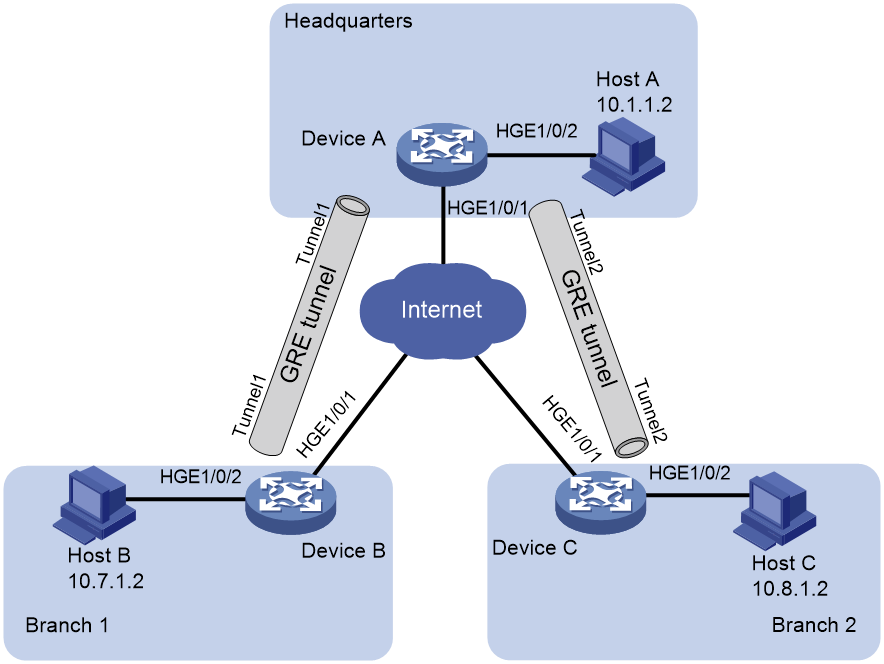
Table 1 Interface and IP address assignment
|
Device |
Interface |
IP address |
Device |
Interface |
IP address |
|
Device A |
HGE1/0/1 |
191.2.1.1/24 |
Device B |
HGE1/0/1 |
191.3.1.1/24 |
|
|
HGE1/0/2 |
10.1.1.1/24 |
|
HGE1/0/2 |
10.7.1.1/24 |
|
|
Tunnel1 |
10.5.1.1/24 |
|
Tunnel1 |
10.5.1.2/24 |
|
|
Tunnel2 |
10.6.1.1/24 |
|
|
|
|
Device C |
HGE1/0/1 |
191.4.1.1/24 |
|
|
|
|
|
HGE1/0/2 |
10.8.1.1/24 |
|
|
|
|
|
Tunnel2 |
10.6.1.2/24 |
|
|
|
Software versions used
This configuration example was created and verified on Release 3606.
Restrictions and guidelines
Encapsulated packets cannot be forwarded on Layer 3 according to the destination IP addresses and routing tables. You must create a service loopback group of the tunnel service type to loop encapsulated packets back to the forwarding module for Layer 3 forwarding.
By default, interfaces on the device are disabled (in ADM or Administratively Down state). To have an interface operate, you must use the undo shutdown command to enable that interface.
Procedures
Before configuring GRE and OSPF, configure an IPv4 routing protocol on the gateways so that they can reach one another. (Details not shown.)
Configuring Device A
# Configure HundredGigE 1/0/1.
<DeviceA> system-view
[DeviceA] interface hundredgige 1/0/1
[DeviceA-HundredGigE1/0/1] ip address 191.2.1.1 255.255.255.0
[DeviceA-HundredGigE1/0/1] quit
# Configure other interfaces in the same way HundredGigE 1/0/1 is configured. (Details not shown.)
# Create service loopback group 1, and specify its service type as Tunnel.
[DeviceA] service-loopback group 1 type tunnel
# Add HundredGigE 1/0/3 to service loopback group 1.
[DeviceA] interface HundredGigE 1/0/3
[DeviceA-HundredGigE1/0/3] port link-mode bridge
[DeviceA-HundredGigE1/0/3] port service-loopback group 1
[DeviceA-HundredGigE1/0/3] quit
# Create a tunnel interface Tunnel 1, and specify the tunnel mode as GRE/IPv4.
[DeviceA] interface tunnel 1 mode gre
# Configure an IP address for the tunnel interface Tunnel 1.
[DeviceA-Tunnel1] ip address 10.5.1.1 24
# Configure the source interface of the tunnel interface Tunnel 1 as HundredGigE 1/0/1.
[DeviceA-Tunnel1] source hundredgige 1/0/1
# Configure the destination address of the tunnel interface Tunnel 1 as the IP address of HundredGigE 1/0/1 on Device B.
[DeviceA-Tunnel1] destination 191.3.1.1
[DeviceA-Tunnel1] quit
# Create a tunnel interface Tunnel 2, and specify the tunnel mode as GRE/IPv4.
[DeviceA] interface tunnel 2 mode gre
# Configure an IP address for the tunnel interface Tunnel 2.
[DeviceA-Tunnel2] ip address 10.6.1.1 24
# Configure the source interface of the tunnel interface Tunnel 2 as HundredGigE 1/0/1.
[DeviceA-Tunnel2] source hundredgige 1/0/1
# Configure the destination address of the tunnel interface Tunnel 2 as the IP address of HundredGigE 1/0/1 on Device C.
[DeviceA-Tunnel2] destination 191.4.1.1
[DeviceA-Tunnel2] quit
# Configure the OSPF router ID as 10.6.1.1.
[DeviceA] router id 10.6.1.1
# Enable OSPF process 1.
[DeviceA] ospf 1
# Create OSPF area 0.
[DeviceA-ospf-1] area 0
# Enable OSPF on interfaces whose primary IP addresses are on network 10.1.1.0/24, 10.5.1.0/24, or 10.6.1.0/24 in area 0.
[DeviceA-ospf-1-area-0.0.0.0] network 10.1.1.0 0.0.0.255
[DeviceA-ospf-1-area-0.0.0.0] network 10.5.1.0 0.0.0.255
[DeviceA-ospf-1-area-0.0.0.0] network 10.6.1.0 0.0.0.255
Configuring Device B
# Configure HundredGigE 1/0/1.
<DeviceB> system-view
[DeviceB] interface hundredgige 1/0/1
[DeviceB-HundredGigE1/0/1] ip address 191.3.1.1 255.255.255.0
[DeviceB-HundredGigE1/0/1] quit
# Configure other interfaces in the same way HundredGigE 1/0/1 is configured. (Details not shown.)
# Create service loopback group 1, and specify its service type as Tunnel.
[DeviceB] service-loopback group 1 type tunnel
# Add HundredGigE 1/0/3 to service loopback group 1.
[DeviceB] interface HundredGigE 1/0/3
[DeviceB-HundredGigE1/0/3] port link-mode bridge
[DeviceB-HundredGigE1/0/3] port service-loopback group 1
[DeviceB-HundredGigE1/0/3] quit
# Create a tunnel interface Tunnel 1, and specify the tunnel mode as GRE/IPv4.
[DeviceB] interface tunnel 1 mode gre
# Configure an IP address for the tunnel interface Tunnel 1.
[DeviceB-Tunnel1] ip address 10.5.1.2 24
# Configure the source interface of the tunnel interface Tunnel 1 as HundredGigE 1/0/1.
[DeviceB-Tunnel1] source hundredgige 1/0/1
# Configure the destination address of the tunnel interface Tunnel 1 as the IP address of HundredGigE 1/0/1 on Device A.
[DeviceB-Tunnel1] destination 191.2.1.1
[DeviceB-Tunnel1] quit
# Configure the OSPF router ID as 10.7.1.1.
[DeviceB] router id 10.7.1.1
# Enable OSPF process 1.
[DeviceB] ospf 1
# Create OSPF area 0.
[DeviceB-ospf-1] area 0
# Enable OSPF on interfaces whose primary IP addresses are on network 10.7.1.0/24 or 10.5.1.0/24 in area 0.
[DeviceB-ospf-1-area-0.0.0.0] network 10.7.1.0 0.0.0.255
[DeviceB-ospf-1-area-0.0.0.0] network 10.5.1.0 0.0.0.255
Configuring Device C
# Configure HundredGigE 1/0/1.
<DeviceC> system-view
[DeviceC] interface hundredgige 1/0/1
[DeviceC-HundredGigE1/0/1] ip address 191.4.1.1 255.255.255.0
[DeviceC-HundredGigE1/0/1] quit
# Configure other interfaces in the same way HundredGigE 1/0/1 is configured. (Details not shown.)
# Create service loopback group 1, and specify its service type as Tunnel.
[DeviceC] service-loopback group 1 type tunnel
# Add HundredGigE 1/0/3 to service loopback group 1.
[DeviceC] interface HundredGigE 1/0/3
[DeviceC-HundredGigE1/0/3] port link-mode bridge
[DeviceC-HundredGigE1/0/3] port service-loopback group 1
[DeviceC-HundredGigE1/0/3] quit
# Create a tunnel interface Tunnel 2, and specify the tunnel mode as GRE/IPv4.
[DeviceC] interface tunnel 2 mode gre
# Configure an IP address for the tunnel interface Tunnel 2.
[DeviceC-Tunnel2] ip address 10.6.1.2 24
# Configure the source interface of the tunnel interface Tunnel 2 as HundredGigE 1/0/1.
[DeviceC-Tunnel2] source hundredgige 1/0/1
# Configure the destination address of the tunnel interface Tunnel 2 as the IP address of HundredGigE 1/0/1 on Device A.
[DeviceC-Tunnel2] destination 191.2.1.1
[DeviceC-Tunnel2] quit
# Configure the OSPF router ID as 10.8.1.1.
[DeviceC] router id 10.8.1.1
# Enable OSPF process 1.
[DeviceC] ospf 1
# Create OSPF area 0.
[DeviceC-ospf-1] area 0
# Enable OSPF on interfaces whose primary IP addresses are on network 10.8.1.0/24 or 10.6.1.0/24 in area 0.
[DeviceC-ospf-1-area-0.0.0.0] network 10.8.1.0 0.0.0.255
[DeviceC-ospf-1-area-0.0.0.0] network 10.6.1.0 0.0.0.255
Verifying the configuration
# Verify that Host A can ping Host B successfully.
C:\> ping 10.7.1.2
Pinging 10.7.1.2 with 32 bytes of data:
Reply from 10.7.1.2: bytes=32 time=19ms TTL=253
Reply from 10.7.1.2: bytes=32 time<1ms TTL=253
Reply from 10.7.1.2: bytes=32 time<1ms TTL=253
Reply from 10.7.1.2: bytes=32 time<1ms TTL=253
Ping statistics for 10.7.1.2:
Packets: Sent = 4, Received = 4, Lost = 0 (0% loss),
Approximate round trip times in milli-seconds:
Minimum = 0ms, Maximum = 19ms, Average = 4ms
# Verify that Host A can ping Host C successfully.
C:\> ping 10.8.1.2
Pinging 10.8.1.2 with 32 bytes of data:
Reply from 10.8.1.2: bytes=32 time=18ms TTL=253
Reply from 10.8.1.2: bytes=32 time<1ms TTL=253
Reply from 10.8.1.2: bytes=32 time<1ms TTL=253
Reply from 10.8.1.2: bytes=32 time<1ms TTL=253
Ping statistics for 10.8.1.2:
Packets: Sent = 4, Received = 4, Lost = 0 (0% loss),
Approximate round trip times in milli-seconds:
Minimum = 0ms, Maximum = 19ms, Average = 4ms
# Verify that Host B can ping Host C successfully.
C:\> ping 10.8.1.2
Pinging 10.8.1.2 with 32 bytes of data:
Reply from 10.8.1.2: bytes=32 time=20ms TTL=251
Reply from 10.8.1.2: bytes=32 time<1ms TTL=251
Reply from 10.8.1.2: bytes=32 time<1ms TTL=251
Reply from 10.8.1.2: bytes=32 time<1ms TTL=251
Ping statistics for 10.8.1.2:
Packets: Sent = 4, Received = 4, Lost = 0 (0% loss),
Approximate round trip times in milli-seconds:
Minimum = 0ms, Maximum = 19ms, Average = 4ms
Configuration files
· Device A
#
service-loopback group 1 type tunnel
#
interface HundredGigE1/0/1
ip address 191.2.1.1 255.255.255.0
#
interface HundredGigE1/0/2
ip address 10.1.1.1 255.255.255.0
#
interface HundredGigE1/0/3
port link-mode bridge
port service-loopback group 1
#
interface Tunnel1 mode gre
source HundredGigE1/0/1
destination 191.3.1.1
ip address 10.5.1.1 255.255.255.0
#
interface Tunnel2 mode gre
source HundredGigE1/0/1
destination 191.4.1.1
ip address 10.6.1.1 255.255.255.0
#
router id 10.6.1.1
#
ospf 1
area 0.0.0.0
network 10.1.1.0 0.0.0.255
network 10.5.1.0 0.0.0.255
network 10.6.1.0 0.0.0.255
#
· Device B
#
service-loopback group 1 type tunnel
#
interface HundredGigE1/0/1
ip address 191.3.1.1 255.255.255.0
#
interface HundredGigE1/0/2
ip address 10.7.1.1 255.255.255.0
#
interface HundredGigE1/0/3
port link-mode bridge
port service-loopback group 1
#
interface Tunnel1 mode gre
source HundredGigE1/0/1
destination 191.2.1.1
ip address 10.5.1.2 255.255.255.0
#
router id 10.7.1.1
#
ospf 1
area 0.0.0.0
network 10.7.1.0 0.0.0.255
network 10.5.1.0 0.0.0.255
#
· Device C
#
service-loopback group 1 type tunnel
#
interface HundredGigE1/0/1
ip address 191.4.1.1 255.255.255.0
#
interface HundredGigE1/0/2
ip address 10.8.1.1 255.255.255.0
#
interface HundredGigE1/0/3
port link-mode bridge
port service-loopback group 1
#
interface Tunnel2 mode gre
source HundredGigE1/0/1
destination 191.2.1.1
ip address 10.6.1.2 255.255.255.0
#
router id 10.8.1.1
#
ospf 1
area 0.0.0.0
network 10.8.1.0 0.0.0.255
network 10.6.1.0 0.0.0.255
#
Related documentation
· H3C S12500R Switch Router Series Layer 3—IP Routing Command Reference-R3606
· H3C S12500R Switch Router Series Layer 3—IP Routing Configuration Guide-R3606
· H3C S12500R Switch Router Series Layer 3—IP Services Command Reference-R3606
· H3C S12500R Switch Router Series Layer 3—IP Services Configuration Guide-R3606
