- Table of Contents
-
- H3C S12500R Ethernet Switch Router Series Config Examples-Release 36xx-6W100
- 01-Login Management Configuration Examples
- 02-RBAC Configuration Examples
- 03-Software Upgrade Examples
- 04-Ethernet Link Aggregation Configuration Examples
- 05-Port Isolation Configuration Examples
- 06-Spanning Tree Configuration Examples
- 07-VLAN Configuration Examples
- 08-VLAN Tagging Configuration Examples
- 09-DHCP Snooping Configuration Examples
- 10-Cross-Subnet Dynamic IP Address Allocation Configuration Examples
- 11-IPv6 over IPv4 Tunneling with OSPFv3 Configuration Examples
- 12-GRE Tunnel Configuration Examples
- 13-GRE with OSPF Configuration Examples
- 14-OSPF Configuration Examples
- 15-IS-IS Configuration Examples
- 16-BGP Configuration Examples
- 17-Policy-Based Routing Configuration Examples
- 18-OSPFv3 Configuration Examples
- 19-IPv6 IS-IS Configuration Examples
- 20-Routing Policy Configuration Examples
- 21-IGMP Snooping Configuration Examples
- 22-IGMP Configuration Examples
- 23-MLD Snooping Configuration Examples
- 24-Basic MPLS Configuration Examples
- 25-MPLS L3VPN Configuration Examples
- 26-ACL Configuration Examples
- 27-Control Plane-Based QoS Policy Configuration Examples
- 28-Traffic Policing Configuration Examples
- 29-GTS and Rate Limiting Configuration Examples
- 30-Priority Mapping and Queue Scheduling Configuration Examples
- 31-Traffic Filtering Configuration Examples
- 32-AAA Configuration Examples
- 33-SSH Configuration Examples
- 34-IP Source Guard Configuration Examples
- 35-Ethernet OAM Configuration Examples
- 36-CFD Configuration Examples
- 37-DLDP Configuration Examples
- 38-VRRP Configuration Examples
- 39-BFD Configuration Examples
- 40-NTP Configuration Examples
- 41-SNMP Configuration Examples
- 42-NQA Configuration Examples
- 43-Mirroring Configuration Examples
- 44-sFlow Configuration Examples
- 45-OpenFlow Configuration Examples
- 46-MAC Address Table Configuration Examples
- 47-Static Multicast MAC Address Entry Configuration Examples
- 48-IP Unnumbered Configuration Examples
- 49-Congestion Avoidance and Queue Scheduling Configuration Examples
- 50-Attack Protection Configuration Examples
- 51-Smart Link Configuration Examples
- 52-RRPP Configuration Examples
- 53-BGP Route Selection Configuration Examples
- 54-IS-IS Route Summarization Configuration Examples
- 55-MPLS OAM Configuration Examples
- 56-MPLS TE Configuration Examples
- 57-VXLAN Configuration Examples
- 58-NetStream Configuration Examples
- 59-EVPN-DCI over an MPLS L3VPN Network Configuration Examples
- 60-PTP Configuration Examples
- 61-S-MLAG Configuration Examples
- 62-MPLS SR Configuration Examples
- 63-Puppet Configuration Examples
- Related Documents
-
| Title | Size | Download |
|---|---|---|
| 50-Attack Protection Configuration Examples | 501.98 KB |
|
|
|
H3C S12500R Switch Router Series |
|
Attack Protection Configuration Examples |
|
|
Copyright © 2021 New H3C Technologies Co., Ltd. All rights reserved.
No part of this manual may be reproduced or transmitted in any form or by any means without prior written consent of New H3C Technologies Co., Ltd.
Except for the trademarks of New H3C Technologies Co., Ltd., any trademarks that may be mentioned in this document are the property of their respective owners.
The information in this document is subject to change without notice.
Contents
Example: Configuring link layer attack protection
Example: Configuring ARP attack protection
Example: Configuring network layer attack protection
Example: Configuring transport layer attack protection
Introduction
This document provides configuration examples of link layer attack protection, ARP attack protection, network layer attack protection, and transport layer attack protection, as defined in Table 1.
Table 1 Attack protection types
|
Attack protection types |
Description |
|
|
Link layer attack protection |
MAC address attack protection |
Prevents the attack of packets with different source MAC addresses or VLANs by configuring the maximum number of MAC addresses that an interface can learn. |
|
STP packet attack protection |
Provides protection measures such as BPDU guard, root guard, loop guard, and TC-BPDU guard. |
|
|
ARP attack protection |
ARP source suppression |
Prevents IP attack packets from fixed sources. |
|
ARP black hole routing |
Prevents IP attack packets from sources that are not fixed. |
|
|
ARP active acknowledgement |
Prevents user spoofing. |
|
|
Source MAC-based ARP attack detection |
Prevents ARP packet attacks from the same source MAC. |
|
|
ARP packet source MAC consistency check |
Prevents attacks from ARP packets whose source MAC address in the Ethernet header is different from the sender MAC address in the message body. |
|
|
Network layer attack protection |
uRPF check |
Protects a network against source spoofing attacks. |
|
TTL attack protection |
Prevents an attack by disabling sending ICMP time exceeded messages. |
|
|
Transport layer attack protection |
SYN flood attack protection |
Enables the server to return a SYN ACK message when it receives a TCP connection request, without establishing a half-open TCP connection. |
Prerequisites
The configuration examples in this document were created and verified in a lab environment, and all the devices were started with the factory default configuration. When you are working on a live network, make sure you understand the potential impact of every command on your network.
This document assumes that you have basic knowledge of attack protection.
Example: Configuring link layer attack protection
Network configuration
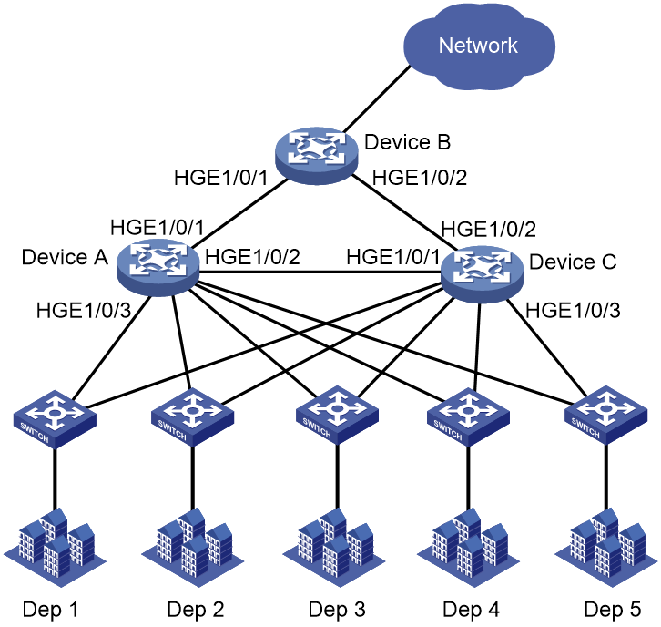
As shown in Figure 1, Device A, Device B, and Device C run MSTP. Device B acts as the root bridge, and HundredGigE 1/0/1 on Device C is blocked.
Configure the following features to prevent link layer attacks:
· Configure root guard on HundredGigE 1/0/1 and HundredGigE 1/0/2 of Device B for Device B to act as the root bridge.
· Configure loop guard on HundredGigE 1/0/2 of Device C to prevent temporary loops. The loop guard feature keeps the port in Discarding state in all MSTIs when it receives no BPDU.
· Configure BPDU guard on ports at the access side of Device A and Device C. The BPDU guard feature prevents the ports from performing spanning tree calculations when it receives forged BPDUs with a higher priority.
· Enable TC-BPDU guard on Device A, Device B, and Device C. The TC-BPDU guard feature prevents a large number of TC-BPDUs from affecting the network in a short time.
· Configure broadcast and multicast suppression on the designated ports of Device B and all ports on Device A and Device C. When incoming broadcast or multicast traffic exceeds the threshold (6400 pps), an interface discards broadcast or multicast packets until the traffic drops below the threshold.
Analysis
For the ports at the access side of Device A and Device C to rapidly transit to the forwarding state, use the stp edged-port command to configure these ports as edge ports.
This example uses HundredGigE 1/0/3 to illustrate the configuration on the ports at the access side on Device A and Device C.
Software versions used
This configuration example was created and verified on Release 3606.
Restrictions and guidelines
On a port, the loop guard feature is mutually exclusive with the root guard feature or the edge port setting.
Do not configure the loop guard feature on ports at the access side. Otherwise, the ports stay in Discarding state in all MSTIs because they cannot receive BPDUs.
By default, interfaces on the device are disabled (in ADM or Administratively Down state). To have an interface operate, you must use the undo shutdown command to enable that interface.
Procedures
Configuring Device B
# Specify IP addresses for interfaces. (Details not shown.)
# Configure root guard on HundredGigE 1/0/1 and HundredGigE 1/0/2.
<DeviceB> system-view
[DeviceB] interface range hundredgige 1/0/1 to hundredgige 1/0/2
[DeviceB-if-range] port link-mode bridge
[DeviceB-if-range] stp root-protection
[DeviceB-if-range] quit
# Configure TC-BPDU guard.
[DeviceB] stp tc-protection
[DeviceB] stp tc-protection threshold 10
# Configure broadcast and multicast suppression on HundredGigE 1/0/1 and HundredGigE 1/0/2.
[DeviceB] interface range hundredgige 1/0/1 to hundredgige 1/0/2
[DeviceB-if-range] broadcast-suppression pps 6400
[DeviceB-if-range] multicast-suppression pps 6400
[DeviceB-if-range] quit
Configuring Device A
# Specify IP addresses for interfaces. (Details not shown.)
# Configure each interface to operate in Later 2 mode.
<DeviceA> system-view
[DeviceA] interface range hundredgige 1/0/1 to hundredgige 1/0/3
[DeviceA-if-range] port link-mode bridge
[DeviceA-if-range] quit
# Configure STP BPDU guard.
[DeviceA] stp bpdu-protection
# Configure HundredGigE 1/0/3 as an edge port.
[DeviceA] interface hundredgige 1/0/3
[DeviceA-HundredGigE1/0/3] stp edged-port
[DeviceA-HundredGigE1/0/3] quit
# Configure TC-BPDU guard.
[DeviceA] stp tc-protection
[DeviceA] stp tc-protection threshold 10
# Configure broadcast and multicast suppression on all ports.
[DeviceA] interface range hundredgige 1/0/1 to hundredgige 1/0/3
[DeviceA-if-range] broadcast-suppression pps 6400
[DeviceA-if-range] multicast-suppression pps 6400
[DeviceA-if-range] quit
Configuring Device C
# Specify IP addresses for interfaces. (Details not shown.)
# Configure each interface to operate in Later 2 mode.
<DeviceC> system-view
[DeviceC] interface range hundredgige 1/0/1 to hundredgige 1/0/3
[DeviceC-if-range] port link-mode bridge
[DeviceC-if-range] quit
# Configure STP BPDU guard.
[DeviceC] stp bpdu-protection
# Configure HundredGigE 1/0/3 as an edge port.
[DeviceC] interface hundredgige 1/0/3
[DeviceC-HundredGigE1/0/3] stp edged-port
[DeviceC-HundredGigE1/0/3] quit
# Configure loop guard on HundredGigE 1/0/2.
[DeviceC] interface hundredgige 1/0/2
[DeviceC-HundredGigE1/0/2] stp loop-protection
[DeviceC-HundredGigE1/0/2] quit
# Configure TC-BPDU guard.
[DeviceC] stp tc-protection
[DeviceC] stp tc-protection threshold 10
# Configure broadcast and multicast suppression on all ports.
[DeviceC] interface range hundredgige 1/0/1 to hundredgige 1/0/3
[DeviceC-if-range] broadcast-suppression pps 6400
[DeviceC-if-range] multicast-suppression pps 6400
[DeviceC-if-range] quit
Verifying the configuration
# Verify that the edge ports go down after they receives STP BPDUs. (Details not shown.)
# Bring the edge ports up by using the undo shutdown command. (Details not shown.)
# Verify that the root bridge ID of Device B does not change and that the STP topology remains stable after STP BPDUs with higher priority are sent to the Device B. (Details not shown.)
# Verify that the devices do not refresh the FIB table frequently and that no serious packet loss occurs after a large number of TC BPDUs are sent to the devices. (Details not shown.)
# Verify that the uplink ports are not flooded after a large number of broadcasts are sent to the edge ports on device A and Device C. (Details not shown.)
Configuration files
· Device A:
#
stp bpdu-protection
stp tc-protection threshold 10
#
interface HundredGigE 1/0/1
port link-mode bridge
broadcast-suppression pps 6400
multicast-suppression pps 6400
#
interface HundredGigE 1/0/2
port link-mode bridge
broadcast-suppression pps 6400
multicast-suppression pps 6400
#
interface HundredGigE 1/0/3
port link-mode bridge
stp edged-port
broadcast-suppression pps 6400
multicast-suppression pps 6400
#
· Device B:
#
stp tc-protection threshold 10
#
interface HundredGigE 1/0/1
port link-mode bridge
stp root-protection
broadcast-suppression pps 6400
multicast-suppression pps 6400
#
interface HundredGigE 1/0/2
port link-mode bridge
stp root-protection
broadcast-suppression pps 6400
multicast-suppression pps 6400
#
· Device C:
#
stp bpdu-protection
stp tc-protection threshold 10
#
interface HundredGigE 1/0/1
port link-mode bridge
broadcast-suppression pps 6400
multicast-suppression pps 6400
#
interface HundredGigE 1/0/2
port link-mode bridge
stp loop-protection
broadcast-suppression pps 6400
multicast-suppression pps 6400
#
interface HundredGigE 1/0/3
port link-mode bridge
stp edged-port
broadcast-suppression pps 6400
multicast-suppression pps 6400
#
Example: Configuring ARP attack protection
Network configuration
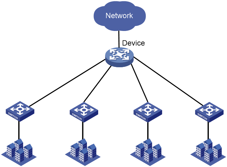
As shown in Figure 2, the device is the gateway for the internal network. Configure ARP attack protection on the device to prevent ARP attacks.
Software versions used
This configuration example was created and verified on Release 3606.
Procedures
# Specify IP addresses for interfaces. (Details not shown.)
# Enable ARP source suppression.
<Device> system-view
[Device] arp source-suppression enable
# Configure the device to accept a maximum of 8 unresolvable packets per source IP address in 5 seconds.
[Device] arp source-suppression limit 8
# Enable ARP black hole routing to prevent unresolvable IP packet attacks.
[Device] arp resolving-route enable
# Enable ARP active acknowledgment to prevent user spoofing.
[Device] arp active-ack enable
# Configure source MAC-based ARP attack detection to prevent ARP packet attacks from the same source MAC.
[Device] arp source-mac filter
[Device] arp source-mac threshold 25
# Enable ARP packet source MAC address consistency check to prevent attacks from ARP packets with different source MAC addresses in the Ethernet header and in the message body.
[Device] arp valid-check enable
Verifying the configuration
1. Verify that ARP attack protection functions on the device:
# Send ARP attack packets to the device. (Details not shown.)
# Verify that the CPU usage does not surge. (Details not shown.)
2. Verify that each ARP attack protection feature functions on the device (this example uses the ARP source suppression feature):
# Send the device 20 forged packets with the same source IP address and unresolvable destination IP addresses. (Details not shown.)
# Verify that the device stops resolving the packets after receiving 8 forged packets within 5 seconds. (Details not shown.)
# Verify the ARP source suppression configuration.
[Device] display arp source-suppression
ARP source suppression is enabled
Current suppression limit: 8
Current cache length: 16
Configuration files
#
arp valid-check enable
arp source-mac filter
arp source-mac threshold 25
arp active-ack enable
arp source-suppression enable
arp source-suppression limit 8
#
Example: Configuring network layer attack protection
Network configuration
As shown in Figure 3, Device A is the gateway for the internal network. To protect Device A against IP packet attacks from internal and external networks, configure the following network layer attack protection features:
· Configure strict uRPF check to prevent source address spoofing attacks.
· Disabling sending ICMP time exceeded messages. The device will not be flooded by ICMP time exceeded messages when receiving a large number of packets with TTL set to 1.

Software versions used
This configuration example was created and verified on Release 3606.
Restrictions and guidelines
After you disable sending ICMP time exceeded messages, the tracert feature will not be available.
Do no configure both uRPF in strict mode and ECMP routes. A violation might cause that service packets forwarded based on ECMP routes are mistakenly dropped.
By default, interfaces on the device are disabled (in ADM or Administratively Down state). To have an interface operate, you must use the undo shutdown command to enable that interface.
Procedures
# Specify IP addresses for interfaces. (Details not shown.)
# Enable strict uRPF check.
[DeviceA] ip urpf strict
# Disable sending ICMP time exceeded messages. Sending ICMP time exceeded messages is disabled by default.
[DeviceA] undo ip ttl-expires enable
Verifying the configuration
1. Verify that Device A can prevent source address spoofing attacks:
# Verify that Device A can filter out packets with forged source IP addresses. (Details not shown.)
# Verify the uRPF configuration.
[DeviceA] display ip urpf
Global uRPF configuration information:
Check type: strict
2. Verify that TTL attack protection functions on Device A:
# Enable ICMP debugging by executing the debugging ip icmp command on Device A. (Details not shown.)
# Use a PC to send packets in which the TTL is 1 to Device A. (Details not shown.)
# Verify that Device A does not display any debugging information and that the PC does not receive any ICMP time exceeded messages. (Details not shown.)
# Enable sending ICMP time exceeded messages and send packets in which the TTL is 1 to Device A. (Details not shown.)
# Verify that Device A responds with ICMP time exceeded messages.
<DeviceA> *Aug 14 16:43:31:068 2016 NM-3 SOCKET/7/ICMP: Slot=2;
Time(s):1371221011 ICMP Output:
ICMP Packet: src = 6.0.0.1, dst = 202.101.0.2
type = 11, code = 0 (ttl-exceeded)
Original IP: src = 202.101.0.2, dst = 192.168.0.2
proto = 253, first 8 bytes = 00000000 00000000
Configuration files
#
ip urpf strict
#
Example: Configuring transport layer attack protection
Network configuration
As shown in Figure 4, the device is the gateway for the internal network. Configure SYN Cookie protection on the device to protect against SYN flood attacks. With this feature enabled, the device responds to a SYN packet with a SYN ACK packet without establishing a TCP semi-connection. The device establishes a TCP connection only when it receives an ACK packet from the sender.

Software versions used
This configuration example was created and verified on Release 3606.
By default, interfaces on the device are disabled (in ADM or Administratively Down state). To have an interface operate, you must use the undo shutdown command to enable that interface.
Procedures
# Specify IP addresses for interfaces. (Details not shown.)
# Enable SYN Cookie.
<Device> system-view
[Device] tcp syn-cookie enable
Verifying the configuration
# Verify that the device does not have any TCP semi-connections. The state "SYN_RECEIVED" represents semi-connections.
[Device] display tcp
*: TCP connection with authentication
Local Addr:port Foreign Addr:port State Slot PCB
0.0.0.0:21 0.0.0.0:0 LISTEN 1 0xffffffffffffff9
d
0.0.0.0:23 0.0.0.0:0 LISTEN 1 0xffffffffffffff9
f
192.168.2.88:23 192.168.2.79:2197 ESTABLISHED 1 0xffffffffffffffa
3
192.168.2.88:23 192.168.2.89:2710 ESTABLISHED 1 0xffffffffffffffa
2
192.168.2.88:23 192.168.2.110:50199 ESTABLISHED 1 0xffffffffffffffa
5
Configuration files
#
tcp syn-cookie enable
#
Related documentation
· H3C S12500R Switch Router Series Layer 2—LAN Switching Command Reference-R3606
· H3C S12500R Switch Router Series Layer 2—LAN Switching Configuration Guide-R3606
· H3C S12500R Switch Router Series Layer 3—IP Services Command Reference-R3606
· H3C S12500R Switch Router Series Layer 3—IP Services Configuration Guide-R3606
· H3C S12500R Switch Router Series Security Command Reference-R3606
· H3C S12500R Switch Router Series Security Configuration Guide-R3606
