- Table of Contents
-
- H3C S12500R Ethernet Switch Router Series Config Examples-Release 36xx-6W100
- 01-Login Management Configuration Examples
- 02-RBAC Configuration Examples
- 03-Software Upgrade Examples
- 04-Ethernet Link Aggregation Configuration Examples
- 05-Port Isolation Configuration Examples
- 06-Spanning Tree Configuration Examples
- 07-VLAN Configuration Examples
- 08-VLAN Tagging Configuration Examples
- 09-DHCP Snooping Configuration Examples
- 10-Cross-Subnet Dynamic IP Address Allocation Configuration Examples
- 11-IPv6 over IPv4 Tunneling with OSPFv3 Configuration Examples
- 12-GRE Tunnel Configuration Examples
- 13-GRE with OSPF Configuration Examples
- 14-OSPF Configuration Examples
- 15-IS-IS Configuration Examples
- 16-BGP Configuration Examples
- 17-Policy-Based Routing Configuration Examples
- 18-OSPFv3 Configuration Examples
- 19-IPv6 IS-IS Configuration Examples
- 20-Routing Policy Configuration Examples
- 21-IGMP Snooping Configuration Examples
- 22-IGMP Configuration Examples
- 23-MLD Snooping Configuration Examples
- 24-Basic MPLS Configuration Examples
- 25-MPLS L3VPN Configuration Examples
- 26-ACL Configuration Examples
- 27-Control Plane-Based QoS Policy Configuration Examples
- 28-Traffic Policing Configuration Examples
- 29-GTS and Rate Limiting Configuration Examples
- 30-Priority Mapping and Queue Scheduling Configuration Examples
- 31-Traffic Filtering Configuration Examples
- 32-AAA Configuration Examples
- 33-SSH Configuration Examples
- 34-IP Source Guard Configuration Examples
- 35-Ethernet OAM Configuration Examples
- 36-CFD Configuration Examples
- 37-DLDP Configuration Examples
- 38-VRRP Configuration Examples
- 39-BFD Configuration Examples
- 40-NTP Configuration Examples
- 41-SNMP Configuration Examples
- 42-NQA Configuration Examples
- 43-Mirroring Configuration Examples
- 44-sFlow Configuration Examples
- 45-OpenFlow Configuration Examples
- 46-MAC Address Table Configuration Examples
- 47-Static Multicast MAC Address Entry Configuration Examples
- 48-IP Unnumbered Configuration Examples
- 49-Congestion Avoidance and Queue Scheduling Configuration Examples
- 50-Attack Protection Configuration Examples
- 51-Smart Link Configuration Examples
- 52-RRPP Configuration Examples
- 53-BGP Route Selection Configuration Examples
- 54-IS-IS Route Summarization Configuration Examples
- 55-MPLS OAM Configuration Examples
- 56-MPLS TE Configuration Examples
- 57-VXLAN Configuration Examples
- 58-NetStream Configuration Examples
- 59-EVPN-DCI over an MPLS L3VPN Network Configuration Examples
- 60-PTP Configuration Examples
- 61-S-MLAG Configuration Examples
- 62-MPLS SR Configuration Examples
- 63-Puppet Configuration Examples
- Related Documents
-
| Title | Size | Download |
|---|---|---|
| 05-Port Isolation Configuration Examples | 57.60 KB |
|
|
|
H3C S12500R Switch Router Series |
|
Port Isolation Configuration Examples |
|
|
Copyright © 2021 New H3C Technologies Co., Ltd. All rights reserved.
No part of this manual may be reproduced or transmitted in any form or by any means without prior written consent of New H3C Technologies Co., Ltd.
Except for the trademarks of New H3C Technologies Co., Ltd., any trademarks that may be mentioned in this document are the property of their respective owners.
The information in this document is subject to change without notice.
Introduction
This document provides port isolation configuration examples.
Prerequisites
This document is not restricted to specific software or hardware versions.
The configuration examples in this document were created and verified in a lab environment, and all the devices were started with the factory default configuration. When you are working on a live network, make sure you understand the potential impact of every command on your network.
This document assumes that you have basic knowledge of port isolation.
General restrictions and guidelines
You cannot assign the member ports of a service loopback group to an isolation group. When you assign the member ports of an isolation group to a service loopback group, the port isolation settings are removed from these ports.
Example: Configuring port isolation
Network configuration
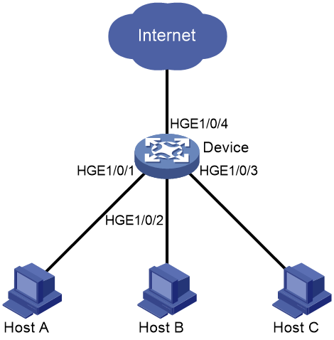
As shown in Figure 1:
· LAN users Host A, Host B, and Host C are connected to HundredGigE 1/0/1, HundredGigE 1/0/2, and HundredGigE 1/0/3 on the device, respectively.
· The device is connected to the Internet through HundredGigE 1/0/4.
Configure the device to provide Internet access for all the hosts, and isolate them from one another.
Software versions used
This configuration example was created and verified on R3606.
Restrictions and guidelines
By default, interfaces on the device are disabled (in ADM or Administratively Down state). To have an interface operate, you must use the undo shutdown command to enable that interface.
Procedures
# Configure HundredGigE1/0/1, HundredGigE1/0/2, and HundredGigE1/0/3 to operate in bridge mode.
<Device> system-view
[Device] interface range hundredgige 1/0/1 to hundredgige 1/0/3
[Device-if-range] port link-mode bridge
[Device-if-range] quit
# Assign HundredGigE 1/0/1, HundredGigE 1/0/2, HundredGigE 1/0/3 to the isolation group.
<Device> system-view
[Device] interface hundredgige 1/0/1
[Device-HundredGigE1/0/1] port-isolate enable
[Device-HundredGigE1/0/1] quit
[Device] interface hundredgige 1/0/2
[Device-HundredGigE1/0/2] port-isolate enable
[Device-HundredGigE1/0/2] quit
[Device] interface hundredgige 1/0/3
[Device-HundredGigE1/0/3] port-isolate enable
[Device-HundredGigE1/0/3] quit
Verifying the configuration
# Display information about the isolation group.
[Device] display port-isolate group
Port isolation group information:
Group ID: 1
Group members:
HundredGigE1/0/1
HundredGigE1/0/2
HundredGigE1/0/3
The output shows that HundredGigE 1/0/1, HundredGigE 1/0/2, HundredGigE 1/0/3 are in the isolation group. As a result, Host A, Host B, and Host C are isolated from one another at Layer 2.
Configuration files
#
interface HundredGigE1/0/1
port link-mode bridge
port-isolate enable
#
interface HundredGigE1/0/2
port link-mode bridge
port-isolate enable
#
interface HundredGigE1/0/3
port link-mode bridge
port-isolate enable
#
Related documentation
· H3C S12500R Switch Router Series Layer 2—LAN Switching Command Reference-R3606
· H3C S12500R Switch Router Series Layer 2—LAN Switching Configuration Guide-R3606
