- Table of Contents
-
- H3C S12500R Ethernet Switch Router Series Config Examples-Release 36xx-6W100
- 01-Login Management Configuration Examples
- 02-RBAC Configuration Examples
- 03-Software Upgrade Examples
- 04-Ethernet Link Aggregation Configuration Examples
- 05-Port Isolation Configuration Examples
- 06-Spanning Tree Configuration Examples
- 07-VLAN Configuration Examples
- 08-VLAN Tagging Configuration Examples
- 09-DHCP Snooping Configuration Examples
- 10-Cross-Subnet Dynamic IP Address Allocation Configuration Examples
- 11-IPv6 over IPv4 Tunneling with OSPFv3 Configuration Examples
- 12-GRE Tunnel Configuration Examples
- 13-GRE with OSPF Configuration Examples
- 14-OSPF Configuration Examples
- 15-IS-IS Configuration Examples
- 16-BGP Configuration Examples
- 17-Policy-Based Routing Configuration Examples
- 18-OSPFv3 Configuration Examples
- 19-IPv6 IS-IS Configuration Examples
- 20-Routing Policy Configuration Examples
- 21-IGMP Snooping Configuration Examples
- 22-IGMP Configuration Examples
- 23-MLD Snooping Configuration Examples
- 24-Basic MPLS Configuration Examples
- 25-MPLS L3VPN Configuration Examples
- 26-ACL Configuration Examples
- 27-Control Plane-Based QoS Policy Configuration Examples
- 28-Traffic Policing Configuration Examples
- 29-GTS and Rate Limiting Configuration Examples
- 30-Priority Mapping and Queue Scheduling Configuration Examples
- 31-Traffic Filtering Configuration Examples
- 32-AAA Configuration Examples
- 33-SSH Configuration Examples
- 34-IP Source Guard Configuration Examples
- 35-Ethernet OAM Configuration Examples
- 36-CFD Configuration Examples
- 37-DLDP Configuration Examples
- 38-VRRP Configuration Examples
- 39-BFD Configuration Examples
- 40-NTP Configuration Examples
- 41-SNMP Configuration Examples
- 42-NQA Configuration Examples
- 43-Mirroring Configuration Examples
- 44-sFlow Configuration Examples
- 45-OpenFlow Configuration Examples
- 46-MAC Address Table Configuration Examples
- 47-Static Multicast MAC Address Entry Configuration Examples
- 48-IP Unnumbered Configuration Examples
- 49-Congestion Avoidance and Queue Scheduling Configuration Examples
- 50-Attack Protection Configuration Examples
- 51-Smart Link Configuration Examples
- 52-RRPP Configuration Examples
- 53-BGP Route Selection Configuration Examples
- 54-IS-IS Route Summarization Configuration Examples
- 55-MPLS OAM Configuration Examples
- 56-MPLS TE Configuration Examples
- 57-VXLAN Configuration Examples
- 58-NetStream Configuration Examples
- 59-EVPN-DCI over an MPLS L3VPN Network Configuration Examples
- 60-PTP Configuration Examples
- 61-S-MLAG Configuration Examples
- 62-MPLS SR Configuration Examples
- 63-Puppet Configuration Examples
- Related Documents
-
| Title | Size | Download |
|---|---|---|
| 38-VRRP Configuration Examples | 426.71 KB |
|
|
|
H3C S12500R Switch Router Series |
|
VRRP Configuration Examples |
|
|
Copyright © 2021 New H3C Technologies Co., Ltd. All rights reserved.
No part of this manual may be reproduced or transmitted in any form or by any means without prior written consent of New H3C Technologies Co., Ltd.
Except for the trademarks of New H3C Technologies Co., Ltd., any trademarks that may be mentioned in this document are the property of their respective owners.
The information in this document is subject to change without notice.
Contents
Example: Configuring a single IPv4 VRRP group
Example: Configuring multiple IPv4 VRRP groups
Example: Configuring IPv4 VRRP load balancing
Example: Configuring a single IPv6 VRRP group
Example: Configuring multiple IPv6 VRRP groups
Example: Configuring IPv6 VRRP load balancing
Example: Configuring VRRP with Ethernet link aggregation
Introduction
This document provides VRRP configuration examples.
Prerequisites
This document is not restricted to specific software or hardware versions.
The configuration examples in this document were created and verified in a lab environment, and all the devices were started with the factory default configuration. When you are working on a live network, make sure you understand the potential impact of every command on your network.
This document assumes that you have basic knowledge of VRRP, STP, IPsec, and Ethernet link aggregation.
Example: Configuring a single IPv4 VRRP group
Network configuration
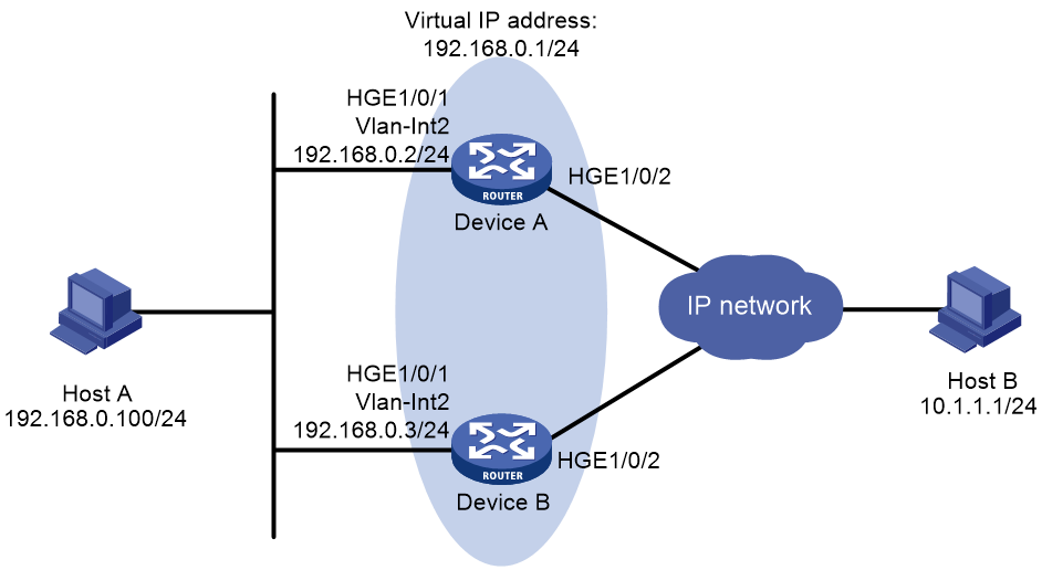
As shown in Figure 1, configure a VRRP group on Device A and Device B as the gateway for Host A to meet the following requirements:
· Device A operates as the master to forward packets from Host A to the external network.
· If Device A or its uplink interface fails, Host A can access the external network through Device B.
Analysis
To meet the network requirements, you must perform the following tasks:
· For Device A to become the master when it recovers from a failure, configure the preemptive mode for the VRRP group.
· For Device A to decrease its priority and become a backup when its uplink interface fails, configure VRRP tracking on Device A.
· To avoid frequent role change in the VRRP group, set a preemption delay.
Software versions used
This configuration example was created and verified on R3606.
Restrictions and guidelines
When you configure a single VRRP group, follow these restrictions and guidelines:
· The virtual IP address of a VRRP group cannot be any of the following addresses:
¡ All-zero address (0.0.0.0).
¡ Broadcast address (255.255.255.255).
¡ Loopback address.
¡ IP address of other than Class A, Class B, and Class C.
¡ Invalid IP address (for example, 0.0.0.1).
· For Host A to access the external network, make sure the following IP addresses are on the same subnet:
¡ The virtual IP address of the VRRP group.
¡ The downlink interface IP addresses of the VRRP group members.
· IPv4 VRRP can use VRRPv2 or VRRPv3 (default version). For a VRRP group to operate correctly, make sure the VRRP versions on all devices in the VRRP group are the same.
· Removal of the VRRP group on the IP address owner causes IP address collision. To avoid a collision, change the IP address of the interface on the IP address owner before you remove the VRRP group from the interface.
· Configure the same virtual IP addresses for each device in the VRRP group.
· Make sure the decreased priority of the master is lower than the priority of all the other devices in the VRRP group. Another device in the group can then be elected as the master.
· By default, interfaces on the device are disabled (in ADM or Administratively Down state). To have an interface operate, you must use the undo shutdown command to enable that interface.
· The physical interfaces in this example must operate at Layer 2. By default, the interfaces on the device operate at Layer 3. You must use the port link-mode command to change the link mode of the interfaces to Layer 2.
Procedures
Configuring Device A
# Create VLAN 2, and assign HundredGigE 1/0/1 to VLAN 2.
<DeviceA> system-view
[DeviceA] interface hundredgige 1/0/1
[DeviceA-HundredGigE1/0/1] undo shutdown
[DeviceA-HundredGigE1/0/1] quit
[DeviceA] vlan 2
[DeviceA-vlan2] port hundredgige 1/0/1
[DeviceA-vlan2] quit
[DeviceA] interface vlan-interface 2
[DeviceA-Vlan-interface2] ip address 192.168.0.2 24
# Create VLAN-interface 2, and assign an IP address to the VLAN interface.
[DeviceA] interface vlan-interface 2
[DeviceA-Vlan-interface2] ip address 192.168.0.2 24
# Create VRRP group 1, and set its virtual IP address to 192.168.0.1.
[DeviceA-Vlan-interface2] vrrp vrid 1 virtual-ip 192.168.0.1
# Set the priority of Device A to 110 in VRRP group 1. Device A has a higher priority than Device B in VRRP group 1, so Device A can become the master.
[DeviceA-Vlan-interface2] vrrp vrid 1 priority 110
# Configure Device A to operate in preemptive mode, and set the preemption delay to 5 seconds.
[DeviceA-Vlan-interface2] vrrp vrid 1 preempt-mode delay 500
[DeviceA-Vlan-interface2] quit
# Create track entry 1 to monitor the link status of the uplink interface HundredGigE 1/0/2.
[DeviceA] track 1 interface hundredgige 1/0/2
[DeviceA-track-1] quit
# Associate VRRP group 1 with track entry 1 to decrease the weight of Device A by 50 when the track entry transits to Negative.
[DeviceA] interface vlan-interface 2
[DeviceA-Vlan-interface2] vrrp vrid 1 track 1 priority reduced 50
[DeviceA-Vlan-interface2] quit
Configuring Device B
# Create VLAN 2, and assign HundredGigE 1/0/1 to VLAN 2.
<DeviceB> system-view
[DeviceB] interface hundredgige 1/0/1
[DeviceB-HundredGigE1/0/1] undo shutdown
[DeviceB-HundredGigE1/0/1] quit
[DeviceB] vlan 2
[DeviceB-vlan2] port hundredgige 1/0/1
[DeviceB-vlan2] quit
# Create VLAN-interface 2, and assign an IP address to the VLAN interface.
[DeviceB] interface vlan-interface 2
[DeviceB-Vlan-interface2] ip address 192.168.0.3 24
# Create VRRP group 1, and set its virtual IP address to 192.168.0.1.
[DeviceB-Vlan-interface2] vrrp vrid 1 virtual-ip 192.168.0.1
# Set the priority of Device B to 100 in VRRP group 1.
[DeviceB-Vlan-interface2] vrrp vrid 1 priority 100
# Configure Device B to operate in preemptive mode, and set the preemption delay to 5 seconds.
[DeviceB-Vlan-interface2] vrrp vrid 1 preempt-mode delay 500
[DeviceB-Vlan-interface2] quit
Verifying the configuration
1. Verify that Host A can ping Host B. (Details not shown.)
2. Verify that Device A is operating as the master in VRRP group 1 to forward packets from Host A to Host B.
# Display detailed information about VRRP group 1 on Device A.
[DeviceA] display vrrp verbose
IPv4 Virtual Router Information:
Running mode : Standard
Total number of virtual routers : 1
Interface Vlan-interface2
VRID : 1 Adver Timer : 100 centiseconds
Admin Status : Up State : Master
Config Pri : 110 Running Pri : 110
Preempt Mode : Yes Delay Time : 500 centiseconds
Auth Type : None
Virtual IP : 192.168.0.1
Virtual MAC : 0000-5e00-0101
Master IP : 192.168.0.2
VRRP Track Information:
Track Object : 1 State : Positive Pri Reduced : 50
# Display detailed information about VRRP group 1 on Device B.
[DeviceB] display vrrp verbose
IPv4 Virtual Router Information:
Running mode : Standard
Total number of virtual routers : 1
Interface Vlan-interface2
VRID : 1 Adver Timer : 100 centiseconds
Admin Status : Up State : Backup
Config Pri : 100 Running Pri : 100
Preempt Mode : Yes Delay Time : 500 centiseconds
Become Master : 401ms left
Auth Type : None
Virtual IP : 192.168.0.1
Virtual MAC : 0000-5e00-0101
Master IP : 192.168.0.2
3. Disconnect the link between Host A and Device A, and verify that Host A can still ping Host B. (Details not shown.)
4. Verify that Device B takes over to forward packets from Host A to Host B when Device A fails.
[DeviceB] display vrrp verbose
IPv4 Virtual Router Information:
Running mode : Standard
Total number of virtual routers : 1
Interface Vlan-interface2
VRID : 1 Adver Timer : 100
Admin Status : Up State : Master
Config Pri : 100 Running Pri : 100
Preempt Mode : Yes Delay Time : 500
Auth Type : None
Virtual IP : 192.168.0.1
Virtual MAC : 0000-5e00-0101
Master IP : 192.168.0.3
5. Verify that Device A becomes the master to forward packets from Host A to Host B after Device A recovers.
[DeviceA] display vrrp verbose
IPv4 Virtual Router Information:
Running mode : Standard
Total number of virtual routers : 1
Interface Vlan-interface2
VRID : 1 Adver Timer : 100
Admin Status : Up State : Master
Config Pri : 110 Running Pri : 110
Preempt Mode : Yes Delay Time : 500
Auth Type : None
Virtual IP : 192.168.0.1
Virtual MAC : 0000-5e00-0101
Master IP : 192.168.0.2
VRRP Track Information:
Track Object : 1 State : Positive Pri Reduced : 50
Configuration files
· Device A:
#
vlan 2
#
interface Vlan-interface2
ip address 192.168.0.1 255.255.255.0
vrrp vrid 1 virtual-ip 192.168.0.2
vrrp vrid 1 priority 110
vrrp vrid 1 preempt-mode delay 500
vrrp vrid 1 track 1 priority reduced 50
#
interface Vlan-interface3
#
interface HundredGigE1/0/1
port link-mode bridge
port access vlan 2
#
interface HundredGigE1/0/2
port link-mode bridge
port access vlan 3
#
track 1 interface HundredGigE1/0/2
#
· Device B:
#
vlan 2
#
interface Vlan-interface2
ip address 192.168.0.1 255.255.255.0
vrrp vrid 1 virtual-ip 192.168.0.2
vrrp vrid 1 priority 100
vrrp vrid 1 preempt-mode delay 500
#
interface HundredGigE1/0/1
port link-mode bridge
port access vlan 2
#
Example: Configuring multiple IPv4 VRRP groups
Network configuration
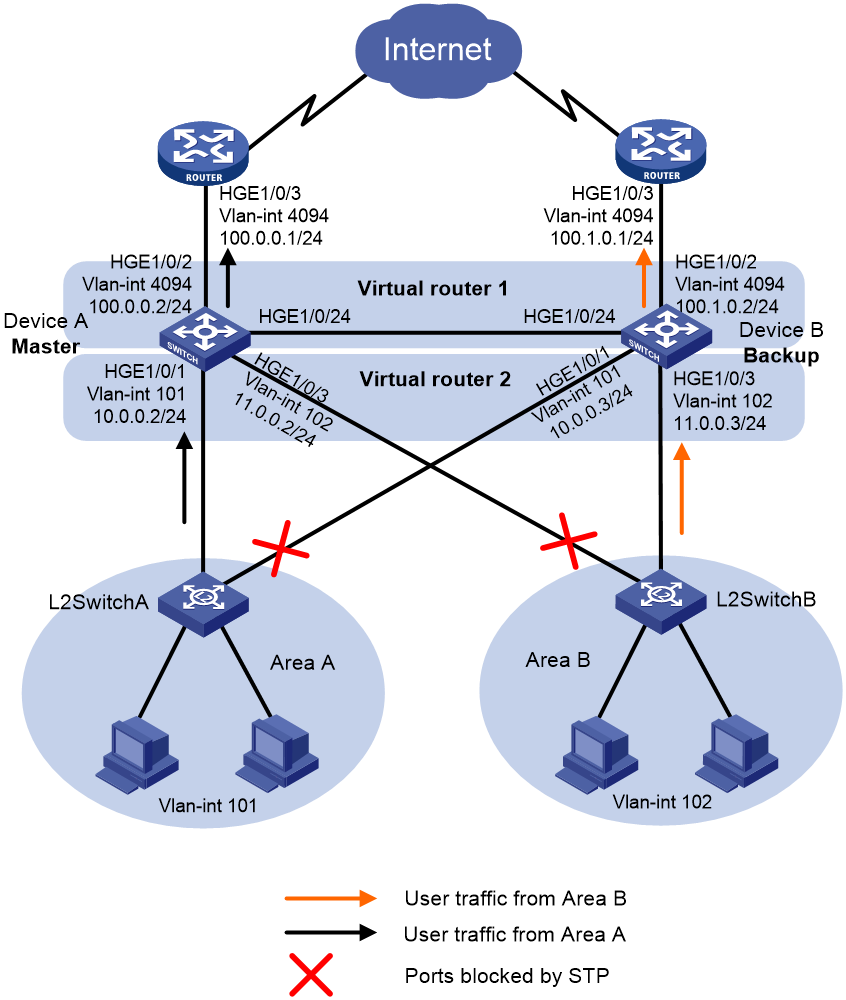
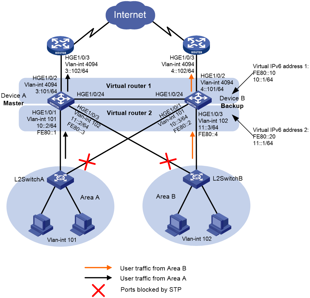
As shown in Figure 2, configure two VRRP groups on Device A and Device B as gateways for internal hosts to meet the following requirements:
· Device A operates as the master of VRRP group 1 to forward packets from Area A, and Device B operates as the master of VRRP group 2 to forward packets from Area B. When one of the devices fails, the other device provides gateway service for both areas.
· If the uplink interface of one device fails, hosts can access the external network through the other device.
Analysis
To meet the network requirements, you must perform the following tasks:
· To avoid frequent role change in the VRRP group, set a preemption delay.
· To avoid loops between Device A, Device B, and the Layer 2 switches, use the spanning tree feature to block a port in the two VRRP groups.
Software versions used
This configuration example was created and verified on R3606.
Restrictions and guidelines
When you configure multiple VRRP groups, follow these restrictions and guidelines:
· The virtual IP address of a VRRP group cannot be any of the following addresses:
¡ All-zero address (0.0.0.0).
¡ Broadcast address (255.255.255.255).
¡ Loopback address.
¡ IP address of other than Class A, Class B, and Class C.
¡ Invalid IP address (for example, 0.0.0.1).
· For the hosts in both areas to access the external network, make sure the following IP addresses for each VRRP group are on the same subnet:
¡ The virtual IP address of the VRRP group.
¡ The downlink interface IP addresses of the VRRP group members.
· IPv4 VRRP can use VRRPv2 or VRRPv3 (default version). For a VRRP group to operate correctly, make sure the VRRP versions on all devices in the VRRP group are the same.
· Removal of the VRRP group on the IP address owner causes IP address collision. To avoid a collision, change the IP address of the interface on the IP address owner before you remove the VRRP group from the interface.
· Make sure the decreased priority of the master is lower than the priority of all the other devices in the VRRP group. Another device in the group can then be elected as the master.
· Make sure the following configurations are the same on the members of a VRRP group:
¡ Number of virtual IP addresses.
¡ Virtual IP addresses.
¡ Advertisement interval.
· By default, interfaces on the device are disabled (in ADM or Administratively Down state). To have an interface operate, you must use the undo shutdown command to enable that interface.
· The physical interfaces in this example must operate at Layer 2. By default, the interfaces on the device operate at Layer 3. You must use the port link-mode command to change the link mode of the interfaces to Layer 2.
Procedures
Configuring Device A
# Create VLAN 101, and assign HundredGigE 1/0/1 to VLAN 101.
<DeviceA> system-view
[DeviceA] interface hundredgige 1/0/1
[DeviceA-HundredGigE1/0/1] undo shutdown
[DeviceA-HundredGigE1/0/1] quit
[DeviceA] vlan 101
[DeviceA-vlan101] port hundredgige 1/0/1
[DeviceA-vlan101] quit
# Create VLAN-interface 101, and assign an IP address to the VLAN interface.
[DeviceA] interface vlan-interface 101
[DeviceA-Vlan-interface101] ip address 10.0.0.2 24
[DeviceA-Vlan-interface101] quit
# Assign IP addresses to other VLAN interfaces of Device A. (Details not shown.)
# Configure HundredGigE 1/0/24 as a trunk port, and assign it to VLAN 101 and VLAN 102.
[DeviceA] interface hundredgige 1/0/24
[DeviceA-HundredGigE1/0/24] port link-mode bridge
[DeviceA-HundredGigE1/0/24] port link-type trunk
[DeviceA-HundredGigE1/0/24] undo port trunk permit vlan 1
[DeviceA-HundredGigE1/0/24] port trunk permit vlan 101 to 102
[DeviceA-HundredGigE1/0/24] port trunk pvid vlan 101
[DeviceA-HundredGigE1/0/24] quit
# Disable the spanning tree feature on HundredGigE 1/0/2.
[DeviceA] interface hundredgige 1/0/2
[DeviceA-HundredGigE1/0/2] port link-mode bridge
[DeviceA-HundredGigE1/0/2] undo stp enable
[DeviceA-HundredGigE1/0/2] quit
# Create VRRP group 1, and set its virtual IP address to 10.0.0.1. Assign Device A a higher priority than Device B in VRRP group 1, so Device A can become the master.
[DeviceA] interface vlan-interface 101
[DeviceA-Vlan-interface101] vrrp vrid 1 virtual-ip 10.0.0.1
# Set the priority of Device A to 120 in VRRP group 1. Device A has a higher priority than Device B in VRRP group 1, so Device A can become the master.
[DeviceA-Vlan-interface101] vrrp vrid 1 priority 120
[DeviceA-Vlan-interface101] quit
# Create VRRP group 2, and set its virtual IP address to 11.0.0.1.
[DeviceA] interface vlan-interface 102
[DeviceA-Vlan-interface102] vrrp vrid 2 virtual-ip 11.0.0.1
[DeviceA-Vlan-interface102] quit
# Configure Device A to operate in preemptive mode, and set the preemption delay to 5 seconds.
[DeviceA] interface vlan-interface 101
[DeviceA-Vlan-interface101] vrrp vrid 1 preempt-mode delay 500
[DeviceA-Vlan-interface101] quit
# Create track entry 1 to monitor the link status of the uplink interface HundredGigE 1/0/2.
[DeviceA] track 1 interface hundredgige 1/0/2
[DeviceA-track-1] quit
# Associate VRRP group 1 with track entry 1 to decrease the weight of Device A by 50 when the track entry transits to Negative.
[DeviceA] interface vlan-interface 101
[DeviceA-Vlan-interface101] vrrp vrid 1 track 1 priority reduced 50
[DeviceA-Vlan-interface101] quit
# Configure MSTP, map VLAN 101 to MSTI 1 and VLAN 102 to MSTI 2, and configure Device A as the root bridge of MSTI 1.
[DeviceA] stp region-configuration
[DeviceA-mst-region] region-name vrrp
[DeviceA-mst-region] instance 1 vlan 101
[DeviceA-mst-region] instance 2 vlan 102
[DeviceA-mst-region] active region-configuration
[DeviceA-mst-region] quit
[DeviceA] stp instance 1 root primary
[DeviceA] stp instance 2 root secondary
# Enable the spanning tree feature globally.
[DeviceA] stp global enable
Configuring Device B
# Create VLAN 101, and assign HundredGigE 1/0/1 to VLAN 101.
<DeviceB> system-view
[DeviceB] interface hundredgige 1/0/1
[DeviceB-HundredGigE1/0/1] undo shutdown
[DeviceB-HundredGigE1/0/1] quit
[DeviceB] vlan 101
[DeviceB-vlan101] port hundredgige 1/0/1
[DeviceB-vlan101] quit
# Create VLAN-interface 101, and assign an IP address to the VLAN interface.
[DeviceB] interface vlan-interface 101
[DeviceB-Vlan-interface101] ip address 10.0.0.3 24
[DeviceB-Vlan-interface101] quit
# Assign IP addresses to other VLAN interfaces of Device B. (Details not shown.)
# Configure HundredGigE 1/0/24 as a trunk port, and assign it to VLAN 101 and VLAN 102.
[DeviceB] interface hundredgige 1/0/24
[DeviceB-HundredGigE1/0/24] port link-mode bridge
[DeviceB-HundredGigE1/0/24] port link-type trunk
[DeviceB-HundredGigE1/0/24] undo port trunk permit vlan 1
[DeviceB-HundredGigE1/0/24] port trunk permit vlan 101 to 102
[DeviceB-HundredGigE1/0/24] port trunk pvid vlan 101
[DeviceB-HundredGigE1/0/24] quit
# Disable the spanning tree feature on HundredGigE 1/0/2.
[DeviceB] interface hundredgige 1/0/2
[DeviceB-HundredGigE1/0/2] port link-mode bridge
[DeviceB-HundredGigE1/0/2] undo stp enable
[DeviceB-HundredGigE1/0/2] quit
# Create VRRP group 1, and set its virtual IP address to 10.0.0.1.
[DeviceB] interface vlan-interface 101
[DeviceB-Vlan-interface101] vrrp vrid 1 virtual-ip 10.0.0.1
[DeviceB-Vlan-interface101] quit
# Create VRRP group 2, and set its virtual IP address to 11.0.0.1. Assign Device B a higher priority than Device A in VRRP group 2, so Device B can become the master.
[DeviceB] interface vlan-interface 102
[DeviceB-Vlan-interface102] vrrp vrid 2 virtual-ip 11.0.0.1
# Set the priority of Device B to 120 in VRRP group 2. Device B has a higher priority than Device A in VRRP group 2, so Device B can become the master.
[DeviceB-Vlan-interface102] vrrp vrid 2 priority 120
# Configure Device B to operate in preemptive mode, and set the preemption delay to 5 seconds.
[DeviceB-Vlan-interface102] vrrp vrid 2 preempt-mode delay 500
[DeviceB-Vlan-interface102] quit
# Create track entry 2 to monitor the link status of the uplink interface HundredGigE 1/0/2.
[DeviceB] track 2 interface hundredgige 1/0/2
[DeviceB-track-2] quit
# Associate VRRP group 2 with track entry 2 to decrease the weight of Device A by 50 when the track entry transits to Negative.
[DeviceB] interface vlan-interface 102
[DeviceB-Vlan-interface102] vrrp vrid 2 track 2 priority reduced 50
[DeviceB-Vlan-interface102] quit
# Configure MSTP, map VLAN 101 to MSTI 1 and VLAN 102 to MSTI 2, and configure Device B as the root bridge of MSTI 2.
[DeviceB] stp region-configuration
[DeviceB-mst-region] region-name vrrp
[DeviceB-mst-region] instance 1 vlan 101
[DeviceB-mst-region] instance 2 vlan 102
[DeviceB-mst-region] active region-configuration
[DeviceB-mst-region] quit
[DeviceB] stp instance 2 root primary
[DeviceB] stp instance 1 root secondary
# Enable the spanning tree feature globally.
[DeviceB] stp global enable
Configuring L2SwitchA
# Set the MST region name of the device to vrrp.
<L2SwitchA> system-view
[L2SwitchA] stp region-configuration
[L2SwitchA-mst-region] region-name vrrp
# Map VLAN 101 to MSTI 1 and activate the MST region configuration
[L2SwitchA-mst-region] instance 1 vlan 101
[L2SwitchA-mst-region] active region-configuration
[L2SwitchA-mst-region] quit
# Enable the spanning tree feature globally.
[L2SwitchA] stp global enable
Configuring L2SwitchB
# Set the MST region name of the device to vrrp.
<L2SwitchB> system-view
[L2SwitchB] stp region-configuration
[L2SwitchB-mst-region] region-name vrrp
# Map VLAN 102 to MSTI 1 and activate the MST region configuration.
[L2SwitchB-mst-region] instance 1 vlan 102
[L2SwitchB-mst-region] active region-configuration
[L2SwitchB-mst-region] quit
# Enable the spanning tree feature globally.
[L2SwitchB] stp global enable
Verifying the configuration
1. Verify that the hosts in Area A and Area B can ping the external network.
# Ping 100.0.0.1 from Host A in Area A.
<host A> ping 100.0.0.1
PING 100.0.0.1 (100.0.0.1): 56 data bytes
56 bytes from 100.0.0.1: seq=0 ttl=128 time=22.43 ms
56 bytes from 100.0.0.1: seq=1 ttl=128 time=7.17 ms
56 bytes from 100.0.0.1: seq=2 ttl=128 time=8.91 ms
56 bytes from 100.0.0.1: seq=3 ttl=128 time=7.45 ms
56 bytes from 100.0.0.1: seq=4 ttl=128 time=9.11 ms
--- 100.0.0.1 ping statistics ---
5 packets transmitted, 5 packets received, 0% packet loss
round-trip min/avg/max = 7.17/11.01/22.43 ms
# Ping 100.1.0.1 from Host C in Area B.
<host C> ping 100.1.0.1
PING 100.1.0.1 (100.1.0.1): 56 data bytes
56 bytes from 100.1.0.1: seq=0 ttl=128 time=22.43 ms
56 bytes from 100.1.0.1: seq=1 ttl=128 time=7.17 ms
56 bytes from 100.1.0.1: seq=2 ttl=128 time=8.91 ms
56 bytes from 100.1.0.1: seq=3 ttl=128 time=7.45 ms
56 bytes from 100.1.0.1: seq=4 ttl=128 time=9.11 ms
--- 100.1.0.1 ping statistics ---
5 packets transmitted, 5 packets received, 0% packet loss
round-trip min/avg/max = 7.17/11.01/22.43 ms
2. Verify that Device A is operating as the master in VRRP group 1 and the backup in VRRP group 2. Device B is operating as the backup in VRRP group 1 and the master in VRRP group 2.
# Display detailed information about the VRRP groups on Device A.
[DeviceA] display vrrp verbose
IPv4 Virtual Router Information:
Running mode : Standard
Total number of virtual routers : 2
Interface Vlan-interface101
VRID : 1 Adver Timer : 100 centiseconds
Admin Status : Up State : Master
Config Pri : 120 Running Pri : 120
Preempt Mode : Yes Delay Time : 500 centiseconds
Auth Type : None
Virtual IP : 10.0.0.1
Virtual MAC : 0000-5e00-0101
Master IP : 10.0.0.2
VRRP Track Information:
Track Object : 1 State : Positive Pri Reduced : 50
Interface Vlan-interface102
VRID : 2 Adver Timer : 100 centiseconds
Admin Status : Up State : Backup
Config Pri : 100 Running Pri : 100
Preempt Mode : Yes Delay Time : 0 centiseconds
Auth Type : None
Virtual IP : 11.0.0.1
Virtual MAC : 0000-5e00-0101
Master IP : 11.0.0.3
# Display detailed information about the VRRP groups on Device B.
[DeviceB] display vrrp verbose
IPv4 Virtual Router Information:
Running mode : Standard
Total number of virtual routers : 2
Interface Vlan-interface101
VRID : 1 Adver Timer : 100 centiseconds
Admin Status : Up State : Backup
Config Pri : 100 Running Pri : 100
Preempt Mode : Yes Delay Time : 0 centiseconds
Auth Type : None
Virtual IP : 10.0.0.1
Virtual MAC : 0000-5e00-0102
Master IP : 10.0.0.2
Interface Vlan-interface102
VRID : 2 Adver Timer : 100 centiseconds
Admin Status : Up State : Master
Config Pri : 120 Running Pri : 120
Preempt Mode : Yes Delay Time : 500 centiseconds
Auth Type : None
Virtual IP : 11.0.0.1
Virtual MAC : 0000-5e00-0102
Master IP : 11.0.0.3
VRRP Track Information:
Track Object : 2 State : Positive Pri Reduced : 50
3. Verify that Device B becomes the master in VRRP group 1 when Device A fails.
[DeviceB] display vrrp verbose
IPv4 Virtual Router Information:
Running mode : Standard
Total number of virtual routers : 2
Interface Vlan-interface101
VRID : 1 Adver Timer : 100 centiseconds
Admin Status : Up State : Master
Config Pri : 100 Running Pri : 100
Preempt Mode : Yes Delay Time : 0 centiseconds
Auth Type : None
Virtual IP : 10.0.0.1
Virtual MAC : 0000-5e00-0101
Master IP : 10.0.0.3
Interface Vlan-interface102
VRID : 2 Adver Timer : 100 centiseconds
Admin Status : Up State : Master
Config Pri : 120 Running Pri : 120
Preempt Mode : Yes Delay Time : 500 centiseconds
Auth Type : None
Virtual IP : 11.0.0.1
Virtual MAC : 0000-5e00-0102
Master IP : 11.0.0.3
VRRP Track Information:
Track Object : 2 State : Positive Pri Reduced : 50
4. Verify that Device A becomes the master in VRRP group 1 after it recovers.
[DeviceA] display vrrp verbose
IPv4 Virtual Router Information:
Running mode : Standard
Total number of virtual routers : 2
Interface Vlan-interface101
VRID : 1 Adver Timer : 100 centiseconds
Admin Status : Up State : Master
Config Pri : 120 Running Pri : 120
Preempt Mode : Yes Delay Time : 500 centiseconds
Auth Type : None
Virtual IP : 10.0.0.1
Virtual MAC : 0000-5e00-0101
Master IP : 10.0.0.2
VRRP Track Information:
Track Object : 1 State : Positive Pri Reduced : 50
Interface Vlan-interface102
VRID : 2 Adver Timer : 100 centiseconds
Admin Status : Up State : Backup
Config Pri : 100 Running Pri : 100
Preempt Mode : Yes Delay Time : 0 centiseconds
Become Master : 3550ms left
Auth Type : None
Virtual IP : 11.0.0.1
Virtual MAC : 0000-5e00-0101
Master IP : 11.0.0.3
Configuration files
· Device A:
#
vlan 101 to 102
#
vlan 4094
#
stp region-configuration
region-name vrrp
instance 1 vlan 101
instance 2 vlan 102
active region-configuration
#
stp instance 1 root primary
stp instance 2 root secondary
stp global enable
#
interface Vlan-interface101
ip address 10.0.0.2 255.255.255.0
vrrp vrid 1 virtual-ip 10.0.0.1
vrrp vrid 1 priority 120
vrrp vrid 1 preempt-mode delay 500
vrrp vrid 1 track 1 priority reduced 50
#
interface Vlan-interface102
ip address 11.0.0.2 255.255.255.0
vrrp vrid 2 virtual-ip 11.0.0.1
#
interface Vlan-interface4094
ip address 100.0.0.2 255.255.255.0
#
interface HundredGigE1/0/1
port link-mode bridge
port access vlan 101
#
interface HundredGigE1/0/2
port link-mode bridge
port access vlan 4094
undo stp enable
#
interface HundredGigE1/0/3
port link-mode bridge
port access vlan 102
#
interface HundredGigE1/0/24
port link-mode bridge
port link-type trunk
undo port trunk permit vlan 1
port trunk permit vlan 101 to 102
port trunk pvid vlan 101
#
track 1 interface HundredGigE1/0/2
#
· Device B:
#
vlan 101 to 102
#
vlan 4094
#
stp region-configuration
region-name vrrp
instance 1 vlan 101
instance 2 vlan 102
active region-configuration
#
stp instance 2 root primary
stp instance 1 root secondary
stp global enable
#
interface Vlan-interface101
ip address 10.0.0.3 255.255.255.0
vrrp vrid 1 virtual-ip 10.0.0.1
#
interface Vlan-interface102
ip address 11.0.0.3 255.255.255.0
vrrp vrid 2 virtual-ip 11.0.0.1
vrrp vrid 2 priority 120
vrrp vrid 2 preempt-mode delay 500
vrrp vrid 2 track 2 priority reduced 50
#
interface Vlan-interface4094
ip address 100.1.0.2 255.255.255.0
#
interface HundredGigE1/0/1
port link-mode bridge
port access vlan 101
#
interface HundredGigE1/0/2
port link-mode bridge
port access vlan 4094
undo stp enable
#
interface HundredGigE1/0/3
port link-mode bridge
port access vlan 102
#
interface HundredGigE1/0/24
port link-mode bridge
port link-type trunk
undo port trunk permit vlan 1
port trunk permit vlan 101 to 102
port trunk pvid vlan 101
#
track 2 interface HundredGigE1/0/2
#
Example: Configuring IPv4 VRRP load balancing
Network configuration
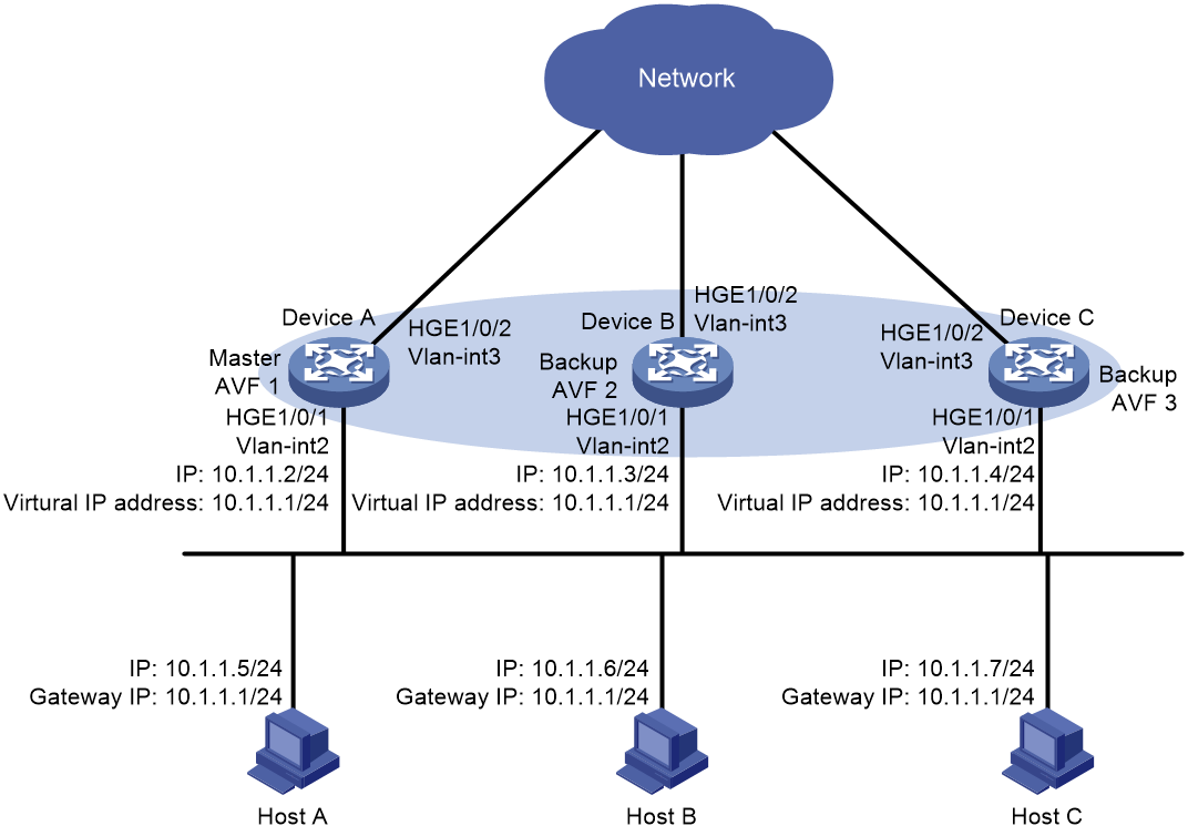
As shown in Figure 3, configure a load-balanced VRRP group on Device A, Device B, and Device C as the gateway for the hosts to meet the following requirements:
· Packets from the hosts are load balanced among the devices.
· If one device fails, hosts can access the external network through the other devices.
Analysis
To meet the network requirements, you must perform the following tasks:
· To avoid frequent role change in the VRRP group, set a preemption delay.
· For traffic to be switched to the other two devices when the uplink interface of one device fails, configure VF tracking on Device A, Device B, and Device C. When the uplink interface of one device fails, the weights of the VFs (including the AVF) on the device decrease by the specified value.
· For the failed device to become the master when it recovers, configure the preemptive mode for the VRRP group.
Software versions used
This configuration example was created and verified on R3606.
Restrictions and guidelines
When you configure VRRP load balancing, follow these restrictions and guidelines:
· The virtual IP address of a VRRP group cannot be any of the following addresses:
¡ All-zero address (0.0.0.0).
¡ Broadcast address (255.255.255.255).
¡ Loopback address.
¡ IP address of other than Class A, Class B, and Class C.
¡ Invalid IP address (for example, 0.0.0.1).
· For the hosts to access the external network, make sure the following IP addresses are on the same subnet:
¡ The virtual IP address of the VRRP group.
¡ The downlink interface IP addresses of the VRRP group members.
· IPv4 VRRP can use VRRPv2 or VRRPv3 (default version). For a VRRP group to operate correctly, make sure the VRRP versions on all devices in the VRRP group are the same.
· In load balancing mode, the virtual IP address of a VRRP group cannot be the IP address of any interface in the VRRP group. Otherwise, VRRP load balancing cannot operate correctly.
· If the uplink interface of the VF owner fails, an LVF must take over as the AVF. The switchover occurs when the weight of the VF owner drops below the lower limit of failure. This requires the reduced weight for the VF owner to be higher than 245.
· Configure the same virtual IP addresses for each device in the VRRP group.
· Make sure the decreased priority of the master is lower than the priority of all the other devices in the VRRP group. Another device in the group can then be elected as the master.
· By default, interfaces on the device are disabled (in ADM or Administratively Down state). To have an interface operate, you must use the undo shutdown command to enable that interface.
· The physical interfaces in this example must operate at Layer 2. By default, the interfaces on the device operate at Layer 3. You must use the port link-mode command to change the link mode of the interfaces to Layer 2.
Procedures
Configuring Device A
1. Configure the interfaces:
<DeviceA> system-view
[DeviceA] interface hundredgige 1/0/1
[DeviceA-HundredGigE1/0/1] undo shutdown
[DeviceA-HundredGigE1/0/1] quit
[DeviceA] vlan 2
[DeviceA-vlan2] port hundredgige 1/0/1
[DeviceA-vlan2] quit
[DeviceA] interface vlan-interface 2
[DeviceA-Vlan-interface2] ip address 10.1.1.2 24
[DeviceA-Vlan-interface2] quit
[DeviceA] interface hundredgige 1/0/2
[DeviceA-HundredGigE1/0/2] undo shutdown
[DeviceA-HundredGigE1/0/2] quit
[DeviceA] vlan 3
[DeviceA-vlan3] port hundredgige 1/0/2
[DeviceA-vlan3] quit
[DeviceA] interface vlan-interface 3
[DeviceA-Vlan-interface3] quit
2. Configure VRRP:
# Configure VRRP to operate in load balancing mode.
[DeviceA] vrrp mode load-balance
# Create VRRP group 1, and set its virtual IP address to 10.1.1.1.
[DeviceA] interface vlan-interface 2
[DeviceA-Vlan-interface2] vrrp vrid 1 virtual-ip 10.1.1.1
# Set the priority of Device A to 120 in VRRP group 1. Device A has the highest priority in VRRP group 1, so Device A can become the master.
[DeviceA-Vlan-interface2] vrrp vrid 1 priority 120
# Configure Device A to operate in preemptive mode, and set the preemption delay to 5 seconds.
[DeviceA-Vlan-interface2] vrrp vrid 1 preempt-mode delay 500
[DeviceA-Vlan-interface2] quit
3. Configure Track:
# Create track entry 1 to monitor the link status of the uplink interface HundredGigE 1/0/2. If the uplink interface fails, the track entry transits to Negative.
[DeviceA] track 1 interface hundredgige 1/0/2
[DeviceA-track-1] quit
# Configure the VFs in VRRP group 1 to monitor track entry 1, and decrease their weights by 250 when the track entry transits to Negative.
[DeviceA] interface vlan-interface 2
[DeviceA-Vlan-interface2] vrrp vrid 1 weight track 1 weight reduced 250
[DeviceA-Vlan-interface2] quit
Configuring Device B
1. Configure the interfaces:
<DeviceB> system-view
[DeviceB] interface hundredgige 1/0/1
[DeviceB-HundredGigE1/0/1] undo shutdown
[DeviceB-HundredGigE1/0/1] quit
[DeviceB] vlan 2
[DeviceB-vlan2] port hundredgige 1/0/1
[DeviceB-vlan2] quit
[DeviceB] interface vlan-interface 2
[DeviceB-Vlan-interface2] ip address 10.1.1.3 24
[DeviceB-Vlan-interface2] quit
[DeviceB] interface hundredgige 1/0/2
[DeviceB-HundredGigE1/0/2] undo shutdown
[DeviceB-HundredGigE1/0/2] quit
[DeviceB] vlan 3
[DeviceB-vlan3] port hundredgige 1/0/2
[DeviceB-vlan3] quit
[DeviceB] interface vlan-interface 3
[DeviceB-Vlan-interface3] quit
2. Configure VRRP:
# Configure VRRP to operate in load balancing mode.
[DeviceB] vrrp mode load-balance
# Create VRRP group 1, and set its virtual IP address to 10.1.1.1.
[DeviceB] interface vlan-interface 2
[DeviceB-Vlan-interface2] vrrp vrid 1 virtual-ip 10.1.1.1
# Set the priority of Device B to 110 in VRRP group 1. Device B has a higher priority than Device C in VRRP group 1, so Device B can become the master when Device A fails.
[DeviceB-Vlan-interface2] vrrp vrid 1 priority 110
# Configure Device B to operate in preemptive mode, and set the preemption delay to 5 seconds.
[DeviceB-Vlan-interface2] vrrp vrid 1 preempt-mode delay 500
[DeviceB-Vlan-interface2] quit
3. Configure Track:
# Create track entry 1 to monitor the link status of the uplink interface HundredGigE 1/0/2. When the uplink interface fails, the track entry transits to Negative.
[DeviceB] track 1 interface hundredgige 1/0/2
[DeviceB-track-1] quit
# Configure the VFs in VRRP group 1 to monitor track entry 1, and decrease their weights by 250 when the track entry transits to Negative.
[DeviceB] interface vlan-interface 2
[DeviceB-Vlan-interface2] vrrp vrid 1 weight track 1 weight reduced 250
[DeviceB-Vlan-interface2] quit
Configuring Device C
1. Configure the interfaces:
<DeviceC> system-view
[DeviceC] interface hundredgige 1/0/1
[DeviceC-HundredGigE1/0/1] undo shutdown
[DeviceC-HundredGigE1/0/1] quit
[DeviceC] vlan 2
[DeviceC-vlan2] port hundredgige 1/0/1
[DeviceC-vlan2] quit
[DeviceC] interface vlan-interface 2
[DeviceC-Vlan-interface2] ip address 10.1.1.4 24
[DeviceC-Vlan-interface2] quit
[DeviceC] interface hundredgige 1/0/2
[DeviceC-HundredGigE1/0/2] undo shutdown
[DeviceC-HundredGigE1/0/2] quit
[DeviceC] vlan 3
[DeviceC-vlan3] port hundredgige 1/0/2
[DeviceC-vlan3] quit
[DeviceC] interface vlan-interface 3
[DeviceC-Vlan-interface3] quit
2. Configure VRRP:
# Configure VRRP to operate in load balancing mode.
[DeviceC] vrrp mode load-balance
# Create VRRP group 1, and set its virtual IP address to 10.1.1.1.
[DeviceC] interface vlan-interface 2
[DeviceC-Vlan-interface2] vrrp vrid 1 virtual-ip 10.1.1.1
# Configure Device C to operate in preemptive mode, and set the preemption delay to 5 seconds.
[DeviceC-Vlan-interface2] vrrp vrid 1 preempt-mode delay 500
[DeviceC-Vlan-interface2] quit
3. Configure Track:
# Create track entry 1 to monitor the link status of the uplink interface HundredGigE 1/0/2. When the uplink interface fails, the track entry transits to Negative.
[DeviceC] track 1 interface hundredgige 1/0/2
[DeviceC-track-1] quit
# Configure the VFs in VRRP group 1 to monitor track entry 1, and decrease their weights by 250 when the track entry transits to Negative.
[DeviceC] interface vlan-interface 2
[DeviceC-Vlan-interface2] vrrp vrid 1 weight track 1 weight reduced 250
[DeviceC-Vlan-interface2] quit
Verifying the configuration
1. Verify that Host A can ping the external network. (Details not shown.)
2. Verify that Device A is operating as the master and Device B and Device C as the backups in VRRP group 1. Each of the three devices has one AVF and two LVFs.
# Display detailed information about VRRP group 1 on Device A.
[DeviceA] display vrrp verbose
IPv4 Virtual Device Information:
Running mode : Load balance
Total number of virtual routers : 1
Interface Vlan-interface2
VRID : 1 Adver Timer : 100 centiseconds
Admin Status : Up State : Master
Config Pri : 120 Running Pri : 120
Preempt Mode : Yes Delay Time : 500 centiseconds
Auth Type : None
Virtual IP : 10.1.1.1
Member IP List : 10.1.1.2 (Local, Master)
10.1.1.3 (Backup)
10.1.1.4 (Backup)
Forwarder Information: 3 Forwarders 1 Active
Config Weight : 255
Running Weight : 255
Forwarder 01
State : Active
Virtual MAC : 000f-e2ff-0011 (Owner)
Owner ID : 0000-5e01-1101
Priority : 255
Active : local
Forwarder 02
State : Listening
Virtual MAC : 000f-e2ff-0012 (Learnt)
Owner ID : 0000-5e01-1103
Priority : 127
Active : 10.1.1.3
Forwarder 03
State : Listening
Virtual MAC : 000f-e2ff-0013 (Learnt)
Owner ID : 0000-5e01-1105
Priority : 127
Active : 10.1.1.4
Forwarder Weight Track Information:
Track Object : 1 State : Positive Weight Reduced : 250
# Display detailed information about VRRP group 1 on Device B.
[DeviceB] display vrrp verbose
IPv4 Virtual Device Information:
Running mode : Load balance
Total number of virtual routers : 1
Interface Vlan-interface2
VRID : 1 Adver Timer : 100 centiseconds
Admin Status : Up State : Backup
Config Pri : 110 Running Pri : 110
Preempt Mode : Yes Delay Time : 500 centiseconds
Auth Type : None
Virtual IP : 10.1.1.1
Member IP List : 10.1.1.3 (Local, Backup)
10.1.1.2 (Master)
10.1.1.4 (Backup)
Forwarder Information: 3 Forwarders 1 Active
Config Weight : 255
Running Weight : 255
Forwarder 01
State : Listening
Virtual MAC : 000f-e2ff-0011 (Learnt)
Owner ID : 0000-5e01-1101
Priority : 127
Active : 10.1.1.2
Forwarder 02
State : Active
Virtual MAC : 000f-e2ff-0012 (Owner)
Owner ID : 0000-5e01-1103
Priority : 255
Active : local
Forwarder 03
State : Listening
Virtual MAC : 000f-e2ff-0013 (Learnt)
Owner ID : 0000-5e01-1105
Priority : 127
Active : 10.1.1.4
Forwarder Weight Track Information:
Track Object : 1 State : Positive Weight Reduced : 250
# Display detailed information about VRRP group 1 on Device C.
[DeviceC] display vrrp verbose
IPv4 Virtual Device Information:
Running mode : Load balance
Total number of virtual routers : 1
Interface Vlan-interface2
VRID : 1 Adver Timer : 100 centiseconds
Admin Status : Up State : Backup
Config Pri : 100 Running Pri : 100
Preempt Mode : Yes Delay Time : 500 centiseconds
Auth Type : None
Virtual IP : 10.1.1.1
Member IP List : 10.1.1.4 (Local, Backup)
10.1.1.2 (Master)
10.1.1.3 (Backup)
Forwarder Information: 3 Forwarders 1 Active
Config Weight : 255
Running Weight : 255
Forwarder 01
State : Listening
Virtual MAC : 000f-e2ff-0011 (Learnt)
Owner ID : 0000-5e01-1101
Priority : 127
Active : 10.1.1.2
Forwarder 02
State : Listening
Virtual MAC : 000f-e2ff-0012 (Learnt)
Owner ID : 0000-5e01-1103
Priority : 127
Active : 10.1.1.3
Forwarder 03
State : Active
Virtual MAC : 000f-e2ff-0013 (Owner)
Owner ID : 0000-5e01-1105
Priority : 255
Active : local
Forwarder Weight Track Information:
Track Object : 1 State : Positive Weight Reduced : 250
3. Verify that AVF switchover can be performed when the uplink interface of Device A fails.
# Display detailed information about VRRP group 1 on Device A.
[DeviceA] display vrrp verbose
IPv4 Virtual Device Information:
Running mode : Load balance
Total number of virtual routers : 1
Interface Vlan-interface2
VRID : 1 Adver Timer : 100 centiseconds
Admin Status : Up State : Master
Config Pri : 120 Running Pri : 120
Preempt Mode : Yes Delay Time : 500 centiseconds
Auth Type : None
Virtual IP : 10.1.1.1
Member IP List : 10.1.1.2 (Local, Master)
10.1.1.3 (Backup)
10.1.1.4 (Backup)
Forwarder Information: 3 Forwarders 0 Active
Config Weight : 255
Running Weight : 5
Forwarder 01
State : Initialize
Virtual MAC : 000f-e2ff-0011 (Owner)
Owner ID : 0000-5e01-1101
Priority : 0
Active : 10.1.1.4
Forwarder 02
State : Initialize
Virtual MAC : 000f-e2ff-0012 (Learnt)
Owner ID : 0000-5e01-1103
Priority : 0
Active : 10.1.1.3
Forwarder 03
State : Initialize
Virtual MAC : 000f-e2ff-0013 (Learnt)
Owner ID : 0000-5e01-1105
Priority : 0
Active : 10.1.1.4
Forwarder Weight Track Information:
Track Object : 1 State : Negative Weight Reduced : 250
# Display detailed information about VRRP group 1 on Device C.
[DeviceC] display vrrp verbose
IPv4 Virtual Device Information:
Running mode : Load balance
Total number of virtual routers : 1
Interface Vlan-interface2
VRID : 1 Adver Timer : 100 centiseconds
Admin Status : Up State : Backup
Config Pri : 100 Running Pri : 100
Preempt Mode : Yes Delay Time : 500 centiseconds
Auth Type : None
Become Master : 3550ms left
Virtual IP : 10.1.1.1
Member IP List : 10.1.1.4 (Local, Backup)
10.1.1.2 (Master)
10.1.1.3 (Backup)
Forwarder Information: 3 Forwarders 2 Active
Config Weight : 255
Running Weight : 255
Forwarder 01
State : Active
Virtual MAC : 000f-e2ff-0011 (Take Over)
Owner ID : 0000-5e01-1101
Priority : 85
Active : local
Redirect Time : 93 secs
Time-out Time : 1293 secs
Forwarder 02
State : Listening
Virtual MAC : 000f-e2ff-0012 (Learnt)
Owner ID : 0000-5e01-1103
Priority : 85
Active : 10.1.1.3
Forwarder 03
State : Active
Virtual MAC : 000f-e2ff-0013 (Owner)
Owner ID : 0000-5e01-1105
Priority : 255
Active : local
Forwarder Weight Track Information:
Track Object : 1 State : Positive Weight Reduced : 250
The output shows that when the uplink interface of Device A fails, the weights of the VFs on Device A drop below the lower limit of failure. All VFs on Device A transit to Initialized state and cannot forward traffic. The VF for MAC address 000f-e2ff-0011 on Device C becomes the AVF to forward traffic.
4. Verify that the VF for virtual MAC address 000f-e2ff-0011 is removed from Device C when the timeout timer (about 1800 seconds) expires. The VF no longer forwards the packets destined for the MAC address.
[DeviceC] display vrrp verbose
IPv4 Virtual Device Information:
Running mode : Load balance
Total number of virtual routers : 1
Interface Vlan-interface2
VRID : 1 Adver Timer : 100 centiseconds
Admin Status : Up State : Backup
Config Pri : 100 Running Pri : 100
Preempt Mode : Yes Delay Time : 500 centiseconds
Auth Type : None
Become Master : 3550ms left
Virtual IP : 10.1.1.1
Member IP List : 10.1.1.4 (Local, Backup)
10.1.1.2 (Master)
10.1.1.3 (Backup)
Forwarder Information: 2 Forwarders 1 Active
Config Weight : 255
Running Weight : 255
Forwarder 02
State : Listening
Virtual MAC : 000f-e2ff-0012 (Learnt)
Owner ID : 0000-5e01-1103
Priority : 127
Active : 10.1.1.3
Forwarder 03
State : Active
Virtual MAC : 000f-e2ff-0013 (Owner)
Owner ID : 0000-5e01-1105
Priority : 255
Active : local
Forwarder Weight Track Information:
Track Object : 1 State : Positive Weight Reduced : 250
5. Verify that Device B has a higher priority than Device C and becomes the master when Device A fails.
[DeviceB] display vrrp verbose
IPv4 Standby Information:
Run mode : Load balance
Run Method : Virtual MAC
Total number of virtual routers : 1
Interface Vlan-interface2
VRID : 1 Adver Timer : 1 centiseconds
Admin Status : Up State : Master
Config Pri : 110 Running Pri : 110
Preempt Mode : Yes Delay Time : 500 centiseconds
Auth Type : None
Virtual IP : 10.1.1.1
Member IP List : 10.1.1.3 (Local, Master)
10.1.1.4 (Backup)
Forwarder Information: 2 Forwarders 1 Active
Config Weight : 255
Running Weight : 255
Forwarder 02
State : Active
Virtual MAC : 000f-e2ff-0012 (Owner)
Owner ID : 0000-5e01-1103
Priority : 255
Active : local
Forwarder 03
State : Listening
Virtual MAC : 000f-e2ff-0013 (Learnt)
Owner ID : 0000-5e01-1105
Priority : 127
Active : 10.1.1.4
Forwarder Weight Track Information:
Track Object : 1 State : Positive Weight Reduced : 250
Configuration files
· Device A:
#
vrrp mode load-balance
#
vlan 2 to 3
#
interface Vlan-interface2
ip address 10.1.1.2 255.255.255.0
vrrp vrid 1 virtual-ip 10.1.1.1
vrrp vrid 1 priority 120
vrrp vrid 1 preempt-mode delay 500
vrrp vrid 1 weight track 1 weight reduced 250
#
interface Vlan-interface3
#
interface HundredGigE1/0/1
port link-mode bridge
port access vlan 2
#
interface HundredGigE1/0/2
port link-mode bridge
port access vlan 3
#
track 1 interface HundredGigE1/0/2
#
· Device B:
#
vrrp mode load-balance
#
vlan 2 to 3
#
interface Vlan-interface2
ip address 10.1.1.3 255.255.255.0
vrrp vrid 1 virtual-ip 10.1.1.1
vrrp vrid 1 priority 110
vrrp vrid 1 preempt-mode delay 500
vrrp vrid 1 weight track 1 weight reduced 250
#
interface Vlan-interface3
#
interface HundredGigE1/0/1
port link-mode bridge
port access vlan 2
#
interface HundredGigE1/0/2
port link-mode bridge
port access vlan 3
#
track 1 interface HundredGigE1/0/2
#
· Device C:
#
vrrp mode load-balance
#
vlan 2 to 3
#
interface Vlan-interface2
ip address 10.1.1.4 255.255.255.0
vrrp vrid 1 virtual-ip 10.1.1.1
vrrp vrid 1 preempt-mode delay 500
vrrp vrid 1 weight track 1 weight reduced 250
#
interface Vlan-interface3
#
interface HundredGigE1/0/1
port link-mode bridge
port access vlan 2
#
interface HundredGigE1/0/2
port link-mode bridge
port access vlan 3
#
track 1 interface HundredGigE1/0/2
#
Example: Configuring a single IPv6 VRRP group
Network configuration
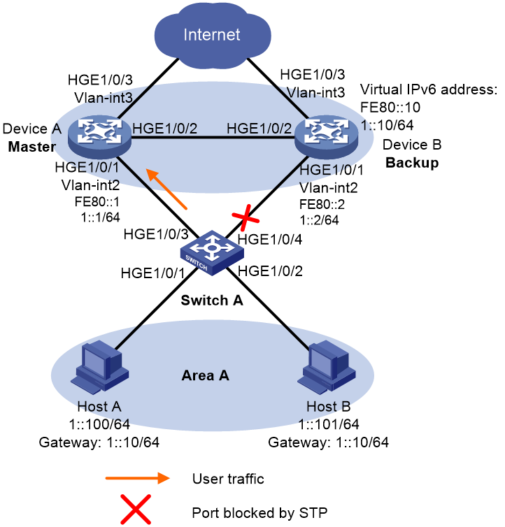
As shown in Figure 4, configure an IPv6 VRRP group on Device A and Device B as the gateway for hosts in Area A to meet the following requirements:
· Device A operates as the master to forward packets from the hosts in Area A to the external network.
· If Device A or its uplink interface fails, the hosts in Area A can access the external network through Device B.
Analysis
To meet the network requirements, you must perform the following tasks:
· For Device A to become the master when it recovers from a failure, configure the preemptive mode for the VRRP group.
· For Device A to decrease its priority and become a backup when its uplink interface fails, configure VRRP tracking on Device A.
· To avoid frequent role change in the VRRP group, set a preemption delay.
· To avoid loops between Device A, Device B, and the Layer 2 switches, use the spanning tree feature to block a port in the IPv6 VRRP group.
Software versions used
This configuration example was created and verified on R3606.
Restrictions and guidelines
When you configure a single IPv6 VRRP group, follow these restrictions and guidelines:
· For the hosts in Area A to access the external network, make sure the following IP addresses are on the same subnet:
¡ The virtual IPv6 address of the VRRP group.
¡ The downlink interface IPv6 addresses of the VRRP group members.
· IPv6 VRRP can use VRRPv2 or VRRPv3 (default version). For an IPv6 VRRP group to operate correctly, make sure the VRRP versions on all devices in the VRRP group are the same.
· Removal of the IPv6 VRRP group on the IP address owner causes IP address collision. To avoid a collision, change the IP address of the interface on the IP address owner before you remove the VRRP group from the interface.
· Configure the same virtual IPv6 addresses for each device in the IPv6 VRRP group.
· Make sure the decreased priority of the master is lower than the priority of all the other devices in the IPv6 VRRP group. Another device in the group can then be elected as the master.
· By default, interfaces on the device are disabled (in ADM or Administratively Down state). To have an interface operate, you must use the undo shutdown command to enable that interface.
· The physical interfaces in this example must operate at Layer 2. By default, the interfaces on the device operate at Layer 3. You must use the port link-mode command to change the link mode of the interfaces to Layer 2.
Procedures
Configuring Device A
# Create VLAN 2 and assign HundredGigE 1/0/1 to VLAN 2.
<DeviceA> system-view
[DeviceA] interface hundredgige 1/0/1
[DeviceA-HundredGigE1/0/1] undo shutdown
[DeviceA-HundredGigE1/0/1] quit
[DeviceA] vlan 2
[DeviceA-vlan2] port hundredgige 1/0/1
[DeviceA-vlan2] quit
# Create VLAN-interface 2 and assign IPv6 addresses to the VLAN interface.
[DeviceA] interface vlan-interface 2
[DeviceA-Vlan-interface2] ipv6 address fe80::1 link-local
[DeviceA-Vlan-interface2] ipv6 address 1::1 64
# Create IPv6 VRRP group 1, and set its virtual IPv6 addresses to FE80::10 and 1::10.
[DeviceA-Vlan-interface2] vrrp ipv6 vrid 1 virtual-ip fe80::10 link-local
[DeviceA-Vlan-interface2] vrrp ipv6 vrid 1 virtual-ip 1::10
# Disable RA message suppression on VLAN-interface 2. The hosts in Area A can learn the default gateway address from the RA messages.
[DeviceA-Vlan-interface2] undo ipv6 nd ra halt
# Set the priority of Device A to 110 in IPv6 VRRP group 1. Device A has a higher priority than Device B in IPv6 VRRP group 1, so Device A can become the master.
[DeviceA-Vlan-interface2] vrrp ipv6 vrid 1 priority 110
# Configure Device A to operate in preemptive mode, and set the preemption delay to 5 seconds.
[DeviceA-Vlan-interface2] vrrp ipv6 vrid 1 preempt-mode delay 500
[DeviceA-Vlan-interface2] quit
# Create track entry 1 to monitor the link status of the uplink interface HundredGigE 1/0/3.
[DeviceA] track 1 interface hundredgige 1/0/3
[DeviceA-track-1] quit
# Associate IPv6 VRRP group 1 with track entry 1 and decrease the device priority by 50 when the state of track entry 1 changes to Negative.
[DeviceA] interface vlan-interface 2
[DeviceA-Vlan-interface2] vrrp ipv6 vrid 1 track 1 priority reduced 50
[DeviceA-Vlan-interface2] quit
# Configure HundredGigE 1/0/2 as a trunk port, and assign the port to VLAN 2.
[DeviceA] interface hundredgige 1/0/2
[DeviceA-HundredGigE1/0/2] port link-mode bridge
[DeviceA-HundredGigE1/0/2] port link-type trunk
[DeviceA-HundredGigE1/0/2] undo port trunk permit vlan 1
[DeviceA-HundredGigE1/0/2] port trunk permit vlan 2
[DeviceA-HundredGigE1/0/2] port trunk pvid vlan 2
[DeviceA-HundredGigE1/0/2] quit
# Configure MSTP, map VLAN 2 to MSTI 1, and configure Device A as the root bridge of MSTI 1.
[DeviceA] stp region-configuration
[DeviceA-mst-region] region-name vrrp
[DeviceA-mst-region] instance 1 vlan 2
[DeviceA-mst-region] active region-configuration
[DeviceA-mst-region] quit
[DeviceA] stp instance 1 root primary
# Enable the spanning tree feature globally.
[DeviceA] stp global enable
Configuring Device B
# Create VLAN 2 and assign HundredGigE 1/0/1 to VLAN 2.
<DeviceB> system-view
[DeviceB] interface hundredgige 1/0/1
[DeviceB-HundredGigE1/0/1] undo shutdown
[DeviceB-HundredGigE1/0/1] quit
[DeviceB] vlan 2
[DeviceB-vlan2] port hundredgige 1/0/1
[DeviceB-vlan2] quit
# Create VLAN-interface 2 and assign IPv6 addresses to the VLAN interface.
[DeviceB] interface vlan-interface 2
[DeviceB-Vlan-interface2] ipv6 address fe80::2 link-local
[DeviceB-Vlan-interface2] ipv6 address 1::2 64
# Create IPv6 VRRP group 1, and set its virtual IPv6 addresses to FE80::10 and 1::10.
[DeviceB-Vlan-interface2] vrrp ipv6 vrid 1 virtual-ip fe80::10 link-local
[DeviceB-Vlan-interface2] vrrp ipv6 vrid 1 virtual-ip 1::10
# Disable RA message suppression on VLAN-interface 2. The hosts in Area A can learn the default gateway address from the RA messages.
[DeviceB-Vlan-interface2] undo ipv6 nd ra halt
# Configure Device B to operate in preemptive mode, and set the preemption delay to 5 seconds.
[DeviceB-Vlan-interface2] vrrp ipv6 vrid 1 preempt-mode delay 500
[DeviceB-Vlan-interface2] quit
# Configure HundredGigE 1/0/2 as a trunk port, and assign the port to VLAN 2.
[DeviceB] interface hundredgige 1/0/2
[DeviceB-HundredGigE1/0/2] port link-mode bridge
[DeviceB-HundredGigE1/0/2] port link-type trunk
[DeviceB-HundredGigE1/0/2] undo port trunk permit vlan 1
[DeviceB-HundredGigE1/0/2] port trunk permit vlan 2
[DeviceB-HundredGigE1/0/2] port trunk pvid vlan 2
[DeviceB-HundredGigE1/0/2] quit
# Configure MSTP, map VLAN 2 to MSTI 1, and configure Device B as a secondary root bridge in MSTI 1.
[DeviceB] stp region-configuration
[DeviceB-mst-region] region-name vrrp
[DeviceB-mst-region] instance 1 vlan 2
[DeviceB-mst-region] active region-configuration
[DeviceB-mst-region] quit
[DeviceB] stp instance 1 root secondary
# Enable the spanning tree feature globally.
[DeviceB] stp global enable
Configuring Switch A
# Set the MST region name of the device to vrrp.
<SwitchA> system-view
[SwitchA] stp region-configuration
[SwitchA-mst-region] region-name vrrp
# Map VLAN 2 to MSTI 1 and activate the MST region configuration.
[SwitchA-mst-region] instance 1 vlan 2
[SwitchA-mst-region] active region-configuration
[SwitchA-mst-region] quit
# Enable the spanning tree feature globally.
[SwitchA] stp global enable
Verifying the configuration
1. Verify that Host A in Area A can ping the IPv6 address 30::1.
Microsoft Windows [Version 6.1.7601]
Copyright (c) 2009 Microsoft Corporation. All rights reserved.
C:\Users\hostA>ping 30::1
Pinging 30::1 with 32 bytes of data:
Reply from 30::1: time<1ms
Reply from 30::1: time<1ms
Reply from 30::1: time<1ms
Reply from 30::1: time<1ms
Ping statistics for 30::1:
Packets: Sent = 4, Received = 4, Lost = 0 (0% loss),
Approximate round trip times in milli-seconds:
Minimum = 0ms, Maximum = 0ms, Average = 0ms
2. Verify that Device A is operating as the master and Device B as the backup in IPv6 VRRP group 1. Device A forwards packets from the hosts in Area A to the external network.
# Display detailed information about IPv6 VRRP group 1 on Device A.
[DeviceA] display vrrp ipv6 verbose
IPv6 Virtual Router Information:
Running mode : Standard
Total number of virtual routers : 1
Interface Vlan-interface2
VRID : 1 Adver Timer : 100 centiseconds
Admin Status : Up State : Master
Config Pri : 110 Running Pri : 110
Preempt Mode : Yes Delay Time : 500 centiseconds
Auth Type : None
Virtual IP : FE80::10
1::10
Virtual MAC : 0000-5e00-0201
Master IP : FE80::1
VRRP Track Information:
Track Object : 1 State : Positive Pri Reduced : 50
# Display detailed information about IPv6 VRRP group 1 on Device B.
[DeviceB] display vrrp ipv6 verbose
IPv6 Virtual Router Information:
Running mode : Standard
Total number of virtual routers : 1
Interface Vlan-interface2
VRID : 1 Adver Timer : 100 centiseconds
Admin Status : Up State : Backup
Config Pri : 100 Running Pri : 100
Preempt Mode : Yes Delay Time : 500 centiseconds
Become Master : 3000ms left
Auth Type : None
Virtual IP : FE80::10
1::10
Virtual MAC : 0000-5e00-0201
Master IP : FE80::1
3. Verify that Host A can still ping the IPv6 address 30::1 after Device A or its uplink interface fails.
Microsoft Windows [Version 6.1.7601]
Copyright (c) 2009 Microsoft Corporation. All rights reserved.
C:\Users\hostA>ping 30::1
Pinging 30::1 with 32 bytes of data:
Reply from 30::1: time<1ms
Reply from 30::1: time<1ms
Reply from 30::1: time<1ms
Reply from 30::1: time<1ms
Ping statistics for 30::1:
Packets: Sent = 4, Received = 4, Lost = 0 (0% loss),
Approximate round trip times in milli-seconds:
Minimum = 0ms, Maximum = 0ms, Average = 0ms
4. Verify that Device B takes over to forward packets from the hosts in Area A to the external network after Device A or its uplink interface fails.
[DeviceB] display vrrp ipv6 verbose
IPv6 Virtual Router Information:
Running mode : Standard
Total number of virtual routers : 1
Interface Vlan-interface2
VRID : 1 Adver Timer : 100 centiseconds
Admin Status : Up State : Master
Config Pri : 100 Running Pri : 100
Preempt Mode : Yes Delay Time : 500 centiseconds
Auth Type : None
Virtual IP : FE80::10
1::10
Virtual MAC : 0000-5e00-0201
Master IP : FE80::2
5. Verify that Device A becomes the master to forward packets from the hosts in Area A to the external network when Device A or its uplink interface recovers.
[DeviceA] display vrrp ipv6 verbose
IPv6 Virtual Router Information:
Running mode : Standard
Total number of virtual routers : 1
Interface Vlan-interface2
VRID : 1 Adver Timer : 100 centiseconds
Admin Status : Up State : Master
Config Pri : 110 Running Pri : 110
Preempt Mode : Yes Delay Time : 500 centiseconds
Auth Type : None
Virtual IP : FE80::10
1::10
Virtual MAC : 0000-5e00-0201
Master IP : FE80::1
VRRP Track Information:
Track Object : 1 State : Positive Pri Reduced : 50
Configuration files
· Device A:
#
sysname DeviceA
#
stp region-configuration
region-name vrrp
instance 1 vlan 2
active region-configuration
#
stp instance 1 root primary
stp global enable
#
interface Vlan-interface2
ipv6 address fe80::1 link-local
ipv6 address 1::1/64
undo ipv6 nd ra halt
vrrp ipv6 vrid 1 virtual-ip FE80::10 link-local
vrrp ipv6 vrid 1 virtual-ip 1::10
vrrp ipv6 vrid 1 priority 110
vrrp ipv6 vrid 1 preempt-mode delay 500
vrrp ipv6 vrid 1 track 1 priority reduced 50
#
interface HundredGigE1/0/1
port link-mode bridge
port access vlan 2
#
interface HundredGigE1/0/2
port link-mode bridge
port link-type trunk
undo port trunk permit vlan 1
port trunk permit vlan 2
port trunk pvid vlan 2
#
track 1 interface HundredGigE1/0/3
#
· Device B:
#
sysname DeviceB
#
stp region-configuration
region-name vrrp
instance 1 vlan 2
active region-configuration
#
stp instance 1 root secondary
stp global enable
#
interface Vlan-interface2
ipv6 address fe80::2 link-local
ipv6 address 1::2/64
undo ipv6 nd ra halt
vrrp ipv6 vrid 1 virtual-ip FE80::10 link-local
vrrp ipv6 vrid 1 virtual-ip 1::10
vrrp ipv6 vrid 1 preempt-mode delay 500
#
interface HundredGigE1/0/1
port link-mode bridge
port access vlan 2
#
interface HundredGigE1/0/2
port link-mode bridge
port link-type trunk
undo port trunk permit vlan 1
port trunk permit vlan 2
port trunk pvid vlan 2
#
· Switch A:
#
sysname SwitchA
#
stp region-configuration
region-name vrrp
instance 1 vlan 2
active region-configuration
#
stp global enable
#
Example: Configuring multiple IPv6 VRRP groups
Network configuration
As shown in Figure 5, configure two IPv6 VRRP groups on Device A and Device B as gateways for internal hosts to meet the following requirements:
· Device A operates as the master of IPv6 VRRP group 1 to forward packets from Area A. Device B operates as the master of IPv6 VRRP group 2 to forward packets from Area B.
· When one device or its uplink interface fails, the other device provides gateway service for both areas.
Analysis
To meet the network requirements, you must perform the following tasks:
· To avoid frequent role change in the VRRP group, set a preemption delay.
· For Device A or Device B to decrease its priority and become a backup in an IPv6 VRRP group when the uplink interface of the device fails, configure VRRP tracking on both devices.
· To avoid loops between Device A, Device B, and the Layer 2 switches, use the spanning tree feature to block a port in each IPv6 VRRP group.
Software versions used
This configuration example was created and verified on R3606.
Restrictions and guidelines
When you configure multiple IPv6 VRRP groups, follow these restrictions and guidelines:
· For the hosts in both areas to access the external network, make sure the following IP addresses for each VRRP group are on the same subnet:
¡ The virtual IPv6 address of the VRRP group.
¡ The downlink interface IPv6 addresses of the VRRP group members.
· IPv6 VRRP can use VRRPv2 or VRRPv3 (default version). For an IPv6 VRRP group to operate correctly, make sure the VRRP versions on all devices in the VRRP group are the same.
· Removal of the IPv6 VRRP group on the IP address owner causes IP address collision. To avoid a collision, change the IPv6 address of the interface on the IP address owner before you remove the VRRP group from the interface.
· Make sure the decreased priority of the master is lower than the priority of all the other devices in the VRRP group. Another device in the group can then be elected as the master.
· Make sure the following configurations are the same on the members of an IPv6 VRRP group:
¡ Number of virtual IPv6 addresses.
¡ Virtual IPv6 addresses.
¡ Advertisement interval.
· By default, interfaces on the device are disabled (in ADM or Administratively Down state). To have an interface operate, you must use the undo shutdown command to enable that interface.
· The physical interfaces in this example must operate at Layer 2. By default, the interfaces on the device operate at Layer 3. You must use the port link-mode command to change the link mode of the interfaces to Layer 2.
Procedures
Configuring Device A
# Create VLAN 101 and assign HundredGigE 1/0/1 to VLAN 101.
<DeviceA> system-view
[DeviceA] interface hundredgige 1/0/1
[DeviceA-HundredGigE1/0/1] undo shutdown
[DeviceA-HundredGigE1/0/1] quit
[DeviceA] vlan 101
[DeviceA-vlan101] port hundredgige 1/0/1
[DeviceA-vlan101] quit
# Create VLAN-interface 101, and assign IPv6 addresses to VLAN-interface 101.
[DeviceA] interface vlan-interface 101
[DeviceA-Vlan-interface101] ipv6 address fe80::1 link-local
[DeviceA-Vlan-interface101] ipv6 address 10::2 64
[DeviceA-Vlan-interface101] quit
# Assign IPv6 addresses to other VLAN interfaces of Device A. (Details not shown.)
# Configure HundredGigE 1/0/24 as a trunk port and assign the port to VLAN 101 and VLAN 102.
[DeviceA] interface hundredgige 1/0/24
[DeviceA-HundredGigE1/0/24] port link-mode bridge
[DeviceA-HundredGigE1/0/24] port link-type trunk
[DeviceA-HundredGigE1/0/24] undo port trunk permit vlan 1
[DeviceA-HundredGigE1/0/24] port trunk permit vlan 101 to 102
[DeviceA-HundredGigE1/0/24] port trunk pvid vlan 101
[DeviceA-HundredGigE1/0/24] quit
# Disable the spanning tree feature on HundredGigE 1/0/2.
[DeviceA] interface hundredgige 1/0/2
[DeviceA-HundredGigE1/0/2] port link-mode bridge
[DeviceA-HundredGigE1/0/2] undo stp enable
[DeviceA-HundredGigE1/0/2] quit
# Create IPv6 VRRP group 1, and set its virtual IPv6 addresses to FE80::10 and 10::1.
[DeviceA] interface vlan-interface 101
[DeviceA-Vlan-interface101] vrrp ipv6 vrid 1 virtual-ip fe80::10 link-local
[DeviceA-Vlan-interface101] vrrp ipv6 vrid 1 virtual-ip 10::1
# Configure Device A to operate in preemptive mode, and set the preemption delay to 5 seconds.
[DeviceA-Vlan-interface101] vrrp ipv6 vrid 1 preempt-mode delay 500
# Set the priority of Device A to 120 in IPv6 VRRP group 1. Device A has a higher priority than Device B in IPv6 VRRP group 1, so Device A can become the master.
[DeviceA-Vlan-interface101] vrrp ipv6 vrid 1 priority 120
# Disable RA message suppression on VLAN-interface 101. The hosts in Area A can learn the default gateway address from the RA messages.
[DeviceA-Vlan-interface101] undo ipv6 nd ra halt
[DeviceA-Vlan-interface101] quit
# Create IPv6 VRRP group 2, and set its virtual IPv6 addresses to FE80::20 and 11::1.
[DeviceA] interface vlan-interface 102
[DeviceA-Vlan-interface102] vrrp ipv6 vrid 2 virtual-ip fe80::20 link-local
[DeviceA-Vlan-interface102] vrrp ipv6 vrid 2 virtual-ip 11::1
# Configure Device A to operate in preemptive mode, and set the preemption delay to 5 seconds.
[DeviceA-Vlan-interface102] vrrp ipv6 vrid 2 preempt-mode delay 500
# Disable RA message suppression on VLAN-interface 102. The hosts in Area B can learn the default gateway address from the RA messages.
[DeviceA-Vlan-interface102] undo ipv6 nd ra halt
[DeviceA-Vlan-interface102] quit
# Create track entry 1 to monitor the link status of the uplink interface HundredGigE 1/0/2.
[DeviceA] track 1 interface hundredgige 1/0/2
[DeviceA-track-1] quit
# Associate IPv6 VRRP group 1 with track entry 1 and decrease the device priority by 50 when the state of track entry 1 changes to Negative.
[DeviceA] interface vlan-interface 101
[DeviceA-Vlan-interface101] vrrp ipv6 vrid 1 track 1 priority reduced 50
[DeviceA-Vlan-interface101] quit
# Configure MSTP, map VLAN 101 to MSTI 1 and VLAN 102 to MSTI 2, and configure Device A as the root bridge of MSTI 1.
[DeviceA] stp region-configuration
[DeviceA-mst-region] region-name vrrp
[DeviceA-mst-region] instance 1 vlan 101
[DeviceA-mst-region] instance 2 vlan 102
[DeviceA-mst-region] active region-configuration
[DeviceA-mst-region] quit
[DeviceA] stp instance 1 root primary
[DeviceA] stp instance 2 root secondary
# Enable the spanning tree feature globally.
[DeviceA] stp global enable
Configuring Device B
# Create VLAN 101, and assign HundredGigE 1/0/1 to VLAN 101.
<DeviceB> system-view
[DeviceB] interface hundredgige 1/0/1
[DeviceB-HundredGigE1/0/1] undo shutdown
[DeviceB-HundredGigE1/0/1] quit
[DeviceB] vlan 101
[DeviceB-vlan101] port hundredgige 1/0/1
[DeviceB-vlan101] quit
# Create VLAN-interface 101, and assign IPv6 addresses to VLAN-interface 101.
[DeviceB] interface vlan-interface 101
[DeviceB-Vlan-interface101] ipv6 address fe80::2 link-local
[DeviceB-Vlan-interface101] ipv6 address 10::3 64
[DeviceB-Vlan-interface101] quit
# Assign IPv6 addresses to other VLAN interfaces of Device B. (Details not shown.)
# Configure HundredGigE 1/0/24 as a trunk port, and assign the port to VLAN 101 and VLAN 102.
[DeviceB] interface hundredgige 1/0/24
[DeviceB-HundredGigE1/0/24] port link-mode bridge
[DeviceB-HundredGigE1/0/24] port link-type trunk
[DeviceB-HundredGigE1/0/24] undo port trunk permit vlan 1
[DeviceB-HundredGigE1/0/24] port trunk permit vlan 101 to 102
[DeviceB-HundredGigE1/0/24] port trunk pvid vlan 101
[DeviceB-HundredGigE1/0/24] quit
# Disable the spanning tree feature on HundredGigE 1/0/2.
[DeviceB] interface hundredgige 1/0/2
[DeviceB-HundredGigE1/0/2] port link-mode bridge
[DeviceB-HundredGigE1/0/2] undo stp enable
[DeviceB-HundredGigE1/0/2] quit
# Create IPv6 VRRP group 1, and set its virtual IPv6 addresses to FE80::10 and 10::1.
[DeviceB] interface vlan-interface 101
[DeviceB-Vlan-interface101] vrrp ipv6 vrid 1 virtual-ip fe80::10 link-local
[DeviceB-Vlan-interface101] vrrp ipv6 vrid 1 virtual-ip 10::1
# Configure Device B to operate in preemptive mode, and set the preemption delay to 5 seconds.
[DeviceB-Vlan-interface101] vrrp ipv6 vrid 1 preempt-mode delay 500
# Disable RA message suppression on VLAN-interface 101. The hosts in Area A can learn the default gateway address from the RA messages.
[DeviceB-Vlan-interface101] undo ipv6 nd ra halt
[DeviceB-Vlan-interface101] quit
# Create IPv6 VRRP group 2, and set its virtual IPv6 addresses to FE80::20 and 11::1.
[DeviceB] interface vlan-interface 102
[DeviceB-Vlan-interface102] vrrp ipv6 vrid 2 virtual-ip fe80::20 link-local
[DeviceB-Vlan-interface102] vrrp ipv6 vrid 2 virtual-ip 11::1
# Set the priority of Device B to 120 in IPv6 VRRP group 2. Device B has a higher priority than Device A in IPv6 VRRP group 2, so Device B can become the master.
[DeviceB-Vlan-interface102] vrrp ipv6 vrid 2 priority 120
# Configure Device B to operate in preemptive mode, and set the preemption delay to 5 seconds.
[DeviceA-Vlan-interface102] vrrp ipv6 vrid 2 preempt-mode delay 500
# Disable RA message suppression on VLAN-interface 102. The hosts in Area B can learn the default gateway address from the RA messages.
[DeviceB-Vlan-interface102] undo ipv6 nd ra halt
[DeviceB-Vlan-interface102] quit
# Create track entry 2 to monitor the link status of the uplink interface HundredGigE 1/0/2.
[DeviceB] track 2 interface hundredgige 1/0/2
[DeviceB-track-2] quit
# Associate IPv6 VRRP group 2 with track entry 2 and decrease the device priority by 50 when the state of track entry 2 changes to Negative.
[DeviceB] interface vlan-interface 102
[DeviceB-Vlan-interface102] vrrp ipv6 vrid 2 track 2 priority reduced 50
[DeviceB-Vlan-interface102] quit
# Configure MSTP, map VLAN 101 to MSTI 1 and VLAN 102 to MSTI 2, and configure Device B as the root bridge of MSTI 2.
[DeviceB] stp region-configuration
[DeviceB-mst-region] region-name vrrp
[DeviceB-mst-region] instance 1 vlan 101
[DeviceB-mst-region] instance 2 vlan 102
[DeviceB-mst-region] active region-configuration
[DeviceB-mst-region] quit
[DeviceB] stp instance 2 root primary
[DeviceB] stp instance 1 root secondary
# Enable the spanning tree feature globally.
[DeviceB] stp global enable
Configuring L2SwitchA
# Set the MST region name of the device to vrrp.
<L2SwitchA> system-view
[L2SwitchA] stp region-configuration
[L2SwitchA-mst-region] region-name vrrp
# Map VLAN 101 to MSTI 1, and activate the MST region configuration.
[L2SwitchA-mst-region] instance 1 vlan 101
[L2SwitchA-mst-region] active region-configuration
[L2SwitchA-mst-region] quit
# Enable the spanning tree feature globally.
[L2SwitchA] stp global enable
Configuring L2SwitchB
# Set the MST region name of the device to vrrp.
<L2SwitchB> system-view
[L2SwitchB] stp region-configuration
[L2SwitchB-mst-region] region-name vrrp
# Map VLAN 102 to MSTI 1, and activate the MST region configuration.
[L2SwitchB-mst-region] instance 1 vlan 102
[L2SwitchB-mst-region] active region-configuration
[L2SwitchB-mst-region] quit
# Enable the spanning tree feature globally.
[L2SwitchB] stp global enable
Verifying the configuration
1. Verify that the hosts in both Area A and Area B can ping the external network.
# Ping the IPv6 address 30::1 from a host in Area A.
Microsoft Windows [Version 6.1.7601]
Copyright (c) 2009 Microsoft Corporation. All rights reserved.
C:\Users\areaA>ping 30::1
Pinging 30::1 with 32 bytes of data:
Reply from 30::1: time<1ms
Reply from 30::1: time<1ms
Reply from 30::1: time<1ms
Reply from 30::1: time<1ms
Ping statistics for 30::1:
Packets: Sent = 4, Received = 4, Lost = 0 (0% loss),
Approximate round trip times in milli-seconds:
Minimum = 0ms, Maximum = 0ms, Average = 0ms
# Ping the IPv6 address 30::1 from a host in Area B.
Microsoft Windows [Version 6.1.7601]
Copyright (c) 2009 Microsoft Corporation. All rights reserved.
C:\Users\areaB>ping 30::1
Pinging 30::1 with 32 bytes of data:
Reply from 30::1: time<1ms
Reply from 30::1: time<1ms
Reply from 30::1: time<1ms
Reply from 30::1: time<1ms
Ping statistics for 30::1:
Packets: Sent = 4, Received = 4, Lost = 0 (0% loss),
Approximate round trip times in milli-seconds:
Minimum = 0ms, Maximum = 0ms, Average = 0ms
2. Verify that Device A is operating as the master in IPv6 VRRP group 1 and the backup in IPv6 VRRP group 2. Device B is operating as the master in IPv6 VRRP group 2 and the backup in IPv6 VRRP group 1.
# Display detailed information about all IPv6 VRRP groups on Device A.
[DeviceA] display vrrp ipv6 verbose
IPv6 Virtual Router Information:
Running mode : Standard
Total number of virtual routers : 2
Interface Vlan-interface101
VRID : 1 Adver Timer : 100 centiseconds
Admin Status : Up State : Master
Config Pri : 120 Running Pri : 120
Preempt Mode : Yes Delay Time : 500 centiseconds
Auth Type : None
Virtual IP : FE80::10
10::1
Virtual MAC : 0000-5e00-0201
Master IP : FE80::1
VRRP Track Information:
Track Object : 1 State : Positive Pri Reduced : 50
Interface Vlan-interface102
VRID : 2 Adver Timer : 100 centiseconds
Admin Status : Up State : Backup
Config Pri : 100 Running Pri : 100
Preempt Mode : Yes Delay Time : 500 centiseconds
Auth Type : None
Become Master : 3550ms left
Virtual MAC : 0000-5e00-0201
Virtual IP : FE80::20
11::1
Master IP : FE80::4
# Display detailed information about all IPv6 VRRP groups on Device B.
[DeviceB] display vrrp ipv6 verbose
IPv6 Virtual Router Information:
Running mode : Standard
Total number of virtual routers : 2
Interface Vlan-interface101
VRID : 1 Adver Timer : 100 centiseconds
Admin Status : Up State : Backup
Config Pri : 100 Running Pri : 100
Preempt Mode : Yes Delay Time : 500 centiseconds
Auth Type : None
Become Master : 3500ms left
Virtual IP : FE80::10
10::2
Virtual MAC : 0000-5e00-0202
Master IP : FE80::1
Interface Vlan-interface102
VRID : 2 Adver Timer : 100 centiseconds
Admin Status : Up State : Master
Config Pri : 120 Running Pri : 120
Preempt Mode : Yes Delay Time : 500 centiseconds
Auth Type : None
Virtual IP : FE80::20
11::1
Virtual MAC : 0000-5e00-0202
Master IP : FE80::4
VRRP Track Information:
Track Object : 2 State : Positive Pri Reduced : 50
3. Verify that Device B becomes the master in IPv6 VRRP group 1 when Device A or its uplink interface fails.
[DeviceB] display vrrp ipv6 verbose
IPv6 Virtual Router Information:
Running mode : Standard
Total number of virtual routers : 2
Interface Vlan-interface101
VRID : 1 Adver Timer : 100 centiseconds
Admin Status : Up State : Master
Config Pri : 100 Running Pri : 100
Preempt Mode : Yes Delay Time : 500 centiseconds
Auth Type : None
Virtual IP : FE80::10
10::2
Virtual MAC : 0000-5e00-0101
Master IP : FE80::2
Interface Vlan-interface102
VRID : 2 Adver Timer : 100 centiseconds
Admin Status : Up State : Master
Config Pri : 120 Running Pri : 120
Preempt Mode : Yes Delay Time : 500 centiseconds
Auth Type : None
Virtual IP : FE80::20
11::1
Virtual MAC : 0000-5e00-0202
Master IP : FE80::4
VRRP Track Information:
Track Object : 2 State : Positive Pri Reduced : 50
4. Verify that Device A becomes the master in IPv6 VRRP group 1 after Device A or its uplink interface recovers.
[DeviceA] display vrrp ipv6 verbose
IPv6 Virtual Router Information:
Running mode : Standard
Total number of virtual routers : 2
Interface Vlan-interface101
VRID : 1 Adver Timer : 100 centiseconds
Admin Status : Up State : Master
Config Pri : 120 Running Pri : 120
Preempt Mode : Yes Delay Time : 500 centiseconds
Auth Type : None
Virtual IP : FE80::10
10::1
Virtual MAC : 0000-5e00-0201
Master IP : FE80::1
VRRP Track Information:
Track Object : 1 State : Positive Pri Reduced : 50
Interface Vlan-interface102
VRID : 2 Adver Timer : 100 centiseconds
Admin Status : Up State : Backup
Config Pri : 100 Running Pri : 100
Preempt Mode : Yes Delay Time : 500 centiseconds
Auth Type : None
Become Master : 3550ms left
Virtual IP : FE80::20
11::1
Virtual MAC : 0000-5e00-0201
Master IP : FE80::4
Configuration files
· Device A:
#
vlan 101 to 102
#
vlan 4094
#
stp region-configuration
region-name vrrp
instance 1 vlan 101
instance 2 vlan 102
active region-configuration
#
stp instance 1 root primary
stp instance 2 root secondary
stp global enable
#
interface Vlan-interface101
ipv6 address fe80::1 link-local
ipv6 address 10::2/64
undo ipv6 nd ra halt
vrrp ipv6 vrid 1 virtual-ip fe80::10 link-local
vrrp ipv6 vrid 1 virtual-ip 10::1
vrrp ipv6 vrid 1 priority 120
vrrp ipv6 vrid 1 preempt-mode delay 500
vrrp ipv6 vrid 1 track 1 priority reduced 50
#
interface Vlan-interface102
ipv6 address fe80::3 link-local
ipv6 address 11::2/64
undo ipv6 nd ra halt
vrrp ipv6 vrid 2 virtual-ip fe80::20 link-local
vrrp ipv6 vrid 2 virtual-ip 11::1
vrrp ipv6 vrid 2 preempt-mode delay 500
#
interface Vlan-interface4094
ipv6 address 3::101/64
undo stp enable
#
interface HundredGigE1/0/1
port link-mode bridge
port access vlan 101
#
interface HundredGigE1/0/2
port link-mode bridge
port access vlan 4094
undo stp enable
#
interface HundredGigE1/0/3
port link-mode bridge
port access vlan 102
#
interface HundredGigE1/0/24
port link-mode bridge
port link-type trunk
undo port trunk permit vlan 1
port trunk permit vlan 101 to 102
port trunk pvid vlan 101
#
track 1 interface HundredGigE1/0/2
#
· Device B:
#
vlan 101 to 102
#
vlan 4094
#
stp region-configuration
region-name vrrp
instance 1 vlan 101
instance 2 vlan 102
active region-configuration
#
stp instance 2 root primary
stp instance 1 root secondary
stp global enable
#
interface Vlan-interface101
ipv6 address fe80::3 link-local
ipv6 address 10::3/64
undo ipv6 nd ra halt
vrrp ipv6 vrid 1 virtual-ip fe80::10 link-local
vrrp ipv6 vrid 1 virtual-ip 10::1
vrrp ipv6 vrid 1 preempt-mode delay 500
#
interface Vlan-interface102
ipv6 address fe80::2 link-local
ipv6 address 11::3/64
undo ipv6 nd ra halt
vrrp ipv6 vrid 2 virtual-ip fe80::20 link-local
vrrp ipv6 vrid 2 virtual-ip 11::1
vrrp ipv6 vrid 2 priority 120
vrrp ipv6 vrid 2 preempt-mode delay 500
vrrp ipv6 vrid 2 track 2 priority reduced 50
#
interface Vlan-interface4094
ipv6 address 4::101/64
#
interface HundredGigE1/0/1
port link-mode bridge
port access vlan 101
#
interface HundredGigE1/0/2
port link-mode bridge
port access vlan 4094
undo stp enable
#
interface HundredGigE1/0/3
port link-mode bridge
port access vlan 102
#
interface HundredGigE1/0/24
port link-mode bridge
port link-type trunk
undo port trunk permit vlan 1
port trunk permit vlan 101 to 102
port trunk pvid vlan 101
#
track 2 interface HundredGigE1/0/2
#
· L2Switch A:
#
sysname L2SwitchA
#
stp region-configuration
region-name vrrp
instance 1 vlan 101
active region-configuration
#
stp global enable
#
· L2Switch B:
#
sysname L2SwitchB
#
stp region-configuration
region-name vrrp
instance 1 vlan 102
active region-configuration
#
stp global enable
#
Example: Configuring IPv6 VRRP load balancing
Network configuration
As shown in Figure 6, configure a load-balanced VRRP group on Device A, Device B, and Device C as the gateway for the hosts to meet the following requirements:
· Packets from the hosts are load balanced among the devices.
· If one device fails, hosts can access the external network through the other devices.
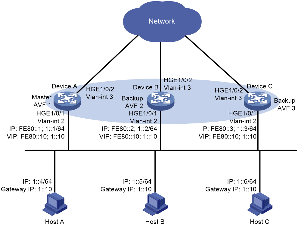
Analysis
To meet the network requirements, you must perform the following tasks:
· To avoid frequent role change in the VRRP group, set a preemption delay.
· For traffic to be switched to the other two devices when the uplink interface of one device fails, configure VF tracking on Device A, Device B, and Device C. When the uplink interface of one device fails, the weights of the VFs (including the AVF) on the device decrease by the specified value.
· For the failed device to become the master when it recovers, configure the preemptive mode for the VRRP group.
Software versions used
This configuration example was created and verified on R3606.
Restrictions and guidelines
When you configure IPv6 VRRP load balancing, follow these restrictions and guidelines:
· For the hosts to access the external network, make sure the following IP addresses are on the same subnet:
¡ The virtual IPv6 address of the VRRP group.
¡ The downlink interface IPv6 addresses of the VRRP group members.
· IPv6 VRRP can use VRRPv2 or VRRPv3 (default version). For an IPv6 VRRP group to operate correctly, make sure the VRRP versions on all devices in the VRRP group are the same.
· In load balancing mode, the virtual IPv6 addresses of a VRRP group cannot be the IPv6 addresses of any interfaces in the VRRP group. Otherwise, VRRP load balancing cannot operate correctly.
· If the uplink of the VF owner fails, an LVF must take over as the AVF. The switchover occurs when the weight of the VF owner drops below the lower limit of failure. This requires the reduced weight for the VF owner to be higher than 245.
· Configure the same virtual IPv6 addresses for each device in the IPv6 VRRP group.
· Make sure the decreased priority of the master is lower than the priority of all the other devices in the IPv6 VRRP group. Another device in the group can then be elected as the master.
· By default, interfaces on the device are disabled (in ADM or Administratively Down state). To have an interface operate, you must use the undo shutdown command to enable that interface.
· The physical interfaces in this example must operate at Layer 2. By default, the interfaces on the device operate at Layer 3. You must use the port link-mode command to change the link mode of the interfaces to Layer 2.
Procedures
Configuring Device A
1. Configure the interfaces:
# Create VLAN 2 and assign HundredGigE 1/0/1 to VLAN 2.
<DeviceA> system-view
[DeviceA] interface hundredgige 1/0/1
[DeviceA-HundredGigE1/0/1] undo shutdown
[DeviceA-HundredGigE1/0/1] quit
[DeviceA] vlan 2
[DeviceA-vlan2] port hundredgige 1/0/1
[DeviceA-vlan2] quit
# Create VLAN-interface 2, and assign IPv6 addresses to the VLAN interface.
[DeviceA] interface vlan-interface 2
[DeviceA-Vlan-interface2] ip address ipv6 address fe80::1 link-local
[DeviceA-Vlan-interface2] ipv6 address 1::1 64
[DeviceA-Vlan-interface2] quit
2. Configure VRRP:
# Configure IPv6 VRRP to operate in load balancing mode.
[DeviceA] vrrp ipv6 mode load-balance
# Create IPv6 VRRP group 1, and set its virtual IPv6 addresses to FE80::10 and 1::10.
[DeviceA] interface vlan-interface 2
[DeviceA-Vlan-interface2] vrrp ipv6 vrid 1 virtual-ip fe80::10 link-local
[DeviceA-Vlan-interface2] vrrp ipv6 vrid 1 virtual-ip 1::10
# Set the priority of Device A to 120 in IPv6 VRRP group 1. Device A has the highest priority in the VRRP group, so Device A can become the master.
[DeviceA-Vlan-interface2] vrrp ipv6 vrid 1 priority 120
# Configure Device A to operate in preemptive mode, and set the preemption delay to 5 seconds.
[DeviceA-Vlan-interface2] vrrp ipv6 vrid 1 preempt-mode delay 500
# Disable RA message suppression on VLAN-interface 2. The hosts on subnet 1::/64 can learn the default gateway address from the RA messages.
[DeviceA-Vlan-interface2] undo ipv6 nd ra halt
[DeviceA-Vlan-interface2] quit
3. Configure Track:
# Create track entry 1 to monitor the link status of the uplink interface HundredGigE 1/0/2. If the uplink interface fails, the track entry transits to Negative.
[DeviceA] track 1 interface hundredgige 1/0/2
[DeviceA-track-1] quit
# Configure the VFs in IPv6 VRRP group 1 to monitor track entry 1, and decrease their weights by 250 when the track entry transits to Negative.
[DeviceA] interface vlan-interface 2
[DeviceA-Vlan-interface2] vrrp ipv6 vrid 1 weight track 1 reduced 250
[DeviceA-Vlan-interface2] quit
Configuring Device B
1. Configure the interfaces:
# Create VLAN 2 and assign HundredGigE 1/0/1 to VLAN 2.
<DeviceB> system-view
[DeviceB] interface hundredgige 1/0/1
[DeviceB-HundredGigE1/0/1] undo shutdown
[DeviceB-HundredGigE1/0/1] quit
[DeviceB] vlan 2
[DeviceB-vlan2] port hundredgige 1/0/1
[DeviceB-vlan2] quit
# Create VLAN-interface 2, and assign IPv6 addresses to the VLAN interface.
[DeviceB] interface vlan-interface 2
[DeviceB-Vlan-interface2] ip address ipv6 address fe80::2 link-local
[DeviceB-Vlan-interface2] ipv6 address 1::2 64
[DeviceB-Vlan-interface2] quit
2. Configure VRRP:
# Configure IPv6 VRRP to operate in load balancing mode.
[DeviceB] vrrp ipv6 mode load-balance
# Create IPv6 VRRP group 1, and set its virtual IPv6 addresses to FE80::10 and 1::10.
[DeviceB] interface vlan-interface 2
[DeviceB-Vlan-interface2] vrrp ipv6 vrid 1 virtual-ip fe80::10 link-local
[DeviceB-Vlan-interface2] vrrp ipv6 vrid 1 virtual-ip 1::10
# Set the priority of Device B to 110 in IPv6 VRRP group 1. Device B has a higher priority than Device C in the VRRP group, so Device B can become the master when Device A fails.
[DeviceB-Vlan-interface2] vrrp ipv6 vrid 1 priority 110
# Configure Device B to operate in preemptive mode, and set the preemption delay to 5 seconds.
[DeviceB-Vlan-interface2] vrrp ipv6 vrid 1 preempt-mode delay 500
# Disable RA message suppression on VLAN-interface 2. The hosts on subnet 1::/64 can learn the default gateway address from the RA messages.
[DeviceB-Vlan-interface2] undo ipv6 nd ra halt
[DeviceB-Vlan-interface2] quit
3. Configure Track:
# Create track entry 1 to monitor the link status of the uplink interface HundredGigE 1/0/2. If the uplink interface fails, the track entry transits to Negative.
[DeviceB] track 1 interface hundredgige 1/0/2
[DeviceB-track-1] quit
# Configure the VFs in IPv6 VRRP group 1 to monitor track entry 1, and decrease their weights by 250 when the track entry transits to Negative.
[DeviceB] interface vlan-interface 2
[DeviceB-Vlan-interface2] vrrp ipv6 vrid 1 weight track 1 reduced 250
[DeviceB-Vlan-interface2] quit
Configuring Device C
1. Configure the interfaces:
# Create VLAN 2 and assign HundredGigE 1/0/1 to VLAN 2.
<DeviceC> system-view
[DeviceC] interface hundredgige 1/0/1
[DeviceC-HundredGigE1/0/1] undo shutdown
[DeviceC-HundredGigE1/0/1] quit
[DeviceC] vlan 2
[DeviceC-vlan2] port hundredgige 1/0/1
[DeviceC-vlan2] quit
# Create VLAN-interface 2, and assign IPv6 addresses to the VLAN interface.
[DeviceC] interface vlan-interface 2
[DeviceC-Vlan-interface2] ipv6 address fe80::3 link-local
[DeviceC-Vlan-interface2] ipv6 address 1::3 64
[DeviceC-Vlan-interface2] quit
2. Configure VRRP:
# Configure VRRP to operate in load balancing mode.
[DeviceC] vrrp ipv6 mode load-balance
# Create IPv6 VRRP group 1, and set its virtual IPv6 addresses to FE80::10 and 1::10.
[DeviceC] interface vlan-interface 2
[DeviceC-Vlan-interface2] vrrp ipv6 vrid 1 virtual-ip fe80::10 link-local
[DeviceC-Vlan-interface2] vrrp ipv6 vrid 1 virtual-ip 1::10
# Configure Device C to operate in preemptive mode, and set the preemption delay to 5 seconds.
[DeviceC-Vlan-interface2] vrrp ipv6 vrid 1 preempt-mode delay 500
# Disable RA message suppression on VLAN-interface 2. The hosts on subnet 1::/64 can learn the default gateway address from the RA messages.
[DeviceC-Vlan-interface2] undo ipv6 nd ra halt
[DeviceC-Vlan-interface2] quit
3. Configure Track:
# Create track entry 1 to monitor the link status of the uplink interface HundredGigE 1/0/2. If the uplink interface fails, the track entry transits to Negative.
[DeviceC] track 1 interface hundredgige 1/0/2
[DeviceC-track-1] quit
# Configure the VFs in IPv6 VRRP group 1 to monitor track entry 1, and decrease their weights by 250 when the track entry transits to Negative.
[DeviceC] interface vlan-interface 2
[DeviceC-Vlan-interface2] vrrp ipv6 vrid 1 weight track 1 reduced 250
[DeviceC-Vlan-interface2] quit
Verifying the configuration
1. Verify that Host A can ping the external network. (Details not shown.)
2. Verify that Device A is operating as the master and Device B and Device C as the backups in IPv6 VRRP group 1. Each of the three devices has one AVF and two LVFs.
# Display detailed information about all IPv6 VRRP groups on Device A.
[DeviceA] display vrrp ipv6 verbose
IPv6 Virtual Device Information:
Running mode : Load balance
Total number of virtual routers : 1
Interface Vlan-interface2
VRID : 1 Adver Timer : 100 centiseconds
Admin Status : Up State : Master
Config Pri : 120 Running Pri : 120
Preempt Mode : Yes Delay Time : 500 centiseconds
Auth Type : None
Virtual IP : FE80::10
1::10
Member IP List : FE80::1 (Local, Master)
FE80::2 (Backup)
FE80::3 (Backup)
Forwarder Information: 3 Forwarders 1 Active
Config Weight : 255
Running Weight : 255
Forwarder 01
State : Active
Virtual MAC : 000f-e2ff-0011 (Owner)
Owner ID : 0000-5e01-1101
Priority : 255
Active : local
Forwarder 02
State : Listening
Virtual MAC : 000f-e2ff-0012 (Learnt)
Owner ID : 0000-5e01-1103
Priority : 127
Active : FE80::2
Forwarder 03
State : Listening
Virtual MAC : 000f-e2ff-0013 (Learnt)
Owner ID : 0000-5e01-1105
Priority : 127
Active : FE80::3
Forwarder Weight Track Information:
Track Object : 1 State : Positive Weight Reduced : 250
# Display detailed information about all IPv6 VRRP groups on Device B.
[DeviceB] display vrrp ipv6 verbose
IPv6 Virtual Device Information:
Running mode : Load balance
Total number of virtual routers : 1
Interface Vlan-interface2
VRID : 1 Adver Timer : 100 centiseconds
Admin Status : Up State : Backup
Config Pri : 110 Running Pri : 110
Preempt Mode : Yes Delay Time : 500 centiseconds
Auth Type : None
Virtual IP : FE80::10
1::10
Member IP List : FE80::2 (Local, Backup)
FE80::1 (Master)
FE80::3 (Backup)
Forwarder Information: 3 Forwarders 1 Active
Config Weight : 255
Running Weight : 255
Forwarder 01
State : Listening
Virtual MAC : 000f-e2ff-0011 (Learnt)
Owner ID : 0000-5e01-1101
Priority : 127
Active : FE80::1
Forwarder 02
State : Active
Virtual MAC : 000f-e2ff-0012 (Owner)
Owner ID : 0000-5e01-1103
Priority : 255
Active : local
Forwarder 03
State : Listening
Virtual MAC : 000f-e2ff-0013 (Learnt)
Owner ID : 0000-5e01-1105
Priority : 127
Active : FE80::3
Forwarder Weight Track Information:
Track Object : 1 State : Positive Weight Reduced : 250
# Display detailed information about all VRRP groups on Device C.
[DeviceC] display vrrp ipv6 verbose
IPv4 Virtual Device Information:
Running mode : Load balance
Total number of virtual routers : 1
Interface Vlan-interface2
VRID : 1 Adver Timer : 100 centiseconds
Admin Status : Up State : Backup
Config Pri : 100 Running Pri : 100 centiseconds
Preempt Mode : Yes Delay Time : 500
Auth Type : None
Virtual IP : FE80::10
1::10
Member IP List : FE80::3 (Local, Backup)
FE80::1 (Master)
FE80::2 (Backup)
Forwarder Information: 3 Forwarders 1 Active
Config Weight : 255
Running Weight : 255
Forwarder 01
State : Listening
Virtual MAC : 000f-e2ff-0011 (Learnt)
Owner ID : 0000-5e01-1101
Priority : 127
Active : FE80::1
Forwarder 02
State : Listening
Virtual MAC : 000f-e2ff-0012 (Learnt)
Owner ID : 0000-5e01-1103
Priority : 127
Active : FE80::2
Forwarder 03
State : Active
Virtual MAC : 000f-e2ff-0013 (Owner)
Owner ID : 0000-5e01-1105
Priority : 255
Active : local
Forwarder Weight Track Information:
Track Object : 1 State : Positive Weight Reduced : 250
3. Verify that AVF switchover can be performed when the uplink interface HundredGigE 1/0/2 of Device A fails.
# Display detailed information about all IPv6 VRRP groups on Device A.
[DeviceA] display vrrp ipv6 verbose
IPv6 Virtual Device Information:
Running mode : Load balance
Total number of virtual routers : 1
Interface Vlan-interface2
VRID : 1 Adver Timer : 100 centiseconds
Admin Status : Up State : Master
Config Pri : 120 Running Pri : 120
Preempt Mode : Yes Delay Time : 500 centiseconds
Auth Type : None
Virtual IP : FE80::10
1::10
Member IP List : FE80::1 (Local, Master)
FE80::2 (Backup)
FE80::3 (Backup)
Forwarder Information: 3 Forwarders 0 Active
Config Weight : 255
Running Weight : 5
Forwarder 01
State : Initialize
Virtual MAC : 000f-e2ff-0011 (Owner)
Owner ID : 0000-5e01-1101
Priority : 0
Active : FE80::3
Forwarder 02
State : Initialize
Virtual MAC : 000f-e2ff-0012 (Learnt)
Owner ID : 0000-5e01-1103
Priority : 0
Active : FE80::2
Forwarder 03
State : Initialize
Virtual MAC : 000f-e2ff-0013 (Learnt)
Owner ID : 0000-5e01-1105
Priority : 0
Active : FE80::3
Forwarder Weight Track Information:
Track Object : 1 State : Negative Weight Reduced : 250
# Display detailed information about all IPv6 VRRP groups on Device C.
[DeviceC] display vrrp ipv6 verbose
IPv6 Virtual Device Information:
Running mode : Load balance
Total number of virtual routers : 1
Interface Vlan-interface2
VRID : 1 Adver Timer : 100 centiseconds
Admin Status : Up State : Backup
Config Pri : 100 Running Pri : 100
Preempt Mode : Yes Delay Time : 500 centiseconds
Auth Type : None
Become Master : 3550ms left
Virtual IP : FE80::10
1::10
Member IP List : FE80::3 (Local, Backup)
FE80::1 (Master)
FE80::2 (Backup)
Forwarder Information: 3 Forwarders 2 Active
Config Weight : 255
Running Weight : 255
Forwarder 01
State : Active
Virtual MAC : 000f-e2ff-0011 (Take Over)
Owner ID : 0000-5e01-1101
Priority : 85
Active : local
Redirect Time : 93 secs
Time-out Time : 1293 secs
Forwarder 02
State : Listening
Virtual MAC : 000f-e2ff-0012 (Learnt)
Owner ID : 0000-5e01-1103
Priority : 85
Active : FE80::2
Forwarder 03
State : Active
Virtual MAC : 000f-e2ff-0013 (Owner)
Owner ID : 0000-5e01-1105
Priority : 255
Active : local
Forwarder Weight Track Information:
Track Object : 1 State : Positive Weight Reduced : 250
The output shows that the weights of the VFs on Device A drop below the lower limit of failure when the uplink interface HundredGigE 1/0/2 of Device A fails. All VFs on Device A transit to Initialized state and cannot forward traffic. The VF for MAC address 000f-e2ff-0011 on Device C becomes the AVF to forward traffic.
4. Verify that the VF for virtual MAC address 000f-e2ff-0011 is removed from Device C when the timeout timer (about 1800 seconds) expires. The VF no longer forwards the packets destined for the MAC address.
[DeviceC] display vrrp ipv6 verbose
IPv6 Virtual Device Information:
Running mode : Load balance
Total number of virtual routers : 1
Interface Vlan-interface2
VRID : 1 Adver Timer : 100 centiseconds
Admin Status : Up State : Backup
Config Pri : 100 Running Pri : 100
Preempt Mode : Yes Delay Time : 500 centiseconds
Auth Type : None
Become Master : 3550ms left
Virtual IP : FE80::10
1::10
Member IP List : FE80::3 (Local, Backup)
FE80::1 (Master)
FE80::2 (Backup)
Forwarder Information: 2 Forwarders 1 Active
Config Weight : 255
Running Weight : 255
Forwarder 02
State : Listening
Virtual MAC : 000f-e2ff-0012 (Learnt)
Owner ID : 0000-5e01-1103
Priority : 127
Active : FE80::2
Forwarder 03
State : Active
Virtual MAC : 000f-e2ff-0013 (Owner)
Owner ID : 0000-5e01-1105
Priority : 255
Active : local
Forwarder Weight Track Information:
Track Object : 1 State : Positive Weight Reduced : 250
5. Verify that Device B has a higher priority than Device C and becomes the master when Device A fails.
[DeviceB] display vrrp ipv6 verbose
IPv6 Standby Information:
Run mode : Load balance
Run Method : Virtual MAC
Total number of virtual routers : 1
Interface Vlan-interface2
VRID : 1 Adver Timer : 1 centiseconds
Admin Status : Up State : Master
Config Pri : 110 Running Pri : 110
Preempt Mode : Yes Delay Time : 500 centiseconds
Auth Type : None
Virtual IP : FE80::10
1::10
Member IP List : FE80::2 (Local, Master)
FE80::3 (Backup)
Forwarder Information: 2 Forwarders 1 Active
Config Weight : 255
Running Weight : 255
Forwarder 02
State : Active
Virtual MAC : 000f-e2ff-0012 (Owner)
Owner ID : 0000-5e01-1103
Priority : 255
Active : local
Forwarder 03
State : Listening
Virtual MAC : 000f-e2ff-0013 (Learnt)
Owner ID : 0000-5e01-1105
Priority : 127
Active : FE80::3
Forwarder Weight Track Information:
Track Object : 1 State : Positive Weight Reduced : 250
Configuration files
· Device A:
#
vrrp ipv6 mode load-balance
#
vlan 2 to 3
#
interface Vlan-interface2
ipv6 address fe80::1 link-local
ipv6 address 1::1 64
undo ipv6 nd ra halt
vrrp ipv6 vrid 1 virtual-ip fe80::10 link-local
vrrp ipv6 vrid 1 virtual-ip 1::10
vrrp ipv6 vrid 1 priority 120
vrrp ipv6 vrid 1 preempt-mode delay 500
vrrp ipv6 vrid 1 weight track 1 reduced 250
#
interface Vlan-interface3
#
interface HundredGigE1/0/1
port link-mode bridge
port access vlan 2
#
interface HundredGigE1/0/2
port link-mode bridge
port access vlan 3
#
track 1 interface vlan-interface3
#
· Device B:
#
vrrp ipv6 mode load-balance
#
vlan 2 to 3
#
interface Vlan-interface2
ipv6 address fe80::2 link-local
ipv6 address 1::2 64
undo ipv6 nd ra halt
vrrp ipv6 vrid 1 virtual-ip fe80::10 link-local
vrrp ipv6 vrid 1 virtual-ip 1::10
vrrp ipv6 vrid 1 priority 110
vrrp ipv6 vrid 1 preempt-mode delay 500
vrrp ipv6 vrid 1 weight track 1 reduced 250
#
interface Vlan-interface3
#
interface HundredGigE1/0/1
port link-mode bridge
port access vlan 2
#
interface HundredGigE1/0/2
port link-mode bridge
port access vlan 3
#
track 1 interface vlan-interface3
#
· Device C:
#
vrrp ipv6 mode load-balance
#
vlan 2 to 3
#
interface Vlan-interface2
ipv6 address fe80::3 link-local
ipv6 address 1::3 64
undo ipv6 nd ra halt
vrrp ipv6 vrid 1 virtual-ip fe80::10 link-local
vrrp ipv6 vrid 1 virtual-ip 1::10
vrrp ipv6 vrid 1 preempt-mode delay 500
vrrp ipv6 vrid 1 weight track 1 reduced 250
#
interface Vlan-interface3
#
interface HundredGigE1/0/1
port link-mode bridge
port access vlan 2
#
interface HundredGigE1/0/2
port link-mode bridge
port access vlan 3
#
track 1 interface vlan-interface3
#
Example: Configuring VRRP with Ethernet link aggregation
Network configuration
As shown in Figure 7, Device A, Device B, and L2switch are connected to one another through aggregate links to improve link reliability.
Configure a VRRP group on Device A and Device B as the gateway for the hosts in Area A to meet the following requirements:
· Device A operates as the master to forward packets from the hosts in Area A to the external network.
· If the uplink interface of Device A fails, the hosts in Area A can access the external network through Device B.
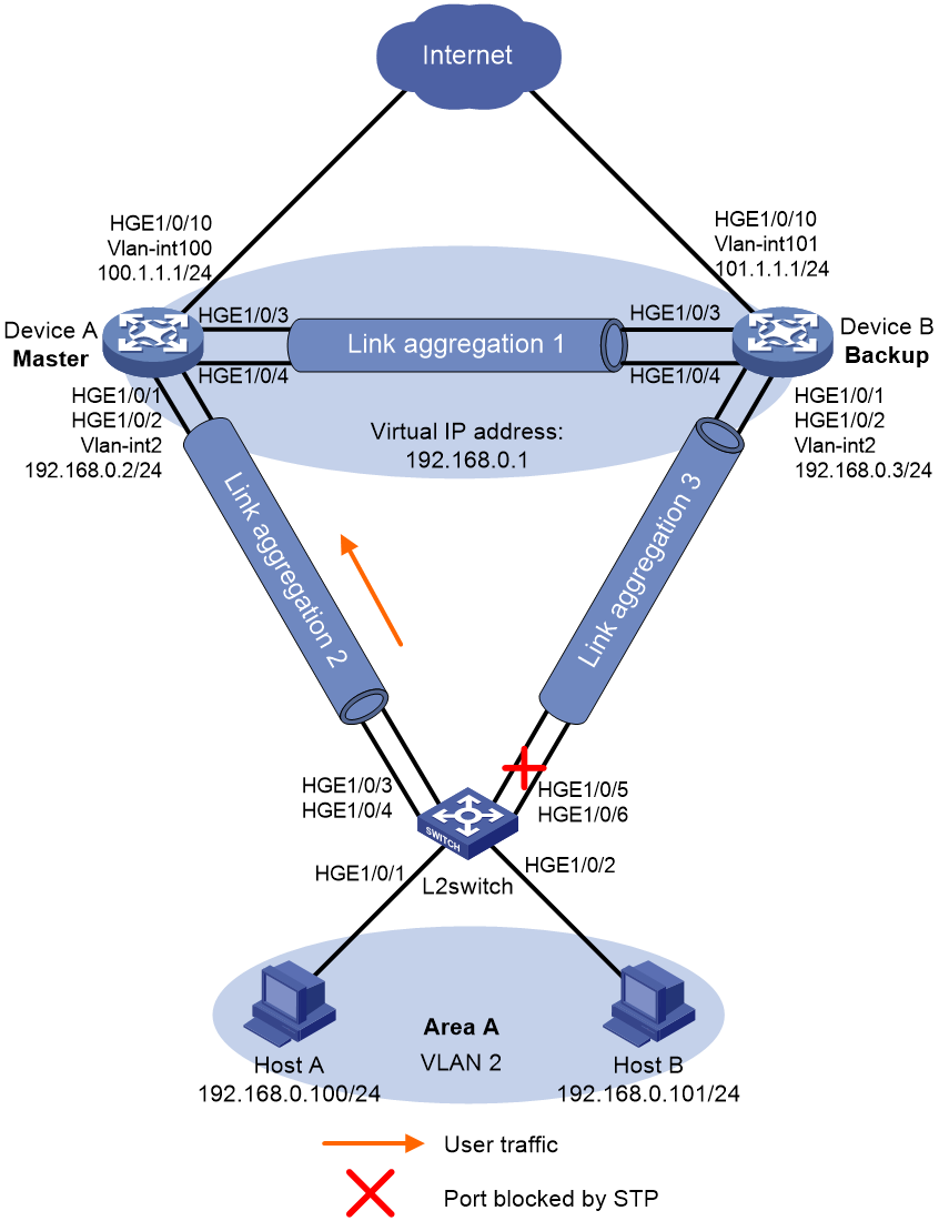
Analysis
To meet the network requirements, you must perform the following tasks:
· For Device A to become the master when it recovers from a failure, configure the preemptive mode for the VRRP group.
· For Device A to decrease its priority and become a backup when its uplink interface fails, configure VRRP tracking on Device A.
· To avoid frequent role change in the VRRP group, set a preemption delay.
· To avoid loops between Device A, Device B, and L2switch, use the spanning tree feature to block a port in the VRRP group.
Software versions used
This configuration example was created and verified on R3606.
Restrictions and guidelines
When you configure VRRP with Ethernet link aggregation, follow these restrictions and guidelines:
· For the hosts in Area A to access the external network, make sure the following IP addresses are on the same subnet:
¡ The virtual IP address of the VRRP group.
¡ The downlink interface IP addresses of the VRRP group members.
· IPv4 VRRP can use VRRPv2 or VRRPv3 (default version). For a VRRP group to operate correctly, make sure the VRRP versions on all devices in the VRRP group are the same.
· Removal of the VRRP group on the IP address owner causes IP address collision. To avoid a collision, change the IP address of the interface on the IP address owner before you remove the VRRP group from the interface.
· Configure the same virtual IP addresses for each device in the VRRP group.
· Make sure the decreased priority of the master is lower than the priority of all the other devices in the VRRP group. Another device in the group can then be elected as the master.
· You must configure the same aggregation mode on both ends of an aggregate link.
· Deleting an aggregate interface also deletes the aggregation group. At the same time, the member ports of the aggregation group, if any, leave the aggregation group.
· You cannot assign a port to a Layer 2 aggregation group if any of the following features are configured on the port:
¡ Association between AC and cross-connect. (See H3C S12500R Switch Router Series MPLS Configuration Guide.)
¡ Association between AC and VSI. (See H3C S12500R Switch Router Series VXLAN Configuration Guide.)
· By default, interfaces on the device are disabled (in ADM or Administratively Down state). To have an interface operate, you must use the undo shutdown command to enable that interface.
· The physical interfaces in this example must operate at Layer 2. By default, the interfaces on the device operate at Layer 3. You must use the port link-mode command to change the link mode of the interfaces to Layer 2.
Procedures
Configuring Device A
# Create the Layer 2 aggregate interface Bridge-aggregation 1.
<DeviceA> system-view
[DeviceA] interface bridge-aggregation 1
[DeviceA-Bridge-Aggregation1] quit
# Assign the ports HundredGigE 1/0/3 and HundredGigE 1/0/4 to Layer 2 aggregation group 1.
[DeviceA] interface hundredgige 1/0/3
[DeviceA-HundredGigE1/0/3] port link-aggregation group 1
[DeviceA-HundredGigE1/0/3] quit
[DeviceA] interface hundredgige 1/0/4
[DeviceA-HundredGigE1/0/4] port link-aggregation group 1
[DeviceA-HundredGigE1/0/4] quit
# Configure Bridge-Aggregation 1 as a trunk port, and assign it to all VLANs.
[DeviceA] interface bridge-aggregation 1
[DeviceA-Bridge-Aggregation1] port link-type trunk
[DeviceA-Bridge-Aggregation1] port trunk permit vlan all
[DeviceA-Bridge-Aggregation1] quit
# Create the Layer 2 aggregate interface Bridge-Aggregation 2.
[DeviceA] interface bridge-aggregation 2
[DeviceA-Bridge-Aggregation2] quit
# Assign the ports HundredGigE 1/0/1 and HundredGigE 1/0/2 to Layer 2 aggregation group 2.
[DeviceA] interface hundredgige 1/0/1
[DeviceA-HundredGigE1/0/1] port link-aggregation group 2
[DeviceA-HundredGigE1/0/1] quit
[DeviceA] interface hundredgige 1/0/2
[DeviceA-HundredGigE1/0/2] port link-aggregation group 2
[DeviceA-HundredGigE1/0/2] quit
# Create VLAN 2 and VLAN-interface 2, and assign an IP address to the VLAN interface.
[DeviceA] vlan 2
[DeviceA-vlan2] quit
[DeviceA] interface vlan-interface 2
[DeviceA-Vlan-interface2] ip address 192.168.0.2 24
[DeviceA-Vlan-interface2] quit
# Configure Bridge-Aggregation 2 as an access port, and assign the port to VLAN 2.
[DeviceA] interface bridge-aggregation 2
[DeviceA-Bridge-Aggregation2] port link-type access
[DeviceA-Bridge-Aggregation2] port access vlan 2
[DeviceA-Bridge-Aggregation2] quit
# Create VRRP group 1, and set its virtual IP address to 192.168.0.1.
[DeviceA] interface vlan-interface 2
[DeviceA-Vlan-interface2] vrrp vrid 1 virtual-ip 192.168.0.1
# Set the priority of Device A to 110 in VRRP group 1. Device A has a higher priority than Device B in the VRRP group, so Device A can become the master.
[DeviceA-Vlan-interface2] vrrp vrid 1 priority 110
# Configure Device A to operate in preemptive mode, and set the preemption delay to 5 seconds.
[DeviceA-Vlan-interface2] vrrp vrid 1 preempt-mode delay 500
[DeviceA-Vlan-interface2] quit
# Create track entry 1 to monitor the link status of the uplink interface HundredGigE 1/0/10.
[DeviceA] track 1 interface hundredgige 1/0/10
[DeviceA-track-1] quit
# Associate VRRP group 1 with track entry 1 and decrease the device priority by 50 when the state of track entry 1 changes to Negative.
[DeviceA] interface vlan-interface 2
[DeviceA-Vlan-interface2] vrrp vrid 1 track 1 priority reduced 50
[DeviceA-Vlan-interface2] quit
# Configure MSTP, map VLAN 2 to MSTI 1, and configure Device A as the root bridge of MSTI 1.
[DeviceA] stp region-configuration
[DeviceA-mst-region] region-name vrrp
[DeviceA-mst-region] instance 1 vlan 2
[DeviceA-mst-region] active region-configuration
[DeviceA-mst-region] quit
[DeviceA] stp instance 1 root primary
# Enable the spanning tree feature globally.
[DeviceA] stp global enable
Configuring Device B
# Create the Layer 2 aggregate interface Bridge-Aggregation 1.
<DeviceB> system-view
[DeviceB] interface bridge-aggregation 1
[DeviceB-Bridge-Aggregation1] quit
# Assign the ports HundredGigE 1/0/3 and HundredGigE 1/0/4 to Layer 2 aggregation group 1.
[DeviceB] interface hundredgige 1/0/3
[DeviceB-HundredGigE1/0/3] port link-aggregation group 1
[DeviceB-HundredGigE1/0/3] quit
[DeviceB] interface hundredgige 1/0/4
[DeviceB-HundredGigE1/0/4] port link-aggregation group 1
[DeviceB-HundredGigE1/0/4] quit
# Configure Bridge-Aggregation 1 as a trunk port, and assign it to all VLANs.
[DeviceB] interface bridge-aggregation 1
[DeviceB-Bridge-Aggregation1] port link-type trunk
[DeviceB-Bridge-Aggregation1] port trunk permit vlan all
[DeviceB-Bridge-Aggregation1] quit
# Create the Layer 2 aggregate interface Bridge-Aggregation 3.
[DeviceB] interface bridge-aggregation 3
[DeviceB-Bridge-Aggregation3] quit
# Assign the ports HundredGigE 1/0/1 and HundredGigE 1/0/2 to Layer 2 aggregation group 3.
[DeviceB] interface hundredgige 1/0/1
[DeviceB-HundredGigE1/0/1] port link-mode bridge
[DeviceB-HundredGigE1/0/1] port link-aggregation group 3
[DeviceB-HundredGigE1/0/1] quit
[DeviceB] interface hundredgige 1/0/2
[DeviceB-HundredGigE1/0/2] port link-mode bridge
[DeviceB-HundredGigE1/0/2] port link-aggregation group 3
[DeviceB-HundredGigE1/0/2] quit
# Create VLAN 2 and VLAN-interface 2, and assign an IP address to the VLAN interface.
[DeviceB] vlan 2
[DeviceB-vlan2] quit
[DeviceB] interface vlan-interface 2
[DeviceB-Vlan-interface2] ip address 192.168.0.3 24
[DeviceB-Vlan-interface2] quit
# Configure Bridge-Aggregation 3 as an access port, and assign the port to VLAN 2.
[DeviceB] interface bridge-aggregation 3
[DeviceB-Bridge-Aggregation3] port link-type access
[DeviceB-Bridge-Aggregation3] port access vlan 2
[DeviceB-Bridge-Aggregation3] quit
# Create VRRP group 1, and set its virtual IP address to 192.168.0.1.
[DeviceB] interface vlan-interface 2
[DeviceB-Vlan-interface2] vrrp vrid 1 virtual-ip 192.168.0.1
# Configure Device B to operate in preemptive mode, and set the preemption delay to 5 seconds.
[DeviceB-Vlan-interface2] vrrp vrid 1 preempt-mode delay 500
[DeviceB-Vlan-interface2] quit
# Configure MSTP, map VLAN 2 to MSTI 1, and configure Device B as a secondary root bridge in MSTI 1.
[DeviceB] stp region-configuration
[DeviceB-mst-region] region-name vrrp
[DeviceB-mst-region] instance 1 vlan 2
[DeviceB-mst-region] active region-configuration
[DeviceB-mst-region] quit
[DeviceB] stp instance 1 root secondary
# Enable the spanning tree feature globally.
[DeviceB] stp global enable
Configuring L2switch
# Create the Layer 2 aggregate interface Bridge-Aggregation 2.
<L2switch> system-view
[L2switch] interface bridge-aggregation 2
[L2switch-Bridge-Aggregation2] quit
# Assign the ports HundredGigE 1/0/3 and HundredGigE 1/0/4 to Layer 2 aggregation group 2.
[L2switch] interface hundredgige 1/0/3
[L2switch-HundredGigE1/0/3] port link-aggregation group 2
[L2switch-HundredGigE1/0/3] quit
[L2switch] interface hundredgige 1/0/4
[L2switch-HundredGigE1/0/4] port link-aggregation group 2
[L2switch-HundredGigE1/0/4] quit
# Create the Layer 2 aggregate interface Bridge-Aggregation 3.
[L2switch] interface bridge-aggregation 3
[L2switch-Bridge-Aggregation3] quit
# Assign the ports HundredGigE 1/0/5 and HundredGigE 1/0/6 to Layer 2 aggregation group 3.
[L2switch] interface hundredgige 1/0/5
[L2switch-HundredGigE1/0/5] port link-aggregation group 3
[L2switch-HundredGigE1/0/5] quit
[L2switch] interface hundredgige 1/0/6
[L2switch-HundredGigE1/0/6] port link-aggregation group 3
[L2switch-HundredGigE1/0/6] quit
# Create VLAN 2, configure Bridge-Aggregation 2 and Bridge-Aggregation 3 as access ports, and assign the aggregate interfaces to VLAN 2.
[L2switch] vlan 2
[L2switch-vlan2] quit
[L2switch] interface bridge-aggregation 2
[L2switch-Bridge-Aggregation2] port access vlan 2
[L2switch-Bridge-Aggregation2] quit
[L2switch] interface bridge-aggregation 3
[L2switch-Bridge-Aggregation3] port access vlan 2
[L2switch-Bridge-Aggregation3] quit
# Set the MST region name of the device to vrrp.
[L2switch] stp region-configuration
[L2switch-mst-region] region-name vrrp
# Map VLAN 2 to MSTI 1, and activate the MST region configuration.
[L2switch-mst-region] instance 1 vlan 2
[L2switch-mst-region] active region-configuration
[L2switch-mst-region] quit
# Enable the spanning tree feature globally.
[L2switch] stp global enable
Verifying the configuration
1. Verify that Host A in Area A can ping the IP address 20.1.1.1.
Microsoft Windows [Version 6.1.7601]
Copyright (c) 2009 Microsoft Corporation. All rights reserved.
C:\Users\hostA>ping 20.1.1.1
Pinging 20.1.1.1 with 32 bytes of data:
Reply from 20.1.1.1: bytes=32 time<1ms TTL=128
Reply from 20.1.1.1: bytes=32 time<1ms TTL=128
Reply from 20.1.1.1: bytes=32 time<1ms TTL=128
Reply from 20.1.1.1: bytes=32 time<1ms TTL=128
Ping statistics for 20.1.1.1:
Packets: Sent = 4, Received = 4, Lost = 0 (0% loss),
Approximate round trip times in milli-seconds:
Minimum = 0ms, Maximum = 0ms, Average = 0ms
2. Verify that Device A is operating as the master and Device B as the backup in VRRP group 1. Device A forwards packets from the hosts in Area A to the external network.
# Display detailed information about all VRRP groups on Device A.
[DeviceA] display vrrp verbose
IPv4 Virtual Router Information:
Running mode : Standard
Total number of virtual routers : 1
Interface Vlan-interface2
VRID : 1 Adver Timer : 100 centiseconds
Admin Status : Up State : Master
Config Pri : 110 Running Pri : 110
Preempt Mode : Yes Delay Time : 500 centiseconds
Auth Type : None
Virtual IP : 192.168.0.1
Virtual MAC : 0000-5e00-0101
Master IP : 192.168.0.2
VRRP Track Information:
Track Object : 1 State : Positive Pri Reduced : 50
# Display detailed information about all VRRP groups on Device B.
[DeviceB] display vrrp verbose
IPv4 Virtual Router Information:
Running mode : Standard
Total number of virtual routers : 1
Interface Vlan-interface2
VRID : 1 Adver Timer : 100 centiseconds
Admin Status : Up State : Backup
Config Pri : 100 Running Pri : 100
Preempt Mode : Yes Delay Time : 500 centiseconds
Become Master : 2950ms left
Auth Type : None
Virtual IP : 192.168.0.1
Virtual MAC : 0000-5e00-0101
Master IP : 192.168.0.2
3. Verify that link aggregation groups are successfully configured on Device A, Device B, and L2switch.
# Display brief information about all Layer 2 aggregate interfaces on Device A.
[DeviceA] display interface Bridge-Aggregation brief
Brief information on interfaces in bridge mode:
Link: ADM - administratively down; Stby - standby
Speed: (a) - auto
Duplex: (a)/A - auto; H - half; F - full
Type: A - access; T - trunk; H - hybrid
Interface Link Speed Duplex Type PVID Description
BAGG1 UP 2G(a) F(a) A 1
BAGG2 UP 2G(a) F(a) A 2
# Display brief information about all Layer 2 aggregate interfaces on Device B.
[DeviceB] display interface Bridge-Aggregation brief
Brief information on interfaces in bridge mode:
Link: ADM - administratively down; Stby - standby
Speed: (a) - auto
Duplex: (a)/A - auto; H - half; F - full
Type: A - access; T - trunk; H - hybrid
Interface Link Speed Duplex Type PVID Description
BAGG1 UP 2G(a) F(a) A 1
BAGG3 UP 2G(a) F(a) A 2
# Display brief information about all Layer 2 aggregate interfaces on L2switch.
[L2switch] display interface Bridge-Aggregation brief
Brief information on interfaces in bridge mode:
Link: ADM - administratively down; Stby - standby
Speed: (a) - auto
Duplex: (a)/A - auto; H - half; F - full
Type: A - access; T - trunk; H - hybrid
Interface Link Speed Duplex Type PVID Description
BAGG2 UP 2G(a) F(a) A 2
BAGG3 UP 2G(a) F(a) A 2
The output shows that the speed of each aggregate link is 2 Gbps, and the bandwidth is twice the bandwidth of each physical link.
4. Verify that Host A can still ping the IP address 20.1.1.1 after the uplink interface HundredGigE 1/0/10 of Device A fails.
Microsoft Windows [Version 6.1.7601]
Copyright (c) 2009 Microsoft Corporation. All rights reserved.
C:\Users\hostA>ping 20.1.1.1
Pinging 20.1.1.1 with 32 bytes of data:
Reply from 20.1.1.1: bytes=32 time<1ms TTL=128
Reply from 20.1.1.1: bytes=32 time<1ms TTL=128
Reply from 20.1.1.1: bytes=32 time<1ms TTL=128
Reply from 20.1.1.1: bytes=32 time<1ms TTL=128
Ping statistics for 20.1.1.1:
Packets: Sent = 4, Received = 4, Lost = 0 (0% loss),
Approximate round trip times in milli-seconds:
Minimum = 0ms, Maximum = 0ms, Average = 0ms
5. Verify that Device B takes over to forward packets from the hosts in Area A to the external network after HundredGigE 1/0/10 of Device A fails.
# Display detailed information about all VRRP groups on Device A.
[DeviceA] display vrrp verbose
IPv4 Virtual Router Information:
Running mode : Standard
Total number of virtual routers : 1
Interface Vlan-interface2
VRID : 1 Adver Timer : 100 centiseconds
Admin Status : Up State : Backup
Config Pri : 110 Running Pri : 60
Preempt Mode : Yes Delay Time : 500 centiseconds
Become Master : 3350ms left
Auth Type : None
Virtual IP : 192.168.0.1
Master IP : 192.168.0.3
VRRP Track Information:
Track Object : 1 State : Negative Pri Reduced : 50
# Display detailed information about all VRRP groups on Device B.
[DeviceB] display vrrp verbose
IPv4 Virtual Router Information:
Running mode : Standard
Total number of virtual routers : 1
Interface Vlan-interface2
VRID : 1 Adver Timer : 100 centiseconds
Admin Status : Up State : Master
Config Pri : 100 Running Pri : 100
Preempt Mode : Yes Delay Time : 500 centiseconds
Auth Type : None
Virtual IP : 192.168.0.1
Virtual MAC : 0000-5e00-0101
Master IP : 192.168.0.3
6. Verify that Device A becomes the master to forward packets from the hosts in Area A to the external network when HundredGigE 1/0/10 recovers.
# Display detailed information about all VRRP groups on Device A.
[DeviceA] display vrrp verbose
IPv4 Virtual Router Information:
Running mode : Standard
Total number of virtual routers : 1
Interface Vlan-interface2
VRID : 1 Adver Timer : 100 centiseconds
Admin Status : Up State : Master
Config Pri : 110 Running Pri : 110
Preempt Mode : Yes Delay Time : 500 centiseconds
Auth Type : None
Virtual IP : 192.168.0.1
Virtual MAC : 0000-5e00-0101
Master IP : 192.168.0.2
VRRP Track Information:
Track Object : 1 State : Positive Pri Reduced : 50
# Display detailed information about all VRRP groups on Device B.
[DeviceB] display vrrp verbose
IPv4 Virtual Router Information:
Running mode : Standard
Total number of virtual routers : 1
Interface Vlan-interface2
VRID : 1 Adver Timer : 100 centiseconds
Admin Status : Up State : Backup
Config Pri : 100 Running Pri : 100
Preempt Mode : Yes Delay Time : 500 centiseconds
Become Master : 2950ms left
Auth Type : None
Virtual IP : 192.168.0.1
Virtual MAC : 0000-5e00-0101
Master IP : 192.168.0.2
Configuration files
· Device A:
#
sysname DeviceA
#
vlan 2
#
stp region-configuration
region-name vrrp
instance 1 vlan 2
active region-configuration
#
stp instance 1 root primary
stp global enable
#
interface Bridge-Aggregation1
port link-type trunk
port trunk permit vlan all
#
interface Bridge-Aggregation2
port access vlan 2
#
interface Vlan-interface2
ip address 192.168.0.2 255.255.255.0
vrrp vrid 1 virtual-ip 192.168.0.1
vrrp vrid 1 priority 110
vrrp vrid 1 preempt-mode delay 500
vrrp vrid 1 track 1 priority reduced 50
#
interface HundredGigE1/0/1
port link-mode bridge
port access vlan 2
port link-aggregation group 2
#
interface HundredGigE1/0/2
port link-mode bridge
port access vlan 2
port link-aggregation group 2
#
interface HundredGigE1/0/3
port link-mode bridge
port link-type trunk
port trunk permit vlan all
port link-aggregation group 1
#
interface HundredGigE1/0/4
port link-mode bridge
port link-type trunk
port trunk permit vlan all
port link-aggregation group 1
#
track 1 interface HundredGigE1/0/10
#
· Device B:
#
sysname DeviceB
#
vlan 2
#
stp region-configuration
region-name vrrp
instance 1 vlan 2
active region-configuration
#
stp instance 1 root secondary
stp global enable
#
interface Bridge-Aggregation1
port link-type trunk
port trunk permit vlan all
#
interface Bridge-Aggregation2
port access vlan 2
#
interface Vlan-interface2
ip address 192.168.0.3 255.255.255.0
vrrp vrid 1 virtual-ip 192.168.0.1
vrrp vrid 1 preempt-mode delay 500
#
interface HundredGigE1/0/1
port link-mode bridge
port access vlan 2
port link-aggregation group 3
#
interface HundredGigE1/0/2
port link-mode bridge
port access vlan 2
port link-aggregation group 3
#
interface HundredGigE1/0/3
port link-mode bridge
port link-type trunk
port trunk permit vlan all
port link-aggregation group 1
#
interface HundredGigE1/0/4
port link-mode bridge
port link-type trunk
port trunk permit vlan all
port link-aggregation group 1
#
· L2switch:
#
sysname L2switch
#
vlan 2
#
stp region-configuration
region-name vrrp
instance 1 vlan 2
active region-configuration
#
stp global enable
#
interface Bridge-Aggregation2
port access vlan 2
#
interface Bridge-Aggregation3
port access vlan 2
#
interface HundredGigE1/0/3
port link-mode bridge
port access vlan 2
port link-aggregation group 2
#
interface HundredGigE1/0/2
port link-mode bridge
port access vlan 2
port link-aggregation group 2
#
interface HundredGigE1/0/4
port link-mode bridge
port access vlan 2
port link-aggregation group 2
#
interface HundredGigE1/0/5
port link-mode bridge
port access vlan 2
port link-aggregation group 3
#
interface HundredGigE1/0/6
port link-mode bridge
port access vlan 2
port link-aggregation group 3
#
Related documentation
· H3C S12500R Switch Router Series High Availability Command Reference-R3606
· H3C S12500R Switch Router Series High Availability Configuration Guide-R3606
· H3C S12500R Switch Router Series Layer 2—LAN Switching Command Reference-R3606
· H3C S12500R Switch Router Series Layer 2—LAN Switching Configuration Guide-R3606
