- Table of Contents
-
- H3C S12500R Ethernet Switch Router Series Config Examples-Release 36xx-6W100
- 01-Login Management Configuration Examples
- 02-RBAC Configuration Examples
- 03-Software Upgrade Examples
- 04-Ethernet Link Aggregation Configuration Examples
- 05-Port Isolation Configuration Examples
- 06-Spanning Tree Configuration Examples
- 07-VLAN Configuration Examples
- 08-VLAN Tagging Configuration Examples
- 09-DHCP Snooping Configuration Examples
- 10-Cross-Subnet Dynamic IP Address Allocation Configuration Examples
- 11-IPv6 over IPv4 Tunneling with OSPFv3 Configuration Examples
- 12-GRE Tunnel Configuration Examples
- 13-GRE with OSPF Configuration Examples
- 14-OSPF Configuration Examples
- 15-IS-IS Configuration Examples
- 16-BGP Configuration Examples
- 17-Policy-Based Routing Configuration Examples
- 18-OSPFv3 Configuration Examples
- 19-IPv6 IS-IS Configuration Examples
- 20-Routing Policy Configuration Examples
- 21-IGMP Snooping Configuration Examples
- 22-IGMP Configuration Examples
- 23-MLD Snooping Configuration Examples
- 24-Basic MPLS Configuration Examples
- 25-MPLS L3VPN Configuration Examples
- 26-ACL Configuration Examples
- 27-Control Plane-Based QoS Policy Configuration Examples
- 28-Traffic Policing Configuration Examples
- 29-GTS and Rate Limiting Configuration Examples
- 30-Priority Mapping and Queue Scheduling Configuration Examples
- 31-Traffic Filtering Configuration Examples
- 32-AAA Configuration Examples
- 33-SSH Configuration Examples
- 34-IP Source Guard Configuration Examples
- 35-Ethernet OAM Configuration Examples
- 36-CFD Configuration Examples
- 37-DLDP Configuration Examples
- 38-VRRP Configuration Examples
- 39-BFD Configuration Examples
- 40-NTP Configuration Examples
- 41-SNMP Configuration Examples
- 42-NQA Configuration Examples
- 43-Mirroring Configuration Examples
- 44-sFlow Configuration Examples
- 45-OpenFlow Configuration Examples
- 46-MAC Address Table Configuration Examples
- 47-Static Multicast MAC Address Entry Configuration Examples
- 48-IP Unnumbered Configuration Examples
- 49-Congestion Avoidance and Queue Scheduling Configuration Examples
- 50-Attack Protection Configuration Examples
- 51-Smart Link Configuration Examples
- 52-RRPP Configuration Examples
- 53-BGP Route Selection Configuration Examples
- 54-IS-IS Route Summarization Configuration Examples
- 55-MPLS OAM Configuration Examples
- 56-MPLS TE Configuration Examples
- 57-VXLAN Configuration Examples
- 58-NetStream Configuration Examples
- 59-EVPN-DCI over an MPLS L3VPN Network Configuration Examples
- 60-PTP Configuration Examples
- 61-S-MLAG Configuration Examples
- 62-MPLS SR Configuration Examples
- 63-Puppet Configuration Examples
- Related Documents
-
| Title | Size | Download |
|---|---|---|
| 17-Policy-Based Routing Configuration Examples | 69.59 KB |
|
|
|
H3C S12500R Switch Router Series |
|
Policy-Based Routing Configuration Examples |
|
|
Copyright © 2021 New H3C Technologies Co., Ltd. All rights reserved.
No part of this manual may be reproduced or transmitted in any form or by any means without prior written consent of New H3C Technologies Co., Ltd.
Except for the trademarks of New H3C Technologies Co., Ltd., any trademarks that may be mentioned in this document are the property of their respective owners.
The information in this document is subject to change without notice.
Introduction
This document provides PBR configuration examples.
PBR uses a user-defined policy to route packets based on fields such as the source address, destination address, IP precedence, and protocol. PBR takes precedence over destination-based routing.
Prerequisites
The configuration examples in this document were created and verified in a lab environment, and all the devices were started with the factory default configuration. When you are working on a live network, make sure you understand the potential impact of every command on your network.
This document assumes that you have basic knowledge of PBR.
Configuration restrictions and guidelines
When you configure the action of forwarding traffic to a next hop, do not specify the following addresses:
· An IPv6 address in an IPv4 ACL rule.
· An IPv4 address in an IPv6 ACL rule.
Example: Configuring PBR
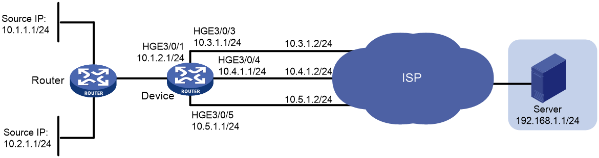
Network configuration
As shown in Figure 1, on Device, all packets destined for Server are forwarded to the next hop 10.4.1.2 by default.
Configure PBR to meet the following requirements:
· Packets with source IPv4 address 10.2.1.1 received on HundredGigE 3/0/1 are forwarded to the next hop 10.5.1.2.
· HTTP packets with source IPv4 addresses other than 10.2.1.1 received on HundredGigE 3/0/1 are forwarded to the next hop 10.3.1.2.
Analysis
To forward the two types of packets to different next hops, you must perform the following tasks:
· Configure two ACLs to classify the two types of packets.
· Configure two policy nodes to forward the packets to the specified next hops.
To ensure that packets with source address 10.2.1.1 are forwarded to the next hop 10.5.1.2, assign a node a smaller node ID to match the packets.
Software versions used
This configuration example was created and verified on Release 3606.
Restrictions and guidelines
By default, interfaces on the device are disabled (in ADM or Administratively Down state). To have an interface operate, you must use the undo shutdown command to enable that interface.
Procedures
# Configure an IPv4 address for HundredGigE 3/0/1.
<Device> system-view
[Device] interface HundredGigE 3/0/1
[Device-HundredGigE3/0/1] undo shutdown
[Device-HundredGigE3/0/1] ip address 10.1.2.1 255.255.255.0
[Device-HundredGigE3/0/1] quit
# Configure IPv4 addresses for other interfaces in the same way VLAN-interface 2 is configured. (Details not shown.)
# Configure three static routes and configure 10.4.1.2 as the default next hop.
[Device] ip route-static 192.168.1.0 24 10.3.1.2
[Device] ip route-static 192.168.1.0 24 10.4.1.2 preference 40
[Device] ip route-static 192.168.1.0 24 10.5.1.2
# Create ACL 3005 to match packets with source address 10.2.1.1.
[Device] acl advanced 3005
[Device-acl-ipv4-adv-3005] rule 0 permit ip source 10.2.1.1 0
[Device-acl-ipv4-adv-3005] quit
# Create ACL 3006 to match HTTP packets with source addresses other than 10.2.1.1.
[Device] acl advanced 3006
[Device-acl-ipv4-adv-3006] rule 0 permit tcp destination-port eq www
[Device-acl-ipv4-adv-3006] quit
# Configure Node 0 for policy pbr1 to forward packets matching ACL 3005 to the next hop 10.5.1.2.
[Device] policy-based-route pbr1 permit node 0
[Device-pbr-pbr1-0] if-match acl 3005
[Device-pbr-pbr1-0] apply next-hop 10.5.1.2
[Device-pbr-pbr1-0] quit
# Configure Node 1 for policy pbr1 to forward packets matching ACL 3006 to the next hop 10.3.1.2.
[Device] policy-based-route pbr1 permit node 1
[Device-pbr-pbr1-1] if-match acl 3006
[Device-pbr-pbr1-1] apply next-hop 10.3.1.2
[Device-pbr-pbr1-1] quit
# Apply policy pbr1 to HundredGigE 3/0/1.
[Device] interface HundredGigE 3/0/1
[Device-HundredGigE3/0/1] ip policy-based-route pbr1
[Device-HundredGigE3/0/1] quit
Verifying the configuration
# On Device, display PBR policy information.
[Device] display ip policy-based-route policy pbr1
Policy name: pbr1
node 0 permit:
if-match acl 3005
apply next-hop 10.5.1.2
node 1 permit:
if-match acl 3006
apply next-hop 10.3.1.2
The output shows that the PBR configurations are successful.
# On Switch, display the path for forwarding non-HTTP packets with source address 10.1.1.1.
|
|
NOTE: Before you use a tracert command, perform the following tasks: · Enable sending of ICMP timeout packets on the intermediate devices. · Enable sending of ICMP destination unreachable packets on the destination device. |
<Router> tracert -a 10.1.1.1 192.168.1.1
traceroute to 192.168.1.1 (192.168.1.1) from 10.1.1.1, 30 hops at most, 52 bytes
each packet, press CTRL_C to break
1 10.1.2.1 (10.1.2.1) 2.178 ms 1.364 ms 1.058 ms
2 10.4.1.2 (10.4.1.2) 1.548 ms 1.248 ms 1.112 ms
3 192.168.1.1 (192.168.1.1) 1.594 ms 1.321 ms 1.093 ms
The output shows that non-HTTP packets with source address 10.1.1.1 are forwarded to the next hop 10.4.1.2.
# On Switch, display the path for forwarding packets with source address 10.2.1.1.
<Router> tracert -a 10.2.1.1 192.168.1.1
traceroute to 192.168.1.1 (192.168.1.1) from 10.2.1.1, 30 hops at most, 40 bytes
each packet, press CTRL+C to break
1 10.1.2.1 (10.1.2.1) 1.721 ms 1.226 ms 1.050 ms
2 10.5.1.2 (10.5.1.2) 4.494 ms 1.385 ms 1.170 ms
3 192.168.1.1 (192.168.1.1) 1.448 ms 1.304 ms 1.093 ms
The output shows that packets with source address 10.2.1.1 are forwarded to the next hop 10.5.1.2.
Configuration files
#
policy-based-route pbr1 permit node 0
if-match acl 3005
apply next-hop 10.5.1.2
#
policy-based-route pbr1 permit node 1
if-match acl 3006
apply next-hop 10.3.1.2
#
interface HundredGigE3/0/1
port link-mode route
ip address 10.1.2.1 255.255.255.0
ip policy-based-route pbr1
#
interface HundredGigE3/0/3
port link-mode route
ip address 10.3.1.1 255.255.255.0
#
interface HundredGigE3/0/4
port link-mode route
ip address 10.4.1.1 255.255.255.0
#
interface HundredGigE3/0/5
port link-mode route
ip address 10.5.1.1 255.255.255.0
#
ip route-static 192.168.1.0 24 10.3.1.2
ip route-static 192.168.1.0 24 10.4.1.2 preference 40
ip route-static 192.168.1.0 24 10.5.1.2
#
acl number 3005
rule 0 permit ip source 10.2.1.1 0
#
acl number 3006
rule 0 permit tcp destination-port eq www
#
Related documentation
· H3C S12500R Switch Router Series Layer 3—IP Routing Command Reference-R3606
· H3C S12500R Switch Router Series Layer 3—IP Routing Configuration Guide-R3606
