- Table of Contents
-
- H3C WX3000 Series Unified Switches Switching Engine Configuration Guide-6W103
- 00-Preface
- 01-CLI Configuration
- 02-Login Configuration
- 03-Configuration File Management Configuration
- 04-VLAN Configuration
- 05-Auto Detect Configuration
- 06-Voice VLAN Configuration
- 07-GVRP Configuration
- 08-Basic Port Configuration
- 09-Link Aggregation Configuration
- 10-Port Isolation Configuration
- 11-Port Security-Port Binding Configuration
- 12-DLDP Configuration
- 13-MAC Address Table Management Configuration
- 14-MSTP Configuration
- 15-802.1x and System Guard Configuration
- 16-AAA Configuration
- 17-MAC Address Authentication Configuration
- 18-IP Address and Performance Configuration
- 19-DHCP Configuration
- 20-ACL Configuration
- 21-QoS-QoS Profile Configuration
- 22-Mirroring Configuration
- 23-ARP Configuration
- 24-SNMP-RMON Configuration
- 25-Multicast Configuration
- 26-NTP Configuration
- 27-SSH Configuration
- 28-File System Management Configuration
- 29-FTP-SFTP-TFTP Configuration
- 30-Information Center Configuration
- 31-System Maintenance and Debugging Configuration
- 32-VLAN-VPN Configuration
- 33-HWPing Configuration
- 34-DNS Configuration
- 35-Smart Link-Monitor Link Configuration
- 36-PoE-PoE Profile Configuration
- 37-Routing Protocol Configuration
- 38-UDP Helper Configuration
- 39-Acronyms
- 40-Index
- Related Documents
-
| Title | Size | Download |
|---|---|---|
| 37-Routing Protocol Configuration | 311.55 KB |
Table of Contents
1 IP Routing Protocol Overview
Introduction to IP Route and Routing Table
Static Routing and Dynamic Routing
Classification of Dynamic Routing Protocols
Routing Protocols and Routing Priority
Displaying and Maintaining a Routing Table
Displaying and Maintaining Static Routes
Static Route Configuration Example
Troubleshooting a Static Route
Configuring Basic RIP Functions
RIP Network Adjustment and Optimization
Displaying and Maintaining RIP Configuration
Troubleshooting RIP Configuration
4 IP Route Policy Configuration
Introduction to IP Route Policy
IP Route Policy Configuration Task List
Defining if-match Clauses and apply Clauses
Displaying and Maintaining IP Route Policy
IP Route Policy Configuration Example
Controlling RIP Packet Cost to Implement Dynamic Route Backup
Troubleshooting IP Route Policy
Go to these sections for information you are interested in:
l Introduction to IP Route and Routing Table
l Displaying and Maintaining a Routing Table
![]()
The term router in this chapter refers to a router in a generic sense or a WX3000 series device running a routing protocol.
Introduction to IP Route and Routing Table
IP Route
Routers are used for route selection on the Internet. As a router receives a packet, it selects an appropriate route (through a network) according to the destination address of the packet and forwards the packet to the next router. The last router on the route is responsible for delivering the packet to the destination host.
Routing Table
Function
The key for a router to forward packets is the routing table. Each router maintains a routing table. Each entry in this table contains an IP address that represents a host/subnet and specifies which physical port on the router should be used to forward the packets destined for the host/subnet. And the router forwards those packets through this port to the next router or directly to the destination host if the host is on a network directly connected to the router.
Routes in a routing table can be divided into three categories by origin:
l Direct routes: Routes discovered by data link protocols, also known as interface routes.
l Static routes: Routes that are manually configured.
l Dynamic routes: Routes that are discovered dynamically by routing protocols.
Routing entry
Each routing entry in a routing table contains:
l Destination: It identifies the address of the destination host or network of an IP packet.
l Mask: Along with the destination address, it identifies the address of the network segment where the destination host or router resides. By performing a logical AND operation between destination address and network mask, you can get the address of the network segment where the destination host or router resides. For example, if the destination address is 129.102.8.10 and the mask is 255.255.0.0, the address of the network segment where the destination host or router resides is 129.102.0.0. A mask consists of some consecutive 1s, represented either in dotted decimal notation or by the number of the consecutive 1s in the mask.
l Interface: It indicates through which interface IP packets should be forwarded to the destination.
l Nexthop: It indicates the next router that IP packets will pass through to reach the destination.
l Preference: There may be multiple routes with different next hops to the same destination. These routes may be discovered by different routing protocols, or be manually configured static routes. The one with the highest preference (the smallest numerical value) will be selected as the current optimal route.
According to different destinations, routes fall into the following categories:
l Subnet route: The destination is a subnet.
l Host route: The destination is a host.
In addition, according to whether the network where the destination resides is directly connected to the router, routes fall into the following categories:
l Direct route: The router is directly connected to the network where the destination resides.
l Indirect route: The router is not directly connected to the network where the destination resides.
In order to avoid an oversized routing table, you can set a default route. All the packets for which the router fails to find a matching entry in the routing table will be forwarded through this default route.
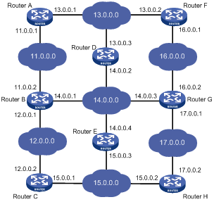
Figure 1-1 shows a relatively complicated internet environment, the number in each network cloud indicate the network address. Router G is connected to three networks, and so it has three IP addresses and three physical ports. Its routing table is shown in Figure 1-1.
|
Destination Network |
Nexthop |
Interface |
|
11.0.0.0 |
14.0.0.1 |
3 |
|
12.0.0.0 |
14.0.0.1 |
3 |
|
13.0.0.0 |
16.0.0.1 |
2 |
|
14.0.0.0 |
14.0.0.3 |
3 |
|
15.0.0.0 |
17.0.0.2 |
1 |
|
16.0.0.0 |
16.0.0.2 |
2 |
|
17.0.0.0 |
17.0.0.1 |
1 |
Routing Protocol Overview
Static Routing and Dynamic Routing
Static routing is easy to configure and requires less system resources. It works well in small, stable networks with simple topologies. It cannot adapt itself to any network topology change automatically so that you must perform routing configuration again whenever the network topology changes.
Dynamic routing is based on dynamic routing protocols, which can detect network topology changes and recalculate the routes accordingly. Therefore, dynamic routing is suitable for large networks. It is complicated to configure, and it not only imposes higher requirements on the system than static routing, but also occupies a certain amount of network resources.
Classification of Dynamic Routing Protocols
Dynamic routing protocols can be classified based on the following standards:
Operational scope
l Interior Gateway Protocols (IGPs): Work within an autonomous system, typically including RIP, OSPF, and IS-IS.
l Exterior Gateway Protocols (EGPs): Work between autonomous systems. The most popular one is BGP.
![]()
An autonomous system refers to a group of routers that share the same route policy and work under the same administration.
Routing algorithm
l Distance-vector protocols: RIP and BGP. BGP is also considered a path-vector protocol.
l Link-state protocols: OSPF and IS-IS.
The main differences between the above two types of routing algorithms lie in the way routes are discovered and calculated.
Type of the destination address
l Unicast routing protocols: RIP, OSPF, BGP, and IS-IS.
l Multicast routing protocols: PIM-SM and PIM-DM.
This chapter focuses on unicast routing protocols. For information on multicast routing protocols, refer to Multicast in H3C WX3000 Series Unified Switches Switching Engine Configuration Guide.
Routing Protocols and Routing Priority
The following table lists some routing protocols and the default priorities for routes found by them:
Table 1-1 Routing protocols and priorities of their default route
|
Routing approach |
Priority |
|
DIRECT |
0 |
|
OSPF |
10 |
|
STATIC |
60 |
|
RIP |
100 |
|
OSPF ASE |
150 |
|
OSPF NSSA |
150 |
|
UNKNOWN |
255 |
![]()
l The smaller the priority value, the higher the priority.
l The priority for a direct route is always 0, which you cannot change. Any other type of routes can have their priorities manually configured.
l Each static route can be configured with a different priority.
Load Sharing and Route Backup
Load sharing
A given routing protocol may find several routes with the same metric to the same destination, and if this protocol has the highest priority among all the active protocols, these routes will be considered valid and are used to forward packets, thus achieving load sharing.
Route backup
You can configure multiple routes to the same destination, expecting the one with the highest priority to be the primary route and all the rest backup routes.
Route backup can help improve network reliability. Automatic switching can happen between the primary route and a backup route.
Under normal circumstances, packets are forwarded through the primary route. When the primary route goes down, the route with the highest priority among the backup routes is selected to forward packets. When the primary route recovers, the route selection process is performed again and the primary route is selected again to forward packets.
Routing Information Sharing
As different routing protocols use different algorithms to calculate routes, they may discover different routes. In a large network with multiple routing protocols, it is required for routing protocols to share their routing information. Each routing protocol shares routing information discovered by other routing protocols through a route redistribution mechanism.
Displaying and Maintaining a Routing Table
|
To do… |
Use the command… |
Remarks |
|
Display brief information about a routing table |
display ip routing-table [ | { begin | exclude | include } regular-expression ] |
Available in any view |
|
Display detailed information about a routing table |
display ip routing-table verbose |
|
|
Display information about routes permitted by a basic ACL |
display ip routing-table acl acl-number [ verbose ] |
|
|
Display information about routes permitted by a prefix list |
display ip routing-table ip-prefix ip-prefix-name [ verbose ] |
|
|
Display routes to a specified destination |
display ip routing-table ip-address [ mask | mask-length ] [ longer-match ] [ verbose ] |
|
|
Display routes to specified destinations |
display ip routing-table ip-address1 { mask1 | mask-length1 } ip-address2 { mask2 | mask-length2 } [ verbose ] |
|
|
Display routes discovered by a routing protocol |
display ip routing-table protocol protocol [ inactive | verbose ] |
|
|
Display the tree-structured routing table information |
display ip routing-table radix |
|
|
Display statistics about a routing table |
display ip routing-table statistics |
|
|
Clear statistics about a routing table |
reset ip routing-table statistics protocol { all | protocol } |
Available in user view |
When configuring a static route, go to these sections for information you are interested in:
l Introduction to Static Route
l Displaying and Maintaining Static Routes
l Static Route Configuration Example
l Troubleshooting a Static Route
![]()
The term router in this chapter refers to a router in a generic sense or a WX3000 series device running a routing protocol.
Introduction to Static Route
Static Route
Static routes are special routes. They are manually configured by the administrator. In a relatively simple network, you only need to configure static routes to make routers work normally. Proper configuration and usage of static routes can improve network performance and ensure sufficient bandwidth for important applications.
When the network topology changes, static routes may become unreachable because they cannot adapt themselves to the change automatically, thus resulting in network interruption. In this case, the network administrator needs to modify the configuration of static routes manually.
Static routes are divided into three types:
l Reachable route: normal route. If a static route to a destination is of this type, the IP packets destined for this destination will be forwarded to the next hop. It is the most common type of static routes.
l Unreachable route: route with the reject attribute. If a static route to a destination has the reject attribute, all the IP packets destined for this destination will be discarded, and the source hosts will be informed of the unreachability of the destination.
l Blackhole route: route with blackhole attribute. If a static route destined for a destination has the blackhole attribute, the outgoing interface of this route is the Null 0 interface regardless of the next hop address, and all the IP packets addressed to this destination will be dropped without notifying the source hosts.
The attributes reject and blackhole are usually used to limit the range of the destinations this router can reach, and help troubleshoot the network.
Default Route
To avoid too large a routing table, you can configure a default route.
When the destination address of a packet fails to match any entry in the routing table,
l If there is default route in the routing table, the default route will be selected to forward the packet.
l If there is no default route, the packet will be discarded and an ICMP Destination Unreachable or Network Unreachable packet will be returned to the source.
A default route can be manually configured or generated by some dynamic routing protocols, such as OSPF and RIP.
Static Route Configuration
Configuration Prerequisites
Before configuring a static route, perform the following tasks:
l Configuring the physical parameters of related interfaces
l Configuring IP addresses for related interfaces
Configuring a Static Route
Follow these steps to configure a static route:
|
To do... |
Use the command... |
Remarks |
|
Enter system view |
system-view |
— |
|
Configure a static route |
ip route-static ip-address { mask | mask-length } { interface-type interface-number | next-hop } [ preference preference-value ] [ reject | blackhole ] [ detect-group group number ] [ description text ] |
Required By default, the system can obtain the route to the subnet directly connected to the router. |
![]()
l Use the ip route-static command to configure a default route by setting the destination IP address and the mask to 0.0.0.0.
l Avoid configuring the next hop address of a static route to the address of an interface on the local device.
l Different preferences can be configured to implement flexible route management policies.
l For automatic detection information, refer to Auto Detect in H3C WX3000 Series Unified Switches Switching Engine Configuration Guide.
Displaying and Maintaining Static Routes
|
To do... |
Use the command... |
Remarks |
|
Display the current configuration information |
display current-configuration |
Available in any view |
|
Display the brief information of a routing table |
display ip routing-table |
|
|
Display the detailed information of a routing table |
display ip routing-table verbose |
|
|
Display the information of static routes |
display ip routing-table protocol static [ inactive | verbose ] |
|
|
Delete all static routes |
delete static-routes all |
Available in system view |
Static Route Configuration Example
Network requirements
In this case, static routes can implement communication between any two nodes.
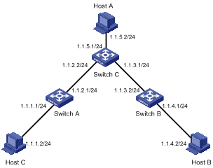
According to the network requirements, the network topology is designed as shown in Figure 2-1.
Figure 2-1 Network diagram for static route configuration
Configuration procedure
![]()
When only one interface of the device is interconnected with another network segment, you can implement network communication by configuring either a static route or default route.
1) Perform the following configurations on the device.
# Approach 1: Configure static routes on Switch A.
<SwitchA> system-view
[SwitchA] ip route-static 1.1.3.0 255.255.255.0 1.1.2.2
[SwitchA] ip route-static 1.1.4.0 255.255.255.0 1.1.2.2
[SwitchA] ip route-static 1.1.5.0 255.255.255.0 1.1.2.2
# Approach 2: Configure a static route on Switch A.
<SwitchA> system-view
[SwitchA] ip route-static 0.0.0.0 0.0.0.0 1.1.2.2
# Approach 1: Configure static routes on Switch B.
<SwitchB> system-view
[SwitchB] ip route-static 1.1.2.0 255.255.255.0 1.1.3.1
[SwitchB] ip route-static 1.1.5.0 255.255.255.0 1.1.3.1
[SwitchB] ip route-static 1.1.1.0 255.255.255.0 1.1.3.1
# Approach 2: Configure a static route on Switch B.
<SwitchB> system-view
[SwitchB] ip route-static 0.0.0.0 0.0.0.0 1.1.3.1
# Configure static routes on Switch C.
<SwitchC> system-view
[SwitchC] ip route-static 1.1.1.0 255.255.255.0 1.1.2.1
[SwitchC] ip route-static 1.1.4.0 255.255.255.0 1.1.3.2
2) Perform the following configurations on the host.
# Set the default gateway address of Host A to 1.1.5.1. Detailed configuration procedure is omitted.
# Set the default gateway address of Host B to 1.1.4.1. Detailed configuration procedure is omitted.
# Set the default gateway address of Host C to 1.1.1.1. Detailed configuration procedure is omitted.
Now, all the hosts and devices in the figure can communicate with each other.
Troubleshooting a Static Route
Symptom: The device is not configured with a dynamic routing protocol. Both the physical status and the link layer protocol status of an interface are up, but IP packets cannot be forwarded on the interface.
Solution: Perform the following procedure.
1) Use the display ip routing-table protocol static command to view whether the corresponding static route is correctly configured.
2) Use the display ip routing-table command to view whether the static route is valid.
When configuring RIP, go to these sections for information you are interested in:
l Troubleshooting RIP Configuration
![]()
The term router in this chapter refers to a router in a generic sense or a WX3000 series device running a routing protocol.
RIP Overview
Routing information protocol (RIP) is a simple interior gateway protocol (IGP) suitable for small-sized networks. RIP is not recommended in complicated large networks.
Basic Concepts
RIP
RIP is a distance-vector (D-V) algorithm–based protocol. It uses port 520 to exchange routing information through UDP packets.
RIP uses hop count (also called routing cost) to measure the distance to a destination address. In RIP, the hop count from a router to its directly connected network is 0, and that to a network which can be reached through another router is 1, and so on. To restrict the time to converge, RIP prescribes that the cost is an integer ranging from 0 and 15. The hop count equal to or exceeding 16 is defined as infinite; that is, the destination network or host is unreachable. This limitation makes RIP not suitable for large networks.
To improve performance and avoid routing loop, RIP supports split horizon. Besides, RIP can import routes discovered by other routing protocols.
RIP routing database
Each RIP router has a routing table containing routing entries of all reachable destinations, and each routing entry contains:
l Destination address: IP address of a host or network.
l Next hop: IP address of an interface on the adjacent router that IP packets should pass through to reach the destination.
l Interface: Outbound interface on this router, through which IP packets should be forwarded to reach the destination.
l Metric: Cost from the local router to the destination.
l Route time: Time elapsed since the routing entry was last updated. The time is reset to 0 every time the routing entry is updated.
RIP timers
As defined in RFC 1058, RIP is controlled by three timers: Period update, Timeout, and Garbage-collection.
l Period update timer: The period update timer defines the interval between routing updates.
l Timeout timer: The timeout timer defines the route aging time. If no update for a route is received after the aging time elapses, the metric of the route is set to 16 in the routing table.
Routing loops prevention
RIP is a distance-vector (D-V) based routing protocol. Since a RIP router advertises its own routing table to neighbors, routing loops may occur.
RIP uses the following mechanisms to prevent routing loops.
l Counting to infinity. The metric value of 16 is defined as unreachable. When a routing loop occurs, the metric value of the route will increment to 16.
l Split horizon. A router does not send the routing information learned from a neighbor back to the neighbor to prevent routing loops and save the bandwidth.
RIP Startup and Operation
The whole process of RIP startup and operation is as follows:
l Once RIP is enabled on a router, the router broadcasts or multicasts a request packet to its neighbors. Upon receiving the packet, each neighbor running RIP answers a response packet containing its routing table information.
l When this router receives a response packet, it updates its local routing table and sends a triggered update packet to the neighbors. Upon receiving the triggered update packet, the neighbor sends the packet to all its neighbors. After a series of update triggering processes, each router can get and keep the updated routing information.
l By default, RIP sends its routing table to its neighbors every 30 seconds. Upon receiving the packets, the neighbors maintain their own routing tables and select optimal routes, and then advertise update information to their respective neighbors so as to make the updated routes known globally. Furthermore, RIP uses the aging mechanism to handle the timeout routes to ensure real-time and valid routes.
RIP Configuration Task List
Complete the following tasks to configure RIP:
|
Task |
Remarks |
|
|
Enabling RIP on the interfaces attached to a specified network segment |
Required |
|
|
Optional |
||
|
Optional |
||
|
Optional |
||
|
Optional |
||
|
Optional |
||
|
Optional |
||
|
Optional |
||
|
Configuring RIP to redistribute routes from another protocol |
Optional |
|
|
Optional |
||
|
Optional |
||
|
Optional |
||
|
Optional |
||
|
Optional |
||
Basic RIP Configuration
Configuration Prerequisites
Before configuring basic RIP functions, perform the following tasks:
l Configuring the link layer protocol
Configuring Basic RIP Functions
Enabling RIP on the interfaces attached to a specified network segment
Follow these steps to enable RIP on the interfaces attached to a specified network segment:
|
To do... |
Use the command... |
Remarks |
|
Enter system view |
system-view |
— |
|
Enable RIP and enter RIP view |
rip |
Required |
|
Enable RIP on the specified interface |
network network-address |
Required Disabled by default |
![]()
l Related RIP commands configured in interface view can take effect only after RIP is enabled.
Setting the RIP operating status on an interface
Follow these steps to set the RIP operating status on an interface:
|
To do... |
Use the command... |
Remarks |
|
Enter system view |
system-view |
— |
|
Enter interface view |
interface interface-type interface-number |
— |
|
Enable the interface to receive RIP update packets |
rip input |
Optional Enabled by default |
|
Enable the interface to send RIP update packets |
rip output |
|
|
Enable the interface to receive and send RIP update packets |
rip work |
Specifying the RIP version on an interface
Follow these steps to specify the RIP version on an interface:
|
To do... |
Use the command... |
Remarks |
|
Enter system view |
system-view |
— |
|
Enter interface view |
interface interface-type interface-number |
— |
|
Specify the version of the RIP running on the interface |
rip version { 1 | 2 [ broadcast | multicast ] } |
Optional By default, the version of the RIP running on an interface is RIP-1. |
RIP Route Control
In actual implementation, it may be needed to control RIP routing information more accurately to accommodate complex network environments. By performing the configuration described in the following sections, you can:
l Control route selection by adjusting additional routing metrics on interfaces running RIP.
l Reduce the size of the routing table by setting route summarization and disabling the receiving of host routes.
l Filter incoming and outgoing routes.
l Redistribute external routes in an environment with multiple routing protocols.
Configuration Prerequisites
Before configuring RIP route control, perform the following tasks:
l Configuring network layer addresses of interfaces so that adjacent nodes are reachable to each other at the network layer
l Configuring basic RIP functions
Configuring RIP Route Control
Setting the additional routing metrics of an interface
Additional metric is the metric added to the original metrics of RIP routes on an interface. It does not directly change the metric value of a RIP route in the routing table of a router, but will be added to incoming or outgoing RIP routes on the interface.
Follow these steps to set additional routing metric:
|
To do... |
Use the command... |
Remarks |
|
Enter system view |
system-view |
— |
|
Enter interface view |
interface interface-type interface-number |
— |
|
Set the additional routing metric to be added for incoming RIP routes on this interface |
rip metricin value |
Optional 0 by default |
|
Set the additional routing metric to be added for outgoing RIP routes on this interface |
rip metricout value |
Optional 1 by default |
![]()
The rip metricout command takes effect only on the RIP routes learnt by the router and the RIP routes generated by the router itself, but the command is invalid for any route imported to RIP from other routing protocols.
Configuring RIP route summarization
Rip route summarization means that when the router advertises RIP updates, different subnet routes in the same natural network segment can be aggregated into one route with a natural mask for transmission to another network segment. This function is used to reduce the routing traffic on the network as well as the size of the routing table.
When it is necessary to advertise RIP route updates in a subnet, disable the route summarization for RIP-2.
Follow these steps to configure RIP route summarization:
|
To do... |
Use the command... |
Remarks |
|
Enter system view |
system-view |
— |
|
Enter RIP view |
rip |
— |
|
Enable RIP-2 automatic route summarization |
summary |
Required Enabled by default |
Disabling the router from receiving host routes
In some special cases, the router can receive a lot of host routes from the same segment, and these routes are of little help in route addressing but consume a lot of network resources. After a router is disabled from receiving host routes, it can refuse any incoming host route.
Follow these steps to disable the router from receiving host routes:
|
To do... |
Use the command... |
Remarks |
|
Enter system view |
system-view |
— |
|
Enter RIP view |
rip |
— |
|
Disable the router from receiving host routes |
undo host-route |
Required By default, the router receives host routes. |
Configuring RIP to filter incoming/outgoing routes
The route filtering function provided by a router enables you to configure inbound/outbound filter policy by specifying an ACL, address prefix list, or route policy to make RIP filter incoming/outgoing routes. Besides, you can configure RIP to receive only the RIP packets from a specific neighbor.
Follow these steps to configure RIP to filter incoming/outgoing routes:
|
To do... |
Use the command... |
Remarks |
|
Enter system view |
system-view |
— |
|
Enter RIP view |
rip |
— |
|
Configure RIP to filter incoming routes |
filter-policy { acl-number | route-policy route-policy-name } import |
Required By default, RIP does not filter any incoming route. |
|
filter-policy gateway ip-prefix-name import |
||
|
Configure RIP to filter outgoing routes |
filter-policy acl-number export [ protocol [ process-id ] ] |
Required By default, RIP does not filter any outgoing route. |
|
filter-policy route-policy route-policy-name export |
![]()
l The filter-policy import command filters the RIP routes received from neighbors, and the routes being filtered out will neither be added to the routing table nor be advertised to any neighbors.
l The filter-policy export command filters all the routes to be advertised, including the routes redistributed with the import-route command and routes learned from neighbors.
l You can also use the filter-policy export command to filter outgoing routes redistributed from a specified routing protocol.
Setting RIP preference
Follow these steps to set RIP preference:
|
To do... |
Use the command... |
Remarks |
|
Enter system view |
system-view |
— |
|
Enter RIP view |
rip |
— |
|
Set the RIP preference |
preference value |
Required 100 by default |
Configuring RIP to redistribute routes from another protocol
Follow these steps to configure RIP to import routes from another protocol:
|
To do... |
Use the command... |
Remarks |
|
Enter system view |
system-view |
— |
|
Enter RIP view |
rip |
— |
|
Configure a default cost for an incoming route |
default cost value |
Optional 1 by default |
|
Configure RIP to redistribute routes from another protocol |
import-route protocol [ process-id ] [ cost value | route-policy route-policy-name ]* |
Required By default, RIP does not redistribute any route from other protocols. |
RIP Network Adjustment and Optimization
In some special network environments, some RIP features need to be configured and RIP network performance needs to be adjusted and optimized. By performing the configuration mentioned in this section, the following can be implemented:
l Changing the convergence speed of RIP network by adjusting RIP timers;
l Avoiding routing loops by configuring split horizon;
l Packet validation in network environments with high security requirements, and
l Configuring RIP to unicast RIP messages on interfaces with special requirements.
Configuration Prerequisites
Before adjusting RIP, perform the following tasks:
l Configuring the network layer addresses of interfaces so that adjacent nodes are reachable to each other at the network layer
l Configuring basic RIP functions
Configuration Tasks
Configuring RIP timers
Follow these steps to configure RIP timers:
|
To do... |
Use the command... |
Remarks |
|
Enter system view |
system-view |
— |
|
Enter RIP view |
rip |
— |
|
Set the RIP timers |
timers { update update-timer | timeout timeout-timer } * |
Required By default, the Update timer is 30 seconds and the Timeout timer 180 seconds. |
![]()
When configuring the values of RIP timers, you should take network performance into consideration and perform consistent configuration on all routers running RIP to avoid unnecessary network traffic and network route oscillation.
Configuring split horizon
Follow these steps to configure split horizon:
|
To do... |
Use the command... |
Remarks |
|
Enter system view |
system-view |
— |
|
Enter interface view |
interface interface-type interface-number |
— |
|
Enable split horizon |
rip split-horizon |
Required Enabled by default |
Split horizon cannot be disabled on a point-to-point link.
Configuring RIP-1 packet zero field check
Follow these steps to configure RIP-1 packet zero field check:
|
To do... |
Use the command... |
Remarks |
|
Enter system view |
system-view |
— |
|
Enter RIP view |
rip |
— |
|
Enable the check of the must be zero field in RIP-1 packets |
checkzero |
Required Enabled by default |
![]()
Some fields in a RIP-1 packet must be 0, and they are known as must be zero field. For RIP-1, the must be zero field is checked for incoming packets, and those RIP-1 packets with this field being nonzero will not be processed.
Setting RIP-2 packet authentication mode
RIP-2 supports two authentication modes: simple authentication and message digest 5 (MD5) authentication.
Simple authentication cannot provide complete security, because the authentication keys sent along with packets that are not encrypted. Therefore, simple authentication cannot be applied where high security is required.
Follow these steps to set RIP-2 packet authentication mode:
|
To do... |
Use the command... |
Remarks |
|
Enter system view |
system-view |
— |
|
Enter interface view |
interface interface-type interface-number |
— |
|
Set RIP-2 packet authentication mode |
rip authentication-mode { simple password | md5 { rfc2082 key-string key-id | rfc2453 key-string } } |
Required If you specify to use MD5 authentication, you must specify one of the following MD5 authentication types: l rfc2453 (this type supports the packet format defined in RFC 2453) l rfc2082 (this type supports the packet format defined in RFC 2082) |
Configuring RIP to unicast RIP packets
Follow these steps to configure RIP to unicast RIP packets:
|
To do... |
Use the command... |
Remarks |
|
Enter system view |
system-view |
— |
|
Enter RIP view |
rip |
— |
|
Configure RIP to unicast RIP packets |
peer ip-address |
Required When RIP runs on the link that does not support broadcast or multicast, you must configure RIP to unicast RIP packets. |
Displaying and Maintaining RIP Configuration
|
To do... |
Use the command... |
Remarks |
|
Display the current RIP running status and configuration information |
display rip |
Available in any view |
|
Display RIP interface information |
display rip interface |
|
|
Display RIP routing information |
display rip routing |
|
|
Reset the system configuration related to RIP |
reset |
Available in RIP view |
RIP Configuration Example
Network requirements
A small-sized company requires that any two nodes in its small office network communicate with each other, and that the network devices automatically adapt themselves to any topology change so as to reduce the work of manual maintenance.
In this case, RIP can implement communication between any two nodes.
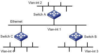
According to the network requirements, the network topology is designed as shown in Figure 3-1.
Figure 3-1 Network diagram for RIP configuration
|
Device |
Interface |
IP address |
Device |
Interface |
IP address |
|
Switch A |
Vlan-int1 |
110.11.2.1/24 |
Switch B |
Vlan-int1 |
110.11.2.2/24 |
|
|
Vlan-int2 |
155.10.1.1/24 |
|
Vlan-int3 |
196.38.165.1/24 |
|
Switch C |
Vlan-int1 |
110.11.2.3/24 |
|
|
|
|
|
Vlan-int4 |
117.102.0.1/16 |
|
|
|
Configuration procedure
![]()
Only the configuration related to RIP is listed below. Before the following configuration, make sure the Ethernet link layer works normally and the IP addresses of VLAN interfaces are configured correctly.
1) Configure Switch A:
# Configure RIP.
<SwitchA> system-view
[SwitchA] rip
[SwitchA-rip] network 110.11.2.0
[SwitchA-rip] network 155.10.1.0
2) Configure Switch B:
# Configure RIP.
<SwitchB> system-view
[SwitchB] rip
[SwitchB-rip] network 196.38.165.0
[SwitchB-rip] network 110.11.2.0
3) Configure Switch C:
# Configure RIP.
<SwitchC> system-view
[SwitchC] rip
[SwitchC-rip] network 117.102.0.0
[SwitchC-rip] network 110.11.2.0
Troubleshooting RIP Configuration
Failed to Receive RIP Updates
Symptom
The device cannot receive any RIP update when the physical connection between the device and the peer routing device is normal.
Solution
Check that:
l RIP is enabled by using the network command on the corresponding interface.
l The interface is allowed to receive or send RIP packets.
l The interface receives RIP packets in the way the peer device sends them, for example, in the broadcast or multicast mode.
When configuring an IP route policy, go to these sections for information you are interested in:
l IP Route Policy Configuration Task List
l Displaying and Maintaining IP Route Policy
l IP Route Policy Configuration Example
l Troubleshooting IP Route Policy
![]()
The term router in this chapter refers to a router in a generic sense or a WX3000 series device running a routing protocol.
IP Route Policy Overview
Introduction to IP Route Policy
Route policy is technology used to modify routing information to control the forwarding path of data packets. Route policy is implemented by changing the route attributes such as reachability.
When a router distributes or receives routing information, it may need to implement some policies to filter the routing information, so as to receive or distribute only the routing information meeting given conditions. A routing protocol (RIP, for example) may need to import the routing information discovered by other protocols to enrich its routing knowledge. While importing routing information from another protocol, it possibly only needs to import the routes meeting given conditions and control some attributes of the imported routes to make the routes meet the requirements of this protocol.
For the implementation of a route policy, you need to define a set of matching rules by specifying the characteristics of the routing information to be filtered. You can set the rules based on such attributes as destination address and source address of the information. The matching rules can be set in advance and then used in the routing policies to advertise, receive, and import routes.
Filters
A routing protocol can reference an ACL, IP-prefix, or route policy to filter routing information. The following sections describe these filters.
ACL
You can specify a range of IP addresses or subnets when defining an ACL so as to match the destination network addresses or next-hop addresses in routing information. You can reference an ACL into a route policy to filter routing information.
For ACL configuration, refer to ACL in H3C WX3000 Series Unified Switches Switching Engine Configuration Guide.
Route policy
A route policy is used to match some attributes with given routing information and the attributes of the information will be set if the conditions are satisfied.
A route policy can comprise multiple nodes. Each node is a unit for matching test, and the nodes will be matched in ascending order of their node numbers. Each node comprises a set of if-match and apply clauses. The if-match clauses define the matching rules. The matching objects are some attributes of routing information. The relationship among the if-match clauses for a node is “AND”. As a result, a matching test against a node is successful only when all the matching conditions specified by the if-match clauses in the node are satisfied. The apply clauses specify the actions performed after a matching test against the node is successful, and the actions can be the attribute settings of routing information.
There is an OR relationship between different nodes in a route policy. As a result, the system examines the nodes in the route policy in sequence, and once the route matches a node in the route policy, it will pass the matching test of the route policy without entering the test of the next node.
IP Route Policy Configuration Task List
Complete the following tasks to configure an IP route policy:
|
Task |
Remarks |
|
|
Required |
||
|
Required |
||
Route Policy Configuration
A route policy is used to match given routing information or some attributes of routing information and change the attributes of the routing information if the conditions are met. The above-mentioned filtering lists can serve as the match conditions:
A route policy can comprise multiple nodes and each node comprises:
l if-match clause: Defines matching rules; that is, the filtering conditions that the routing information should satisfy for passing the current route policy. The matching objects are some attributes of the routing information.
Configuration Prerequisites
Before configuring a route policy, perform the following tasks:
l Configuring a filtering list,
l Configuring a routing protocol
Prepare the following data before the configuration:
l Route policy name and node number
l Match conditions
l Route attributes to be changed
Defining a Route Policy
Follow these steps to define a route policy:
|
To do... |
Use the command... |
Remarks |
|
Enter system view |
system-view |
— |
|
Define a route policy and enter the route policy view |
route-policy route-policy-name { permit | deny } node node-number |
Required Not defined by default |
![]()
l The permit argument specifies the matching mode for a defined node in the route policy to be in permit mode. If a route matches the rules for the node, the apply clauses for the node will be executed and the test of the next node will not be taken. If not, however, the route takes the test of the next node.
l The deny argument specifies the matching mode for a defined node in the route policy to be in deny mode. In this mode, no apply clause is executed. If a route satisfies all the if-match clauses of the node, no apply clause for the node will be executed and the test of the next node will not be taken. If not, however, the route takes the test of the next node.
l If multiple nodes are defined in a route policy, at least one of them should be in permit mode. When a route policy is applied to filtering routing information, if a piece of routing information does not match any node, the routing information will be denied by the route policy. If all the nodes in the route policy are in deny mode, all routing information will be denied by the route policy.
Defining if-match Clauses and apply Clauses
Follow these steps to define if-match clauses and apply clauses:
|
To do... |
Use the command... |
Remarks |
|
Enter system view |
system-view |
— |
|
Enter the route-policy view |
route-policy route-policy-name { permit | deny } node node-number |
Required |
|
Define a rule to match the IP address of routing information |
if-match acl acl-number |
Optional By default, no matching is performed on the address of routing information. |
|
Define a rule to match the cost of routes |
if-match cost value |
Optional By default, no matching is performed against the cost of routes. |
|
Define a rule to match the next-hop interface of routing information |
if-match interface interface-type interface-number |
Optional By default, no matching is performed on the next-hop interface of routing information. |
|
Define a rule to match the next-hop address of routing information |
if-match ip next-hop acl acl-number |
Optional By default, no matching is performed on the next-hop address of routing information. |
|
Apply a cost to routes satisfying matching rules |
apply cost value |
Optional By default, no cost is applied to routes satisfying matching rules. |
![]()
l A route policy comprises multiple nodes. There is an OR relationship between the nodes in a route policy. As a result, the system examines the nodes in sequence, and once the route matches a node in the route policy, it will pass the matching test of the route policy without entering the test of the next node.
l During the matching, there is an AND relationship between the if-match clauses for a route policy node. That is, a matching test against a node is successful only when all the matching conditions specified by the if-match clauses in the node are satisfied.
l If no if-match clauses are specified, all the routes will filter through the node.
l A node can comprise no if-match clause or multiple if-match clauses.
l Each node comprises a set of if-match and apply clauses. if-match clauses define matching rules. apply clauses specify the actions performed after a matching test against the node is successful, and the actions can be the attribute settings of routing information.
Displaying and Maintaining IP Route Policy
|
To do... |
Use the command... |
Remarks |
|
Display route policy information |
display route-policy [ route-policy-name ] |
Available in any view |
IP Route Policy Configuration Example
Controlling RIP Packet Cost to Implement Dynamic Route Backup
Network requirements
The required speed of convergence in the small network of a company is not high. The network provides two services. Main and backup links are provided for each service for the purpose of reliability. The main link of one service serves as the backup link of the other. The two services are distinguished by IP addresses. If a fault occurs to the main link of one service, dynamic backup can prevent service interruption.
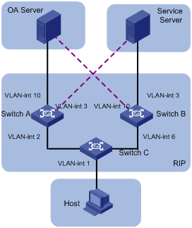
According to the network requirements, the network topology is designed as shown in Figure 4-1.
|
Device |
Interface |
IP address |
|
Switch A |
Vlan-int 2 |
2.2.2.1/8 |
|
|
Vlan-int 3 |
3.3.3.254/8 |
|
|
Vlan-int 10 |
1.1.1.254/8 |
|
Switch B |
Vlan-int 3 |
3.3.3.253/8 |
|
|
Vlan-int 6 |
6.6.6.5/8 |
|
|
Vlan-int 10 |
1.1.1.253/8 |
|
Switch C |
Vlan-int 1 |
192.168.0.39/24 |
|
|
Vlan-int 2 |
2.2.2.2/8 |
|
|
Vlan-int 6 |
6.6.6.6/8 |
|
OA Server |
|
1.1.1.1/32 |
|
Service Server |
|
3.3.3.3/32 |
|
Host |
|
192.168.0.9/24 |
Configuration considerations
l According to the network requirements, select RIP.
l For the OA server, the main link is between Switch A and Switch C, while the backup link is between Switch B and Switch C.
l For the service server, the main link is between Switch B and Switch C, while the backup link is between Switch A and Switch C.
l Apply a route policy to control the cost of routes received by Switch C to provide main and backup links for the services of the OA server and service server.
Configuration procedure
1) Configure Switch A.
# Create VLANs and configure IP addresses for the VLAN interfaces. The configuration procedure is omitted.
# Configure RIP.
<SwitchA> system-view
[SwitchA] rip
[SwitchA-rip] network 1.0.0.0
[SwitchA-rip] network 2.0.0.0
[SwitchA-rip] network 3.0.0.0
2) Configure Switch B.
# Create VLANs and configure IP addresses for the VLAN interfaces. The configuration procedure is omitted.
# Configure RIP.
<SwitchB> system-view
[SwitchB] rip
[SwitchB-rip] network 1.0.0.0
[SwitchB-rip] network 3.0.0.0
[SwitchB-rip] network 6.0.0.0
3) Configure Switch C.
# Create VLANs and configure IP addresses for the VLAN interfaces. The configuration procedure is omitted.
# Define IP-prefix 1 containing the IP address prefix 1.0.0.0/8, and IP-prefix 2 containing the IP address prefix 3.0.0.0/8.
<SwitchC> system-view
[SwitchC] acl number 2000
[SwitchC-acl-basic-2000] rule permit source 1.0.0.0 0.255.255.255
[SwitchC-acl-basic-2000] quit
[SwitchC] acl number 2001
[SwitchC-acl-basic-2000] rule permit source 3.0.0.0 0.255.255.255
[SwitchC-acl-basic-2000] quit
# Create a route policy named in and node 10 with the matching mode being permit. Define if-match clauses. Apply the cost 5 to routes matching the outgoing interface VLAN-interface 2 and ACL 2000.
[SwitchC] route-policy in permit node 10
[SwitchC-route-policy] if-match interface Vlan-interface2
[SwitchC-route-policy] if-match acl 2000
[SwitchC-route-policy] apply cost 5
[SwitchC-route-policy] quit
# Create node 20 with the matching mode being permit in the route policy. Define if-match clauses. Apply the cost 6 to routes matching the outgoing interface VLAN-interface 2 and ACL 2001.
[SwitchC] route-policy in permit node 20
[SwitchC-route-policy] if-match interface Vlan-interface2
[SwitchC-route-policy] if-match acl 2001
[SwitchC-route-policy] apply cost 6
[SwitchC-route-policy] quit
# Create node 30 with the matching mode being permit in the route policy. Define if-match clauses. Apply the cost 6 to routes matching the outgoing interface VLAN-interface 6 and ACL 2000.
[SwitchC] route-policy in permit node 30
[SwitchC-route-policy] if-match interface Vlan-interface6
[SwitchC-route-policy] if-match acl 2000
[SwitchC-route-policy] apply cost 6
[SwitchC-route-policy] quit
# Create node 40 with the matching mode being permit in the route policy. Define if-match clauses. Apply the cost 5 to routes matching the outgoing interface VLAN-interface 6 and ACL 2001.
[SwitchC] route-policy in permit node 40
[SwitchC-route-policy] if-match interface Vlan-interface6
[SwitchC-route-policy] if-match acl 2001
[SwitchC-route-policy] apply cost 5
[SwitchC-route-policy] quit
# Create node 50 with the matching mode being permit, to allow all routing information to pass.
[SwitchC] route-policy in permit node 50
[SwitchC-route-policy] quit
# Configure RIP and apply the route policy in to the incoming routing information.
[SwitchC] rip
[SwitchC-rip] network 1.0.0.0
[SwitchC-rip] network 3.0.0.0
[SwitchC-rip] network 6.0.0.0
[SwitchC-rip] filter-policy route-policy in import
Configuration verification
1) Display data forwarding paths when the main link of the OA server between Switch A and Switch C works normally.
<SwitchC> display ip routing-table
Routing Table: public net
Destination/Mask Protocol Pre Cost Nexthop Interface
1.0.0.0/8 RIP 100 5 2.2.2.1 Vlan-interface2
2.0.0.0/8 DIRECT 0 0 2.2.2.2 Vlan-interface2
2.2.2.2/32 DIRECT 0 0 127.0.0.1 InLoopBack0
3.0.0.0/8 RIP 100 5 6.6.6.5 Vlan-interface6
6.0.0.0/8 DIRECT 0 0 6.6.6.6 Vlan-interface6
6.6.6.6/32 DIRECT 0 0 127.0.0.1 InLoopBack0
127.0.0.0/8 DIRECT 0 0 127.0.0.1 InLoopBack0
127.0.0.1/32 DIRECT 0 0 127.0.0.1 InLoopBack0
192.168.0.0/24 DIRECT 0 0 192.168.0.39 Vlan-interface1
192.168.0.39/32 DIRECT 0 0 127.0.0.1 InLoopBack0
2) Display data forwarding paths when the main link of the OA server between Switch A and Switch C is down.
<SwitchC> display ip routing-table
Routing Table: public net
Destination/Mask Protocol Pre Cost Nexthop Interface
1.0.0.0/8 RIP 100 6 6.6.6.5 Vlan-interface2
3.0.0.0/8 RIP 100 5 6.6.6.5 Vlan-interface6
6.0.0.0/8 DIRECT 0 0 6.6.6.6 Vlan-interface6
6.6.6.6/32 DIRECT 0 0 127.0.0.1 InLoopBack0
127.0.0.0/8 DIRECT 0 0 127.0.0.1 InLoopBack0
127.0.0.1/32 DIRECT 0 0 127.0.0.1 InLoopBack0
192.168.0.0/24 DIRECT 0 0 192.168.0.39 Vlan-interface1
192.168.0.39/32 DIRECT 0 0 127.0.0.1 InLoopBack0
Precautions
1) When you configure the apply cost command in a route policy:
l The new cost should be greater than the original one to prevent RIP from generating routing loop in the case that a loop exists in the topology.
l The cost will become 16 if you try to set it to a value greater than 16.
l The cost will become the original one if you try to set it to 0.
l The cost will still be 16 if you try to set it to 16.
2) Using the if-match interface command will match the routes whose outgoing interface to the next hop is the specified interface.
3) You are recommended to configure a node to match all routes not passing the preceding nodes in a route policy.
4) If the cost of a received RIP route is equal to 16, the cost specified by the apply cost command in a route policy will not be applied to the route, that is, the cost of the route is equal to 16.
5) Using the filter-policy command does not filter redistributed routes.
Troubleshooting IP Route Policy
Symptom
The route policy cannot filter routing information correctly when the routing protocol runs normally.
Analysis
The route policy cannot filter routing information correctly in the following two cases:
l All nodes in the route policy are in the deny mode.
l All entries in the IP-prefix list are in the deny mode.
Solution
1) Use the display ip ip-prefix command to display the configuration of the IP-prefix list.
2) Use the display route-policy command to display the configuration of the route policy.