- Table of Contents
-
- H3C WX3000 Series Unified Switches Switching Engine Configuration Guide-6W103
- 00-Preface
- 01-CLI Configuration
- 02-Login Configuration
- 03-Configuration File Management Configuration
- 04-VLAN Configuration
- 05-Auto Detect Configuration
- 06-Voice VLAN Configuration
- 07-GVRP Configuration
- 08-Basic Port Configuration
- 09-Link Aggregation Configuration
- 10-Port Isolation Configuration
- 11-Port Security-Port Binding Configuration
- 12-DLDP Configuration
- 13-MAC Address Table Management Configuration
- 14-MSTP Configuration
- 15-802.1x and System Guard Configuration
- 16-AAA Configuration
- 17-MAC Address Authentication Configuration
- 18-IP Address and Performance Configuration
- 19-DHCP Configuration
- 20-ACL Configuration
- 21-QoS-QoS Profile Configuration
- 22-Mirroring Configuration
- 23-ARP Configuration
- 24-SNMP-RMON Configuration
- 25-Multicast Configuration
- 26-NTP Configuration
- 27-SSH Configuration
- 28-File System Management Configuration
- 29-FTP-SFTP-TFTP Configuration
- 30-Information Center Configuration
- 31-System Maintenance and Debugging Configuration
- 32-VLAN-VPN Configuration
- 33-HWPing Configuration
- 34-DNS Configuration
- 35-Smart Link-Monitor Link Configuration
- 36-PoE-PoE Profile Configuration
- 37-Routing Protocol Configuration
- 38-UDP Helper Configuration
- 39-Acronyms
- 40-Index
- Related Documents
-
| Title | Size | Download |
|---|---|---|
| 10-Port Isolation Configuration | 62.35 KB |
Table of Contents
1 Port Isolation Configuration
Introduction to Port Isolation
Displaying and Maintaining Port Isolation
Port Isolation Configuration Example
![]()
l The term switch used throughout this chapter refers to a switching device in a generic sense or the switching engine of a unified switch in the WX3000 series.
l The sample output information in this manual was created on the WX3024. The output information on your device may vary.
Port Isolation Overview
Introduction to Port Isolation
Through the port isolation feature, you can add the ports to be controlled into an isolation group to isolate the Layer 2 data between each port in the isolation group. Thus, you can improve the network security and network in a more flexible way.
Currently, you can configure only one isolation group on a switch. The number of Ethernet ports an isolation group can accommodate is not limited.
![]()
The port isolation function is independent of VLAN configuration.
Port Isolation Configuration
Follow these steps to add an Ethernet port to an isolation group:
|
To do… |
Use the command… |
Remarks |
|
Enter system view |
system-view |
— |
|
Enter Ethernet port view |
interface interface-type interface-num |
— |
|
Add the Ethernet port to the isolation group |
port isolate |
Required By default, an isolation group contains no port. |
![]()
l When a member port of an aggregation group is added to an isolation group, the other ports in the same aggregation group are added to the isolation group automatically.
l When a member port of an aggregation group is deleted from an isolation group, the other ports in the same aggregation group are deleted from the isolation group automatically.
Displaying and Maintaining Port Isolation
|
To do… |
Use the command… |
Remarks |
|
Display the information about the Ethernet ports added to the isolation group. |
display isolate port |
Available in any view |
Port Isolation Configuration Example
Network requirements
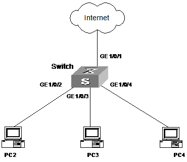
As shown in Figure 1-1:
l PC 2, PC 3 and PC 4 are connected to GigabitEthernet 1/0/2, GigabitEthernet 1/0/3, and GigabitEthernet 1/0/4.
l The switch connects to the Internet through GigabitEthernet 1/0/1.
l It is desired that PC 2, PC 3 and PC 4 cannot communicate with each other.
Figure 1-1 Network diagram for port isolation configuration
Configuration procedure
# Add GigabitEthernet 1/0/2, GigabitEthernet 1/0/3, and GigabitEthernet 1/0/4 to the isolation group.
<device> system-view
System View: return to User View with Ctrl+Z.
[device] interface GigabitEthernet1/0/2
[device-GigabitEthernet1/0/2] port isolate
[device-GigabitEthernet1/0/2] quit
[device] interface GigabitEthernet1/0/3
[device-GigabitEthernet1/0/3] port isolate
[device-GigabitEthernet1/0/3] quit
[device] interface GigabitEthernet1/0/4
[device-GigabitEthernet1/0/4] port isolate
[device-GigabitEthernet1/0/4] quit
[device]
# Display the information about the ports in the isolation group.
[device] display isolate port
Isolated port(s) on UNIT 1:
GigabitEthernet1/0/2, GigabitEthernet1/0/3, GigabitEthernet1/0/4