- Table of Contents
-
- H3C WX3000 Series Unified Switches Switching Engine Configuration Guide-6W103
- 00-Preface
- 01-CLI Configuration
- 02-Login Configuration
- 03-Configuration File Management Configuration
- 04-VLAN Configuration
- 05-Auto Detect Configuration
- 06-Voice VLAN Configuration
- 07-GVRP Configuration
- 08-Basic Port Configuration
- 09-Link Aggregation Configuration
- 10-Port Isolation Configuration
- 11-Port Security-Port Binding Configuration
- 12-DLDP Configuration
- 13-MAC Address Table Management Configuration
- 14-MSTP Configuration
- 15-802.1x and System Guard Configuration
- 16-AAA Configuration
- 17-MAC Address Authentication Configuration
- 18-IP Address and Performance Configuration
- 19-DHCP Configuration
- 20-ACL Configuration
- 21-QoS-QoS Profile Configuration
- 22-Mirroring Configuration
- 23-ARP Configuration
- 24-SNMP-RMON Configuration
- 25-Multicast Configuration
- 26-NTP Configuration
- 27-SSH Configuration
- 28-File System Management Configuration
- 29-FTP-SFTP-TFTP Configuration
- 30-Information Center Configuration
- 31-System Maintenance and Debugging Configuration
- 32-VLAN-VPN Configuration
- 33-HWPing Configuration
- 34-DNS Configuration
- 35-Smart Link-Monitor Link Configuration
- 36-PoE-PoE Profile Configuration
- 37-Routing Protocol Configuration
- 38-UDP Helper Configuration
- 39-Acronyms
- 40-Index
- Related Documents
-
| Title | Size | Download |
|---|---|---|
| 25-Multicast Configuration | 533.63 KB |
Information Transmission in the Unicast Mode
Information Transmission in the Broadcast Mode
Information Transmission in the Multicast Mode
Advantages and Applications of Multicast
Multicast Packet Forwarding Mechanism
Implementation of the RPF Mechanism
Basic Concepts in IGMP Snooping
Work Mechanism of IGMP Snooping
IGMP Snooping Configuration Task List
Configuring the Version of IGMP Snooping
Configuring Fast Leave Processing
Configuring a Multicast Group Filter
Configuring the Maximum Number of Multicast Groups on a Port
Suppressing Flooding of Unknown Multicast Traffic in a VLAN
Configuring Static Member Port for a Multicast Group
Configuring a Static Router Port
Configuring a Port as a Simulated Group Member
Configuring a VLAN Tag for Query Messages
Displaying and Maintaining IGMP Snooping
IGMP Snooping Configuration Examples
3 Common Multicast Configuration
Common Multicast Configuration
Configuring a Multicast MAC Address Entry
Configuring Dropping Unknown Multicast Packets
Displaying and Maintaining Common Multicast Configuration
![]()
l The term switch used throughout this chapter refers to a switching device in a generic sense or the switching engine of the WX3000 series devices.
l The sample output information in this manual was created on the WX3024. The output information on your device may vary.
Multicast Overview
With development of networks on the Internet, more and more interaction services such as data, voice, and video services are running on the networks. In addition, highly bandwidth- and time-critical services, such as e-commerce, Web conference, online auction, video on demand (VoD), and tele-education have come into being. These services have higher requirements for information security, legal use of paid services, and network bandwidth.
Information Transmission in the Unicast Mode
In unicast, the system establishes a separate data transmission channel for each user requiring this information, and sends a separate copy of the information to the user, as shown in Figure 1-1:
Figure 1-1 Information transmission in the unicast mode
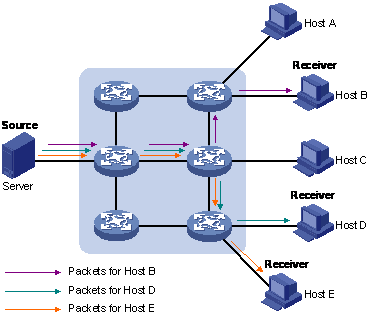
Assume that Hosts B, D and E need this information. The source server establishes transmission channels for the devices of these users respectively. As the transmitted traffic over the network is in direct proportion to the number of users that receive this information, when a large number of users need this information, the server must send many pieces of information with the same content to the users. Therefore, the limited bandwidth becomes the bottleneck in information transmission. This shows that unicast is not good for the transmission of a great deal of information.
Information Transmission in the Broadcast Mode
When you adopt broadcast, the system transmits information to all users on a network. Any user on the network can receive the information, no matter the information is needed or not. Figure 1-2shows information transmission in broadcast mode.
Figure 1-2 Information transmission in the broadcast mode
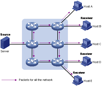
Assume that Hosts B, D, and E need the information. The source server broadcasts this information through routers, and Hosts A and C on the network also receive this information.
As we can see from the information transmission process, the security and legal use of paid service cannot be guaranteed. In addition, when only a small number of users on the same network need the information, the utilization ratio of the network resources is very low and the bandwidth resources are greatly wasted.
Information Transmission in the Multicast Mode
As described in the previous sections, unicast is suitable for networks with sparsely distributed users, whereas broadcast is suitable for networks with densely distributed users. When the number of users requiring information is not certain, unicast and broadcast deliver a low efficiency.
Multicast solves this problem. When some users on a network require specified information, the multicast information sender (namely, the multicast source) sends the information only once. With multicast distribution trees established for multicast data packets through multicast routing protocols, the packets are duplicated and distributed at the nearest nodes, as shown in Figure 1-3:
Figure 1-3 Information transmission in the multicast mode
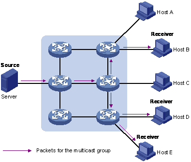
Assume that Hosts B, D and E need the information. To transmit the information to the right users, it is necessary to group Hosts B, D and E into a receiver set. The routers on the network duplicate and distribute the information based on the distribution of the receivers in this set. Finally, the information is correctly delivered to Hosts B, D, and E.
The advantages of multicast over unicast are as follows:
l No matter how many receivers exist, there is only one copy of the same multicast data flow on each link.
l With the multicast mode used to transmit information, an increase of the number of users does not add to the network burden remarkably.
The advantages of multicast over broadcast are as follows:
l A multicast data flow can be sent only to the receiver that requires the data.
l Multicast brings no waste of network resources and makes proper use of bandwidth.
Roles in Multicast
The following roles are involved in multicast transmission:
l An information sender is referred to as a multicast source (“Source” in Figure 1-3).
l Each receiver is a multicast group member (“Receiver” in Figure 1-3).
l All receivers interested in the same information form a multicast group. Multicast groups are not subject to geographic restrictions.
l A router that supports Layer 3 multicast is called multicast router or Layer 3 multicast device. In addition to providing multicast routing, a multicast router can also manage multicast group members.
For a better understanding of the multicast concept, you can assimilate multicast transmission to the transmission of TV programs, as shown in Table 1-1.
Table 1-1 An analogy between TV transmission and multicast transmission
|
Step |
TV transmission |
Multicast transmission |
|
1 |
A TV station transmits a TV program through a television channel. |
A multicast source sends multicast data to a multicast group. |
|
2 |
A user tunes the TV set to the channel. |
A receiver joins the multicast group. |
|
3 |
The user starts to watch the TV program transmitted by the TV station via the channel. |
The receiver starts to receive the multicast data that the source sends to the multicast group. |
|
4 |
The user turns off the TV set. |
The receiver leaves the multicast group. |
![]()
l A multicast source does not necessarily belong to a multicast group. Namely, a multicast source is not necessarily a multicast data receiver.
l A multicast source can send data to multiple multicast groups at the same time, and multiple multicast sources can send data to the same multicast group at the same time.
Advantages and Applications of Multicast
Advantages of multicast
Advantages of multicast include:
l Enhanced efficiency: Multicast decreases network traffic and reduces server load and CPU load.
l Optimal performance: Multicast reduces redundant traffic.
l Distributive application: Multicast makes multiple-point application possible.
Application of multicast
The multicast technology effectively addresses the issue of point-to-multipoint data transmission. By enabling high-efficiency point-to-multipoint data transmission, over an IP network, multicast greatly saves network bandwidth and reduces network load.
Multicast provides the following applications:
l Applications of multimedia and flow media, such as Web TV, Web radio, and real-time video/audio conferencing.
l Communication for training and cooperative operations, such as remote education.
l Database and financial applications (stock), and so on.
l Any point-to-multiple-point data application.
Multicast Models
Based on the multicast source processing modes, there are three multicast models:
l Any-Source Multicast (ASM)
l Source-Filtered Multicast (SFM)
l Source-Specific Multicast (SSM)
ASM model
In the ASM model, any sender can become a multicast source and send information to a multicast group; numbers of receivers can join a multicast group identified by a group address and obtain multicast information addressed to that multicast group. In this model, receivers are not aware of the position of a multicast source in advance. However, they can join or leave the multicast group at any time.
SFM model
The SFM model is derived from the ASM model. From the view of a sender, the two models have the same multicast group membership architecture.
Functionally, the SFM model is an extension of the ASM model. In the SFM model, the upper layer software checks the source address of received multicast packets so as to permit or deny multicast traffic from specific sources. Therefore, receivers can receive the multicast data from only part of the multicast sources. From the view of a receiver, multicast sources are not all valid: they are filtered.
SSM model
In the practical life, users may be interested in the multicast data from only certain multicast sources. The SSM model provides a transmission service that allows users to specify the multicast sources they are interested in at the client side.
The radical difference between the SSM model and the ASM model is that in the SSM model, receivers already know the locations of the multicast sources by some means. In addition, the SSM model uses a multicast address range that is different from that of the ASM model, and dedicated multicast forwarding paths are established between receivers and the specified multicast sources.
Multicast Architecture
The purpose of IP multicast is to transmit information from a multicast source to receivers in the multicast mode and to satisfy information requirements of receivers. You should be concerned about:
l Host registration: What receivers reside on the network?
l Technologies of discovering a multicast source: Which multicast source should the receivers receive information from?
l Multicast addressing mechanism: Where should the multicast source transports information?
l Multicast routing: How is information transported?
IP multicast is a kind of peer-to-peer service. Based on the protocol layer sequence from bottom to top, the multicast mechanism contains addressing mechanism, host registration, multicast routing, and multicast application:
l Addressing mechanism: Information is sent from a multicast source to a group of receivers through multicast addresses.
l Host registration: A receiving host joins and leaves a multicast group dynamically using the membership registration mechanism.
l Multicast routing: A router or switch transports packets from a multicast source to receivers by building a multicast distribution tree with multicast routes.
Multicast Address
As receivers are multiple hosts in a multicast group, you should be concerned about the following questions:
l What destination should the information source send the information to in the multicast mode?
l How to select the destination address?
These questions are about multicast addressing. To enable the communication between the information source and members of a multicast group (a group of information receivers), network-layer multicast addresses, namely, IP multicast addresses must be provided. In addition, a technology must be available to map IP multicast addresses to link-layer MAC multicast addresses. The following sections describe these two types of multicast addresses:
IP multicast address
Internet Assigned Numbers Authority (IANA) categorizes IP addresses into five classes: A, B, C, D, and E. Unicast packets use IP addresses of Class A, B, and C based on network scales. Class D IP addresses are used as destination addresses of multicast packets. Class D address must not appear in the IP address field of a source IP address of IP packets. Class E IP addresses are reserved for future use.
In unicast data transport, a data packet is transported hop by hop from the source address to the destination address. In an IP multicast environment, there are a group of destination addresses (called group address), rather than one address. All the receivers join a group. Once they join the group, the data sent to this group of addresses starts to be transported to the receivers. All the members in this group can receive the data packets. This group is a multicast group.
A multicast group has the following characteristics:
l The membership of a group is dynamic. A host can join and leave a multicast group at any time.
l A multicast group can be either permanent or temporary.
l A multicast group whose addresses are assigned by IANA is a permanent multicast group. It is also called reserved multicast group.
Note that:
l The IP addresses of a permanent multicast group keep unchanged, while the members of the group can be changed.
l There can be any number of, or even zero, members in a permanent multicast group.
l Those IP multicast addresses not assigned to permanent multicast groups can be used by temporary multicast groups.
Class D IP addresses range from 224.0.0.0 to 239.255.255.255. For details, see Table 1-2.
Table 1-2 Range and description of Class D IP addresses
|
Class D address range |
Description |
|
224.0.0.0 to 224.0.0.255 |
Reserved multicast addresses (IP addresses for permanent multicast groups). The IP address 224.0.0.0 is reserved. Other IP addresses can be used by routing protocols. |
|
224.0.1.0 to 231.255.255.255 233.0.0.0 to 238.255.255.255 |
Available any-source multicast (ASM) multicast addresses (IP addresses for temporary groups). They are valid for the entire network. |
|
232.0.0.0 to 232.255.255.255 |
Available source-specific multicast (SSM) multicast group addresses. |
|
239.0.0.0 to 239.255.255.255 |
Administratively scoped multicast addresses, which are for specific local use only. |
As specified by IANA, the IP addresses ranging from 224.0.0.0 to 224.0.0.255 are reserved for network protocols on local networks. The following table lists commonly used reserved IP multicast addresses:
Table 1-3 Reserved IP multicast addresses
|
Class D address range |
Description |
|
224.0.0.1 |
Address of all hosts |
|
224.0.0.2 |
Address of all multicast routers |
|
224.0.0.3 |
Unassigned |
|
224.0.0.4 |
Distance vector multicast routing protocol (DVMRP) routers |
|
224.0.0.5 |
Open shortest path first (OSPF) routers |
|
224.0.0.6 |
Open shortest path first designated routers (OSPF DR) |
|
224.0.0.7 |
Shared tree routers |
|
224.0.0.8 |
Shared tree hosts |
|
224.0.0.9 |
RIP-2 routers |
|
224.0.0.11 |
Mobile agents |
|
224.0.0.12 |
DHCP server/relay agent |
|
224.0.0.13 |
All protocol independent multicast (PIM) routers |
|
224.0.0.14 |
Resource reservation protocol (RSVP) encapsulation |
|
224.0.0.15 |
All core-based tree (CBT) routers |
|
224.0.0.16 |
The specified subnetwork bandwidth management (SBM) |
|
224.0.0.17 |
All SBMS |
|
224.0.0.18 |
Virtual router redundancy protocol (VRRP) |
|
224.0.0.19 to 224.0.0.255 |
Other protocols |
![]()
Like having reserved the private network segment 10.0.0.0/8 for unicast, IANA has also reserved the network segment 239.0.0.0/8 for multicast. These are administratively scoped addresses. With the administratively scoped addresses, you can define the range of multicast domains flexibly to isolate IP addresses between different multicast domains, so that the same multicast address can be used in different multicast domains without causing collisions.
Ethernet multicast MAC address
When a unicast IP packet is transported in an Ethernet network, the destination MAC address is the MAC address of the receiver. When a multicast packet is transported in an Ethernet network, a multicast MAC address is used as the destination address because the destination is a group with an uncertain number of members.
As stipulated by IANA, the high-order 24 bits of a multicast MAC address are 0x01005e, while the low-order 23 bits of a MAC address are the low-order 23 bits of the multicast IP address. Figure 1-4 describes the mapping relationship:
Figure 1-4 Multicast address mapping
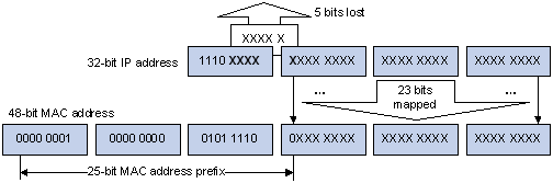
The high-order four bits of the IP multicast address are 1110, representing the multicast ID. Only 23 bits of the remaining 28 bits are mapped to a MAC address. Thus, five bits of the multicast IP address are lost. As a result, 32 IP multicast addresses are mapped to the same MAC address.
Multicast Protocols
![]()
l Generally, we refer to IP multicast working at the network layer as Layer 3 multicast and the corresponding multicast protocols as Layer 3 multicast protocols, which include IGMP, PIM, and MSDP; we refer to IP multicast working at the data link layer as Layer 2 multicast and the corresponding multicast protocols as Layer 2 multicast protocols, which include IGMP Snooping.
l This section provides only general descriptions about applications and functions of the Layer 2 and Layer 3 multicast protocols in a network. For details about these protocols, refer to the related chapters of this configuration guide.
Layer 3 multicast protocols
Layer 3 multicast protocols include multicast group management protocols and multicast routing protocols. Figure 1-5 describes where these multicast protocols are in a network.
Figure 1-5 Positions of Layer 3 multicast protocols
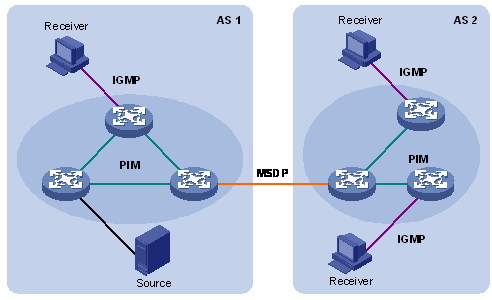
1) Multicast management protocols
Typically, the Internet Group Management Protocol (IGMP) is used between hosts and Layer 3 multicast devices directly connected with the hosts. These protocols define the mechanism of establishing and maintaining group memberships between hosts and Layer 3 multicast devices.
2) Multicast routing protocols
A multicast routing protocol runs on Layer 3 multicast devices to establish and maintain multicast routes and forward multicast packets correctly and efficiently. Multicast routes constitute a loop-free data transmission path from a data source to multiple receivers, namely a multicast distribution tree.
In the ASM model, multicast routes come in intra-domain routes and inter-domain routes.
l An intra-domain multicast routing protocol is used to discover multicast sources and build multicast distribution trees within an autonomous system (AS) so as to deliver multicast data to receivers. Among a variety of mature intra-domain multicast routing protocols, protocol independent multicast (PIM) is a popular one. Based on the forwarding mechanism, PIM comes in two modes – dense mode (often referred to as PIM-DM) and sparse mode (often referred to as PIM-SM).
l An inter-domain multicast routing protocol is used for delivery of multicast information between two ASs. So far, mature solutions include multicast source discovery protocol (MSDP).
For the SSM model, multicast routes are not divided into inter-domain routes and intra-domain routes. Since receivers know the position of the multicast source, channels established through PIM-SM are sufficient for multicast information transport.
Layer 2 multicast protocols
Layer 2 multicast protocols include IGMP Snooping and multicast VLAN. Figure 1-6 shows where these protocols are in the network.
Figure 1-6 Positions of Layer 2 multicast protocols
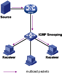
2) IGMP Snooping
Running on Layer 2 devices, Internet Group Management Protocol Snooping (IGMP Snooping) are multicast constraining mechanisms that manage and control multicast groups by listening to and analyzing IGMP messages exchanged between the hosts and Layer 3 multicast devices, thus effectively controlling the flooding of multicast data in a Layer 2 network.
Multicast Packet Forwarding Mechanism
In a multicast model, a multicast source sends information to the host group identified by the multicast group address in the destination address field of the IP packets. Therefore, to deliver multicast packets to receivers located in different parts of the network, multicast routers on the forwarding path usually need to forward multicast packets received on one incoming interface to multiple outgoing interfaces. Compared with a unicast model, a multicast model is more complex in the following aspects.
l In the network, multicast packet transmission is based on the guidance of the multicast forwarding table derived from the unicast routing table or the multicast routing table specially provided for multicast.
l To process the same multicast information from different peers received on different interfaces of the same device, every multicast packet is subject to a reverse path forwarding (RPF) check on the incoming interface. The result of the RPF check determines whether the packet will be forwarded or discarded. The RPF check mechanism is the basis for most multicast routing protocols to implement multicast forwarding.
The RPF mechanism enables multicast devices to forward multicast packets correctly based on the multicast route configuration. In addition, the RPF mechanism also helps avoid data loops caused by various reasons.
Implementation of the RPF Mechanism
Upon receiving a multicast packet that a multicast source S sends to a multicast group G, the multicast device first searches its multicast forwarding table:
1) If the corresponding (S, G) entry exists, and the interface on which the packet actually arrived is the incoming interface in the multicast forwarding table, the router forwards the packet to all the outgoing interfaces.
2) If the corresponding (S, G) entry exists, but the interface on which the packet actually arrived is not the incoming interface in the multicast forwarding table, the multicast packet is subject to an RPF check.
l If the result of the RPF check shows that the RPF interface is the incoming interface of the existing (S, G) entry, this means that the (S, G) entry is correct but the packet arrived from a wrong path and is to be discarded.
l If the result of the RPF check shows that the RPF interface is not the incoming interface of the existing (S, G) entry, this means that the (S, G) entry is no longer valid. The router replaces the incoming interface of the (S, G) entry with the interface on which the packet actually arrived and forwards the packet to all the outgoing interfaces.
3) If no corresponding (S, G) entry exists in the multicast forwarding table, the packet is also subject to an RPF check. The router creates an (S, G) entry based on the relevant routing information and using the RPF interface as the incoming interface, and installs the entry into the multicast forwarding table.
l If the interface on which the packet actually arrived is the RPF interface, the RPF check is successful and the router forwards the packet to all the outgoing interfaces.
l If the interface on which the packet actually arrived is not the RPF interface, the RPF check fails and the router discards the packet.
RPF Check
The basis for an RPF check is a unicast route. A unicast routing table contains the shortest path to each destination subnet. A multicast routing protocol does not independently maintain any type of unicast route; instead, it relies on the existing unicast routing information in creating multicast routing entries.
When performing an RPF check, a router searches its unicast routing table. The specific process is as follows: The router automatically chooses an optimal unicast route by searching its unicast routing table, using the IP address of the “packet source” as the destination address. The outgoing interface in the corresponding routing entry is the RPF interface and the next hop is the RPF neighbor. The router considers the path along which the packet from the RPF neighbor arrived on the RPF interface to be the shortest path that leads back to the source.
Assume that unicast routes exist in the network, as shown in Figure 1-7. Multicast packets travel along the SPT from the multicast source to the receivers.
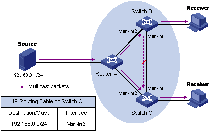
l A multicast packet from Source arrives to VLAN-interface 1 of Switch C, and the corresponding forwarding entry does not exist in the multicast forwarding table of Switch C. Switch C performs an RPF check, and finds in its unicast routing table that the outgoing interface to 192.168.0.0/24 is VLAN-interface 2. This means that the interface on which the packet actually arrived is not the RPF interface. The RPF check fails and the packet is discarded.
l A multicast packet from Source arrives to VLAN-interface 2 of Switch C, and the corresponding forwarding entry does not exist in the multicast forwarding table of Switch C. The router performs an RPF check, and finds in its unicast routing table that the outgoing interface to 192.168.0.0/24 is the interface on which the packet actually arrived. The RPF check succeeds and the packet is forwarded.
IGMP Snooping Overview
Internet Group Management Protocol Snooping (IGMP Snooping) is a multicast constraining mechanism that runs on Layer 2 devices to manage and control multicast groups.
Principle of IGMP Snooping
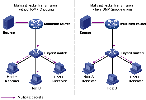
By analyzing received IGMP messages, a Layer 2 device running IGMP Snooping establishes mappings between ports and multicast MAC addresses and forwards multicast data based on these mappings.
As shown in Figure 2-1, when IGMP Snooping is not running on the switch, multicast packets are broadcast to all devices at Layer 2. When IGMP Snooping is running on the switch, multicast packets for known multicast groups are multicast to the receivers, rather than broadcast to all hosts, at Layer 2.
Figure 2-1 Before and after IGMP Snooping is enabled on Layer 2 device
Basic Concepts in IGMP Snooping
IGMP Snooping related ports
As shown in Figure 2-2, Router A connects to the multicast source, IGMP Snooping runs on Switch A and Switch B, Host A and Host C are receiver hosts (namely, multicast group members).
Figure 2-2 IGMP Snooping related ports
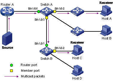
Ports involved in IGMP Snooping, as shown in Figure 2-2, are described as follows:
l Router port: A router port is a port on the Layer 3 multicast device (DR or IGMP querier) side of the device. In the figure, Ethernet 1/0/1 of Switch A and Ethernet 1/0/1 of Switch B are router ports. A device registers all its local router ports in its router port list.
l Member port: A member port is a port on the multicast group member side of the device. In the figure, Ethernet 1/0/2 and Ethernet 1/0/3 of Switch A and Ethernet 1/0/2 of Switch B are member ports. A device records all member ports on the local device in the IGMP Snooping forwarding table.
Port aging timers in IGMP Snooping and related messages and actions
Table 2-1 Port aging timers in IGMP Snooping and related messages and actions
|
Timer |
Description |
Message before expiry |
Action after expiry |
|
Router port aging timer |
For each router port, the device sets a timer initialized to the aging time of the route port |
IGMP general query or PIM hello |
The device removes this port from its router port list |
|
Member port aging timer |
When a port joins a multicast group, the device sets a timer for the port, which is initialized to the member port aging time |
IGMP membership report |
The device removes this port from the multicast group forwarding table |
Work Mechanism of IGMP Snooping
A device running IGMP Snooping performs different actions when it receives different IGMP messages, as follows:
When receiving a general query
The IGMP querier periodically sends IGMP general queries to all hosts and routers on the local subnet to find out whether active multicast group members exist on the subnet.
Upon receiving an IGMP general query, the device forwards it through all ports in the VLAN except the receiving port and performs the following to the receiving port:
l If the receiving port is a router port existing in its router port list, the device resets the aging timer of this router port.
l If the receiving port is not a router port existing in its router port list, the device adds it into its router port list and sets an aging timer for this router port.
When receiving a membership report
A host sends an IGMP report to the multicast router in the following circumstances:
l Upon receiving an IGMP query, a multicast group member host responds with an IGMP report.
l When intended to join a multicast group, a host sends an IGMP report to the multicast router to announce that it is interested in the multicast information addressed to that group.
Upon receiving an IGMP report, the device forwards it through all the router ports in the VLAN, resolves the address of the multicast group the host is interested in, and performs the following to the receiving port:
l If the port is already in the forwarding table, the device resets the member port aging timer of the port.
l If the port is not in the forwarding table, the device installs an entry for this port in the forwarding table and starts the member port aging timer of this port.
![]()
A device will not forward an IGMP report through a non-router port for the following reason: Due to the IGMP report suppression mechanism, if member hosts of that multicast group still exist under non-router ports, the hosts will stop sending reports when they receive the message, and this prevents the device from knowing if members of that multicast group are still attached to these ports.
When receiving a leave message
When an IGMPv1 host leaves a multicast group, the host does not send an IGMP leave message, so the device cannot know immediately that the host has left the multicast group. However, as the host stops sending IGMP reports as soon as it leaves a multicast group, the device deletes the forwarding entry for the member port corresponding to the host from the forwarding table when its aging timer expires.
When an IGMPv2 or IGMPv3 host leaves a multicast group, the host sends an IGMP leave message to the multicast router to announce that it has leaf the multicast group.
Upon receiving an IGMP leave message on the last member port, a device forwards it out all router ports in the VLAN. Because the device does not know whether any other member hosts of that multicast group still exists under the port to which the IGMP leave message arrived, the device does not immediately delete the forwarding entry corresponding to that port from the forwarding table; instead, it resets the aging timer of the member port.
Upon receiving the IGMP leave message from a host, the IGMP querier resolves from the message the address of the multicast group that the host just left and sends an IGMP group-specific query to that multicast group through the port that received the leave message. Upon receiving the IGMP group-specific query, a device forwards it through all the router ports in the VLAN and all member ports of that multicast group, and performs the following to the receiving port:
l If any IGMP report in response to the group-specific query arrives to the member port before its aging timer expires, this means that some other members of that multicast group still exist under that port: the device resets the aging timer of the member port.
l If no IGMP report in response to the group-specific query arrives to the member port before its aging timer expires as a response to the IGMP group-specific query, this means that no members of that multicast group still exist under the port: the device deletes the forwarding entry corresponding to the port from the forwarding table when the aging timer expires.
![]()
After a device enables IGMP Snooping, when it receives the IGMP leave message sent by a host in a multicast group, it judges whether the multicast group exists automatically. If the multicast group does not exist, the device drops this IGMP leave message.
IGMP Snooping Configuration
IGMP Snooping Configuration Task List
Complete the following tasks to configure IGMP Snooping:
|
Operation |
Remarks |
|
Required |
|
|
Optional |
|
|
Optional |
|
|
Optional |
|
|
Optional |
|
|
Configuring the Maximum Number of Multicast Groups on a Port |
Optional |
|
Optional |
|
| Suppressing Flooding of Unknown Multicast Traffic in a VLAN |
Optional |
|
Optional |
|
|
Optional |
|
|
Optional |
|
|
Optional |
|
|
Optional |
Enabling IGMP Snooping
Follow these steps to enable IGMP Snooping:
|
To do… |
Use the command… |
Remarks |
|
Enter system view |
system-view |
— |
|
Enable IGMP Snooping globally |
igmp-snooping enable |
Required By default, IGMP Snooping is disabled globally. |
|
Enter VLAN view |
vlan vlan-id |
— |
|
Enable IGMP Snooping on the VLAN |
igmp-snooping enable |
Required By default, IGMP Snooping is disabled on all the VLANs. |
![]()
l Before enabling IGMP Snooping in a VLAN, be sure to enable IGMP Snooping globally in system view; otherwise the IGMP Snooping settings will not take effect.
l If IGMP Snooping and VLAN VPN are enabled on a VLAN at the same time, IGMP queries are likely to fail to pass the VLAN. You can solve this problem by configuring VLAN tags for queries. For details, see Configuring a VLAN Tag for Query Messages.
Configuring the Version of IGMP Snooping
With the development of multicast technologies, IGMPv3 has found increasingly wide application. In IGMPv3, a host can not only join a specific multicast group but also explicitly specify to receive or reject the information from a specific multicast source. Working with PIM-SSM, IGMPv3 enables hosts to join specific multicast sources and groups directly, greatly simplifying multicast routing protocols and optimizing the network topology.
Follow these steps to configure the version of IGMP Snooping:
|
To do… |
Use the command… |
Remarks |
|
Enter system view |
system-view |
— |
|
Enter VLAN view |
vlan vlan-id |
— |
|
Configure the version of IGMP Snooping |
igmp-snooping version version-number |
Optional The default IGMP Snooping version is version 2. |
![]()
l Before configuring related IGMP Snooping functions, you must enable IGMP Snooping in the specified VLAN.
l Different multicast group addresses should be configured for different multicast sources because IGMPv3 Snooping cannot distinguish multicast data from different sources to the same multicast group.
Configuring Timers
This section describes how to configure the aging timer of the router port, the aging timer of the multicast member ports, and the query response timer.
Follow these steps to configure timers:
|
To do… |
Use the command… |
Remarks |
|
Enter system view |
system-view |
— |
|
Configure the aging timer of the router port |
igmp-snooping router-aging-time seconds |
Optional By default, the aging time of the router port is 105 seconds. |
|
Configure the query response timer |
igmp-snooping max-response-time seconds |
Optional By default, the query response timeout time is 10 seconds. |
|
Configure the aging timer of the multicast member port |
igmp-snooping host-aging-time seconds |
Optional By default, the aging time of multicast member ports is 260 seconds |
Configuring Fast Leave Processing
With fast leave processing enabled, when the device receives an IGMP leave message on a port, the device directly removes that port from the forwarding table entry for the specific group. If only one host is attached to the port, enable fast leave processing to improve bandwidth management.
Enabling fast leave processing in system view
Follow these steps to enable fast leave processing in system view:
|
To do… |
Use the command… |
Remarks |
|
Enter system view |
system-view |
— |
|
Enable fast leave processing |
igmp-snooping fast-leave [ vlan vlan-list ] |
Required By default, the fast leave processing feature is disabled. |
Enabling fast leave processing in Ethernet port view
Follow these steps to enable fast leave processing in Ethernet view:
|
To do… |
Use the command… |
Remarks |
|
Enter system view |
system-view |
— |
|
Enter Ethernet port view |
interface interface-type interface-number |
— |
|
Enable fast leave processing for specific VLANs |
igmp-snooping fast-leave [ vlan vlan-list ] |
Required By default, the fast leave processing feature is disabled. |
![]()
l The fast leave processing function works for a port only if the host attached to the port runs IGMPv2 or IGMPv3.
l The configuration performed in system view takes effect on all ports of the device if no VLAN is specified; if one or more VLANs are specified, the configuration takes effect on all ports in the specified VLAN(s).
l The configuration performed in Ethernet port view takes effect on the port no matter which VLAN it belongs to if no VLAN is specified; if one or more VLANs are specified, the configuration takes effect on the port only if the port belongs to the specified VLAN(s).
l If fast leave processing and unknown multicast packet dropping are enabled on a port to which more than one host is connected, when one host leaves a multicast group, the other hosts connected to port and interested in the same multicast group will fail to receive multicast data for that group.
Configuring a Multicast Group Filter
On an IGMP Snooping-enabled device, the configuration of a multicast group allows the service provider to define restrictions on multicast programs available to different users.
In an actual application, when a user requests a multicast program, the user’s host initiates an IGMP report. Upon receiving this report message, the device checks the report against the ACL rule configured on the receiving port. If the receiving port can join this multicast group, the device adds this port to the IGMP Snooping multicast group list; otherwise the device drops this report message. Any multicast data that has failed the ACL check will not be sent to this port. In this way, the service provider can control the VOD programs provided for multicast users.
Make sure that an ACL rule has been configured before configuring this feature.
Configuring a multicast group filter in system view
Follow these steps to configure a multicast group filter in system view:
|
To do… |
Use the command… |
Remarks |
|
Enter system view |
system-view |
— |
|
Configure a multicast group filter |
igmp-snooping group-policy acl-number [ vlan vlan-list ] |
Required No group filter is configured by default, namely hosts can join any multicast group. |
Configuring a multicast group filter in Ethernet port view
Follow these steps to configure a multicast group filter in Ethernet port view:
|
To do… |
Use the command… |
Remarks |
|
Enter system view |
system-view |
— |
|
Enter Ethernet port view |
interface interface-type interface-number |
— |
|
Configure a multicast group filter |
igmp-snooping group-policy acl-number [ vlan vlan-list ] |
Optional No group filter is configured by default, namely hosts can join any multicast group. |
![]()
l A port can belong to multiple VLANs, you can configure only one ACL rule per VLAN on a port.
l If no ACL rule is configured, all the multicast groups will be filtered.
l Since most devices broadcast unknown multicast packets by default, this function is often used together with the function of dropping unknown multicast packets to prevent multicast streams from being broadcast as unknown multicast packets to a port blocked by this function.
l The configuration performed in system view takes effect on all ports of the device if no VLAN is specified; if one or more VLANs are specified, the configuration takes effect on all ports in the specified VLAN(s).
l The configuration performed in Ethernet port view takes effect on the port no matter which VLAN it belongs to if no VLAN is specified; if one or more VLANs are specified, the configuration takes effect on the port only if the port belongs to the specified VLAN(s).
Configuring the Maximum Number of Multicast Groups on a Port
By configuring the maximum number of multicast groups that can be joined on a port, you can limit the number of multicast programs on-demand available to users, thus to regulate traffic on the port.
Follow these steps to configure the maximum number of multicast groups on a port:
|
To do… |
Use the command… |
Remarks |
|
Enter system view |
system-view |
— |
|
Enter Ethernet port view |
interface interface-type interface-number |
— |
|
Limit the number of multicast groups on a port |
igmp-snooping group-limit limit [ vlan vlan-list [ overflow-replace ] ] |
Required The system default for the device is 256. |
![]()
l To prevent bursting traffic in the network or performance deterioration of the device caused by excessive multicast groups, you can set the maximum number of multicast groups that the device should process.
l When the number of multicast groups exceeds the configured limit, the device removes its multicast forwarding entries starting from the oldest one. In this case, the multicast packets for the removed multicast group(s) will be flooded in the VLAN as unknown multicast packets. As a result, non-member ports can receive multicast packets within a period of time. To avoid this from happening, enable the function of dropping unknown multicast packets.
Configuring IGMP Querier
In an IP multicast network running IGMP, a multicast router or Layer 3 multicast device is responsible for sending IGMP general queries, so that all Layer 3 multicast devices can establish and maintain multicast forwarding entries, thus to forward multicast traffic correctly at the network layer. This router or Layer 3 device is called IGMP querier.
However, a Layer 2 multicast device does not support IGMP, and therefore cannot send general queries by default. By enabling IGMP Snooping on a Layer 2 device in a VLAN where multicast traffic needs to be Layer-2 switched only and no multicast routers are present, the Layer 2 device will act as the IGMP Snooping querier to send IGMP general queries, thus allowing multicast forwarding entries to be established and maintained at the data link layer.
You can also configure the source address, maximum response time and interval of general queries to be sent from the IGMP Snooping querier.
Follow these steps to configure IGMP Snooping querier:
|
To do… |
Use the command… |
Remarks |
|
Enter system view |
system-view |
— |
|
Enable IGMP Snooping |
igmp-snooping enable |
Required By default, IGMP Snooping is disabled. |
|
Enter VLAN view |
vlan vlan-id |
— |
|
Enable IGMP Snooping |
igmp-snooping enable |
Required. |
|
Enable IGMP Snooping querier |
igmp-snooping querier |
Required By default, IGMP Snooping querier is disabled. |
|
Configure the interval of sending general queries |
igmp-snooping query-interval seconds |
Optional By default, the interval of sending general queries is 60 seconds. |
|
Configure the source IP address of general queries |
igmp-snooping general-query source-ip { current-interface | ip-address } |
Optional By default, the source IP address of general queries is 0.0.0.0. |
Suppressing Flooding of Unknown Multicast Traffic in a VLAN
With IGMP Snooping enabled in a VLAN, multicast traffic for unknown multicast groups is flooded within the VLAN by default. This wastes network bandwidth and affects multicast forwarding efficiency.
With the unknown multicast flooding suppression function enabled, when receiving a multicast packet for an unknown multicast group, an IGMP Snooping device creates a nonflooding entry and relays the packet to router ports only, instead of flooding the packet within the VLAN. If the device has no router ports, it drops the multicast packet.
Follow these steps to suppress flooding of unknown multicast traffic in the VLAN:
|
To do… |
Use the command… |
Remarks |
|
Enter system view |
system-view |
— |
|
Enable unknown multicast flooding suppression |
igmp-snooping nonflooding-enable |
Required By default, unknown multicast flooding suppression |
![]()
If the function of dropping unknown multicast packets is enabled, you cannot enable unknown multicast flooding suppression.
Configuring Static Member Port for a Multicast Group
If the host connected to a port is interested in the multicast data for a specific group, you can configure that port as a static member port for that multicast group.
In Ethernet port view
Follow these steps to configure a static multicast group member port in Ethernet port view:
|
To do… |
Use the command… |
Remarks |
|
Enter system view |
system-view |
— |
|
Enter Ethernet port view |
interface interface-type interface-number |
— |
|
Configure the current port as a static member port for a multicast group in a VLAN |
multicast static-group group-address vlan vlan-id |
Required By default, no port is configured as a static multicast group member port. |
In VLAN interface view
Follow these steps to configure a static multicast group member port in VLAN interface view:
|
To do… |
Use the command… |
Remarks |
|
Enter system view |
system-view |
— |
|
Enter VLAN interface view |
interface vlan-interface interface-number |
— |
|
Configure specified port(s) as static member port(s) of a multicast group in the VLAN |
multicast static-group group-address interface interface-list |
Required By default, no port is configured as a static multicast group member port. |
Configuring a Static Router Port
In a network where the topology is unlikely to change, you can configure a port on the device as a static router port, so that the device has a static connection to a multicast router and receives IGMP messages from that router.
In Ethernet port view
Follow these steps to configure a static router port in Ethernet port view:
|
To do… |
Use the command… |
Remarks |
|
Enter system view |
system-view |
— |
|
Enter Ethernet port view |
interface interface-type interface-number |
— |
|
Configure the current port as a static router port |
multicast static-router-port vlan vlan-id |
Required By default, no static router port is configured. |
In VLAN view
Follow these steps to configure a static router port in VLAN view:
|
To do… |
Use the command… |
Remarks |
|
Enter system view |
system-view |
— |
|
Enter VLAN view |
vlan vlan-id |
— |
|
Configure a specified port as a static router port |
multicast static-router-port interface-type interface-number |
Required By default, no static router port is configured. |
Configuring a Port as a Simulated Group Member
Generally, hosts running IGMP respond to the IGMP query messages of the multicast device. If hosts fail to respond for some reason, the multicast device may consider that there is no member of the multicast group on the local subnet and remove the corresponding path.
To avoid this from happening, you can configure a port of the VLAN of the device as a multicast group member. When the port receives IGMP query messages, the multicast device will respond. As a result, the port of the VLAN can continue to receive multicast traffic.
Through this configuration, the following functions can be implemented:
l When an Ethernet port is configured as a simulated member host, the device sends an IGMP report through this port. Meanwhile, the device sends the same IGMP report to itself and establishes a corresponding IGMP entry based on this report.
l When receiving an IGMP general query, the simulated host responds with an IGMP report. Meanwhile, the device sends the same IGMP report to itself to ensure that the IGMP entry does not age out.
l When the simulated joining function is disabled on an Ethernet port, the simulated host sends an IGMP leave message.
Therefore, to ensure that IGMP entries will not age out, the port must receive IGMP general queries periodically.
Follow these steps to configure a port as a simulated group member:
|
To do… |
Use the command… |
Remarks |
|
Enter system view |
system-view |
— |
|
Enter Ethernet port view |
interface interface-type interface-number |
— |
|
Configure the current port as a simulated multicast group member |
igmp host-join group-address [source-ip source-address ] vlan vlan-id |
Optional Simulated joining is disabled by default. |
![]()
l Before configuring a simulated host, enable IGMP Snooping in VLAN view first.
l The port to be configured must belong to the specified VLAN; otherwise the configuration does not take effect.
l You can use the source-ip source-address command to specify a multicast source address that the port will join as a simulated host. This configuration takes effect when IMGPv3 Snooping is enabled in the VLAN.
Configuring a VLAN Tag for Query Messages
By configuring the VLAN tag carried in IGMP general and group-specific queries forwarded and sent by IGMP Snooping devices and by configuring the VLAN mapping function, you can enable multicast packet forwarding between different VLANs In a Layer-2 multicast network environment.
For description about VLAN mapping, see QoS-QoS Profile in H3C WX3000 Series Unified Switches Switching Engine Configuration Guide.
Follow these steps to configure VLAN Tag for query message:
|
To do… |
Use the command… |
Remarks |
|
|
Enter system view |
system-view |
— |
|
|
Enable IGMP Snooping |
igmp-snooping enable |
Required By default, IGMP Snooping is disabled. |
|
|
Configure a VLAN tag for query messages |
igmp-snooping vlan-mapping vlan vlan-id |
Required By default, no VLAN tag is configured for general and group-specific query messages sent or forwarded by IGMP Snooping. |
|
Configuring Multicast VLAN
In traditional multicast implementations, when users in different VLANs listen to the same multicast group, the multicast data is copied on the multicast router for each VLAN that contains receivers. This is a big waste of network bandwidth.
In an IGMP Snooping environment, by configuring a multicast VLAN and adding ports to the multicast VLAN, you can allow users in different VLANs to share the same multicast VLAN. This saves bandwidth because multicast streams are transmitted only within the multicast VLAN. In addition, because the multicast VLAN is isolated from user VLANs, this method also enhances the information security.
Multicast VLAN is mainly used in Layer 2 switching, but you must make the corresponding configurations on the Layer 3 device.
Follow these steps to configure multicast VLAN on the Layer 3 device:
|
To do… |
Use the command… |
Remarks |
|
Enter system view |
system-view |
— |
|
Create a multicast VLAN and enter VLAN view |
vlan vlan-id |
— |
|
Return to system view |
quit |
— |
|
Enter VLAN interface view |
interface Vlan-interface vlan-id |
— |
|
Enable IGMP |
igmp enable |
Required By default, the IGMP feature is disabled. |
|
Return to system view |
quit |
— |
|
Enter Ethernet port view for the Layer 2 device to be configured |
interface interface-type interface-number |
— |
|
Define the port as a trunk or hybrid port |
port link-type { trunk | hybrid } |
Required |
|
Specify the VLANs to be allowed to pass the Ethernet port |
port hybrid vlan vlan-id-list { tagged | untagged } |
Required The multicast VLAN defined on the Layer 2 device must be included, and the port must be configured to forward tagged packets for the multicast VLAN if the port type is hybrid. |
|
port trunk permit vlan vlan-list |
Follow these steps to configure multicast VLAN on the Layer 2 device:
|
To do… |
Use the command… |
Remarks |
|
Enter system view |
system-view |
— |
|
Enable IGMP Snooping |
igmp-snooping enable |
— |
|
Enter VLAN view |
vlan vlan-id |
— |
|
Enable IGMP Snooping |
igmp-snooping enable |
Required |
|
Enable multicast VLAN |
service-type multicast |
Required |
|
Return to system view |
quit |
— |
|
Enter Ethernet port view for the Layer 3 device |
interface interface-type interface-number |
— |
|
Define the port as a trunk or hybrid port |
port link-type { trunk | hybrid } |
Required |
|
Specify the VLANs to be allowed to pass the Ethernet port |
port hybrid vlan vlan-list { tagged | untagged } |
Required The multicast VLAN must be included, and the port must be configured to forward tagged packets for the multicast VLAN if the port type is hybrid. |
|
port trunk permit vlan vlan-list |
||
|
Enter Ethernet port view for a user device |
interface interface-type interface-number |
— |
|
Define the port as a hybrid port |
port link-type hybrid |
Required |
|
Specify the VLANs to be allowed to pass the port |
port hybrid vlan vlan-id-list { tagged | untagged } |
Required The multicast VLAN must be included, and the port must be configured to forward tagged packets for the multicast VLAN. |
![]()
l One port can belong to only one multicast VLAN.
l The port connected to a user terminal must be a hybrid port.
l The multicast member ports must be in the same VLAN with the router port. Otherwise, the multicast member port cannot receive multicast packets.
l If a router port is in a multicast VLAN, the router port must be configured as a trunk port or a hybrid port that allows tagged packets to pass for the multicast VLAN. Otherwise, all the multicast member ports in this multicast VLAN cannot receive multicast packets.
l When the multicast VLAN is set up, all IGMP report messages are forwarded to the router ports in the multicast VLAN. If no router ports exist in the multicast VLAN, all IGMP report messages are flooded within the multicast VLAN.
Displaying and Maintaining IGMP Snooping
|
To do… |
Use the command… |
Remarks |
|
Display the current IGMP Snooping configuration |
display igmp-snooping configuration |
Available in any view |
|
Display IGMP Snooping message statistics |
display igmp-snooping statistics |
|
|
Display the information about IP and MAC multicast groups in one or all VLANs |
display igmp-snooping group [ vlan vlanid ] |
|
|
Clear IGMP Snooping statistics |
reset igmp-snooping statistics |
Available in user view |
IGMP Snooping Configuration Examples
Configuring IGMP Snooping
Network requirements
To prevent multicast traffic from being flooded at Layer 2, enable IGMP Snooping on Layer 2 devices.
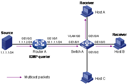
l As shown in Figure 2-3, Router A connects to a multicast source (Source) through GigabitEthernet1/0/2, and to Switch A through GigabitEthernet1/0/1.
l Run PIM-DM and IGMP on Router A. Run IGMP snooping on Switch A. Router A acts as the IGMP querier.
l The multicast source sends multicast data to the multicast group 224.1.1.1. Host A and Host B are receivers of the multicast group 224.1.1.1.
Figure 2-3 Network diagram for IGMP Snooping configuration
Configuration procedure
1) Configure the IP address of each interface
Configure an IP address and subnet mask for each interface as per Figure 2-3. The detailed configuration steps are omitted.
2) Configure Router A
# Enable IP multicast routing, enable PIM-DM on each interface, and enable IGMP on GigabitEthernet1/0/1.
<RouterA> system-view
[RouterA] multicast routing-enable
[RouterA] interface GigabitEthernet 1/0/1
[RouterA-GigabitEthernet1/0/1] igmp enable
[RouterA-GigabitEthernet1/0/1] quit
[RouterA] interface GigabitEthernet 1/0/2
[RouterA-GigabitEthernet1/0/2] pim dm
[RouterA-GigabitEthernet1/0/2] quit
3) Configure Switch A
# Enable IGMP Snooping globally.
<SwitchA> system-view
[SwitchA] igmp-snooping enable
Enable IGMP-Snooping ok.
# Create VLAN 100, assign GigabitEthernet1/0/1 through GigabitEthernet1/0/4 to this VLAN, and enable IGMP Snooping in the VLAN.
[SwitchA] vlan 100
[SwitchA-vlan100] port GigabitEthernet 1/0/1 to GigabitEthernet 1/0/4
[SwitchA-vlan100] igmp-snooping enable
[SwitchA-vlan100] quit
4) Verify the configuration
# View the detailed information of the multicast group in VLAN 100 on Switch A.
<SwitchA> display igmp-snooping group vlan100
Total 1 IP Group(s).
Total 1 MAC Group(s).
Vlan(id):100.
Total 1 IP Group(s).
Total 1 MAC Group(s).
Static Router port(s):
Dynamic Router port(s):
GigabitEthernet1/0/1
IP group(s):the following ip group(s) match to one mac group.
IP group address: 224.1.1.1
Static host port(s):
Dynamic host port(s):
GigabitEthernet1/0/3 GigabitEthernet1/0/4
MAC group(s):
MAC group address: 0100-5e01-0101
Host port(s):GigabitEthernet1/0/3 GigabitEthernet1/0/4
As shown above, the multicast group 224.1.1.1 is established on Switch A, with the dynamic router port GigabitEthernet1/0/1 and dynamic member ports GigabitEthernet1/0/3 and GigabitEthernet1/0/4. This means that Host A and Host B have joined the multicast group 224.1.1.1.
Configuring Multicast VLAN
Network requirements
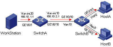
As shown in Figure 2-4, Workstation is a multicast source. Switch A forwards multicast data from the multicast source. A Layer 2 device, Switch B forwards the multicast data to the end users Host A and Host B.
Table 2-2 describes the network devices involved in this example and the configurations you should make on them.
Table 2-2 Network devices and their configurations
|
Device |
Device description |
Networking description |
|
Switch A |
Layer 3 device |
The interface IP address of VLAN 20 is 168.10.1.1. GigabitEthernet 1/0/1 is connected to the workstation and belongs to VLAN 20. The interface IP address of VLAN 10 is 168.10.2.1. GigabitEthernet 1/0/10 belongs to VLAN 10. GigabitEthernet 1/0/10 is connected to Switch B. |
|
Switch B |
Layer 2 device |
VLAN 2 contains GigabitEthernet 1/0/1 and VLAN 3 contains GigabitEthernet 1/0/2. The two ports are connected to Host A and Host B, respectively. VLAN 10 includes GigabitEthernet 1/0/10, GigabitEthernet1/0/1, and GigabitEthernet 1/0/2. GigabitEthernet 1/0/10 is connected to Switch A. VLAN 10 is a multicast VLAN. |
|
Host A |
User 1 |
Host A is connected to GigabitEthernet 1/0/1 on Switch B. |
|
Host B |
User 2 |
Host B is connected to GigabitEthernet 1/0/2 on Switch B. |
Configure a multicast VLAN, so that users in VLAN 2 and VLAN 3 can receive multicast streams through the multicast VLAN.
Figure 2-4 Network diagram for multicast VLAN configuration
Configuration procedure
The following configuration is based on the prerequisite that the devices are properly connected and all the required IP addresses are already configured.
1) Configure Switch A:
# Set the interface IP address of VLAN 20 to 168.10.1.1 and enable PIM DM on the VLAN interface.
<SwitchA> system-view
[SwitchA] multicast routing-enable
[SwitchA] vlan 20
[SwitchA–vlan20]port GigabitEthernet 1/0/1
[SwitchA-vlan20] quit
[SwitchA] interface Vlan-interface 20
[SwitchA-Vlan-interface20] ip address 168.10.1.1 255.255.255.0
[SwitchA-Vlan-interface20] pim dm
[SwitchA-Vlan-interface20] quit
# Configure VLAN 10.
[SwitchA] vlan 10
[SwitchA-vlan10] quit
# Define GigabitEthernet 1/0/10 as a hybrid port, add the port to VLAN 10, and configure the port to forward tagged packets for VLAN 10.
[SwitchA] interface GigabitEthernet 1/0/10
[SwitchA-GigabitEthernet1/0/10] port link-type hybrid
[SwitchA-GigabitEthernet1/0/10] port hybrid vlan 10 tagged
[SwitchA-GigabitEthernet1/0/10] quit
# Configure the interface IP address of VLAN 10 as 168.10.2.1, and enable PIM-DM and IGMP.
[SwitchA] interface Vlan-interface 10
[SwitchA-Vlan-interface10] ip address 168.10.2.1 255.255.255.0
[SwitchA-Vlan-interface10] igmp enable
2) Configure Switch B:
# Enable the IGMP Snooping feature on Switch B.
<SwitchB> system-view
[SwitchB] igmp-snooping enable
# Configure VLAN 10 as the multicast VLAN and enable IGMP Snooping on it.
[SwitchB] vlan 10
[SwitchB-vlan10] service-type multicast
[SwitchB-vlan10] igmp-snooping enable
[SwitchB-vlan10] quit
# Define GigabitEthernet 1/0/10 as a hybrid port, add the port to VLAN 2, VLAN 3, and VLAN 10, and configure the port to forward tagged packets for VLAN 2, VLAN 3, and VLAN 10.
[SwitchB] interface GigabitEthernet 1/0/10
[SwitchB-GigabitEthernet1/0/10] port link-type hybrid
[SwitchB-GigabitEthernet1/0/10] port hybrid vlan 2 3 10 tagged
[SwitchB-GigabitEthernet1/0/10] quit
# Define GigabitEthernet 1/0/1 as a hybrid port, add the port to VLAN 2 and VLAN 10, configure the port to forward untagged packets for VLAN 2 and VLAN 10, and set VLAN 2 as the default VLAN of the port.
[SwitchB] interface GigabitEthernet 1/0/1
[SwitchB-GigabitEthernet1/0/1] port link-type hybrid
[SwitchB-GigabitEthernet1/0/1] port hybrid vlan 2 10 untagged
[SwitchB-GigabitEthernet1/0/1] port hybrid pvid vlan 2
[SwitchB-GigabitEthernet1/0/1] quit
# Define GigabitEthernet 1/0/2 as a hybrid port, add the port to VLAN 3 and VLAN 10, configure the port to forward untagged packets for VLAN 3 and VLAN 10, and set VLAN 3 as the default VLAN of the port.
[SwitchB] interface GigabitEthernet 1/0/2
[SwitchB-GigabitEthernet1/0/2] port link-type hybrid
[SwitchB-GigabitEthernet1/0/2] port hybrid vlan 3 10 untagged
[SwitchB-GigabitEthernet1/0/2] port hybrid pvid vlan 3
[SwitchB-GigabitEthernet1/0/2] quit
Troubleshooting IGMP Snooping
Symptom: Multicast function does not work on the device.
Solution:
Possible reasons are:
1) IGMP Snooping is not enabled.
l Use the display current-configuration command to check the status of IGMP Snooping.
l If IGMP Snooping is disabled, check whether it is disabled globally or in the specific VLAN. If it is disabled globally, use the igmp-snooping enable command in both system view and VLAN view to enable it both globally and on the corresponding VLAN at the same time. If it is only disabled on the corresponding VLAN, use the igmp-snooping enable command in VLAN view only to enable it on the corresponding VLAN.
2) Multicast forwarding table set up by IGMP Snooping is wrong.
l Use the display igmp-snooping group command to check if the multicast groups are expected ones.
l If the multicast group set up by IGMP Snooping is not correct, contact your technical support personnel.
Common Multicast Configuration
Configuring a Multicast MAC Address Entry
In Layer 2 multicast, the system can add multicast forwarding entries dynamically through a Layer 2 multicast protocol. Alternatively, you can statically bind a port to a multicast MAC address entry by configuring a multicast MAC address entry manually.
Generally, when receiving a multicast packet for a multicast group not yet registered on the device, the device will flood the packet within the VLAN to which the port belongs. You can configure a static multicast MAC address entry to avoid this.
Follow these steps to configure a multicast MAC address entry in system view:
|
To do… |
Use the command… |
Remarks |
|
Enter system view |
system-view |
— |
|
Create a multicast MAC address entry |
mac-address multicast mac-address interface interface-list vlan vlan-id |
Required The mac-address argument must be a multicast MAC address. |
Follow these steps to configure a multicast MAC address entry in Ethernet port view:
|
To do… |
Use the command… |
Remarks |
|
Enter system view |
system-view |
— |
|
Enter Ethernet port view |
interface interface-type interface-number |
— |
|
Create a multicast MAC address entry. |
mac-address multicast mac-address vlan vlan-id |
Required The mac-address argument must be a multicast MAC address. |
![]()
l If the multicast MAC address entry to be created already exists, the system gives you a prompt.
l If you want to add a port to a multicast MAC address entry created through the mac-address multicast command, you need to remove the entry first, create this entry again, and then add the specified port to the forwarding ports of this entry.
l You cannot enable link aggregation on a port on which you have configured a multicast MAC address, and you cannot configure a multicast MAC address on an aggregation port.
l You cannot configure a multicast MAC address starting with 01005e in an IGMP-Snooping-enabled VLAN. You can do that if IGMP Snooping is not enabled in the VLAN.
Configuring Dropping Unknown Multicast Packets
Generally, if the multicast address of the multicast packet received on the device is not registered on the local device, the packet will be flooded in the VLAN. When the function of dropping unknown multicast packets is enabled, the device will drop any multicast packets whose multicast address is not registered. Thus, the bandwidth is saved and the processing efficiency of the system is improved.
Follow these steps to configure dropping unknown multicast packet:
|
To do… |
Use the command… |
Remarks |
|
Enter system view |
system-view |
— |
|
Configure dropping unknown multicast packets |
unknown-multicast drop enable |
Required By default, the function of dropping unknown multicast packets is disabled. |
Displaying and Maintaining Common Multicast Configuration
|
To do… |
Use the command… |
Remarks |
|
Display the created multicast MAC table entries |
display mac-address multicast [ static { { { mac-address vlan vlan-id | vlan vlan-id } [ count ] } | count } ] |
You can execute the display commands in any view. |