- Table of Contents
-
- H3C WX3000 Series Unified Switches Switching Engine Configuration Guide-6W103
- 00-Preface
- 01-CLI Configuration
- 02-Login Configuration
- 03-Configuration File Management Configuration
- 04-VLAN Configuration
- 05-Auto Detect Configuration
- 06-Voice VLAN Configuration
- 07-GVRP Configuration
- 08-Basic Port Configuration
- 09-Link Aggregation Configuration
- 10-Port Isolation Configuration
- 11-Port Security-Port Binding Configuration
- 12-DLDP Configuration
- 13-MAC Address Table Management Configuration
- 14-MSTP Configuration
- 15-802.1x and System Guard Configuration
- 16-AAA Configuration
- 17-MAC Address Authentication Configuration
- 18-IP Address and Performance Configuration
- 19-DHCP Configuration
- 20-ACL Configuration
- 21-QoS-QoS Profile Configuration
- 22-Mirroring Configuration
- 23-ARP Configuration
- 24-SNMP-RMON Configuration
- 25-Multicast Configuration
- 26-NTP Configuration
- 27-SSH Configuration
- 28-File System Management Configuration
- 29-FTP-SFTP-TFTP Configuration
- 30-Information Center Configuration
- 31-System Maintenance and Debugging Configuration
- 32-VLAN-VPN Configuration
- 33-HWPing Configuration
- 34-DNS Configuration
- 35-Smart Link-Monitor Link Configuration
- 36-PoE-PoE Profile Configuration
- 37-Routing Protocol Configuration
- 38-UDP Helper Configuration
- 39-Acronyms
- 40-Index
- Related Documents
-
| Title | Size | Download |
|---|---|---|
| 18-IP Address and Performance Configuration | 85.95 KB |
Displaying and Maintaining IP Addressing
IP Address Configuration Examples
IP Address Configuration Example I
IP Address Configuration Example II
2 IP Performance Configuration
Introduction to IP Performance Configuration
Disabling Sending of ICMP Error Packets
Displaying and Maintaining IP Performance Configuration
l The term switch used throughout this document refers to a switching device in a generic sense or the switching engine of the WX3000 series.
l The sample output information in this manual was created on the WX3024. The output information on your device may vary.
IP Addressing Overview
IP Address Classes
IP addressing uses a 32-bit address to identify each host on a network. An example is 01010000100000001000000010000000 in binary. To make IP addresses in 32-bit form easier to read, they are written in dotted decimal notation, each being four octets in length, for example, 10.1.1.1 for the address just mentioned.
Each IP address breaks down into two parts:
l Net ID: The first several bits of the IP address defining a network, also known as class bits.
l Host ID: Identifies a host on a network.
For administration sake, IP addresses are divided into five classes, as shown in the following figure (in which the blue parts represent the address class).

Table 1-1 describes the address ranges of these five classes. Currently, the first three classes of IP addresses are used in quantity.
Table 1-1 IP address classes and ranges
|
Class |
Address range |
Remarks |
|
A |
0.0.0.0 to 127.255.255.255 |
Address 0.0.0.0 means this host no this network. This address is used by a host at bootstrap when it does not know its IP address. This address is never a valid destination address. Addresses starting with 127 are reserved for loopback test. Packets destined to these addresses are processed locally as input packets rather than sent to the link. |
|
B |
128.0.0.0 to 191.255.255.255 |
–– |
|
C |
192.0.0.0 to 223.255.255.255 |
–– |
|
D |
224.0.0.0 to 239.255.255.255 |
Multicast address. |
|
E |
240.0.0.0 to 255.255.255.255 |
Reserved for future use except for the broadcast address 255.255.255.255. |
Special Case IP Addresses
The following IP addresses are for special use, and they cannot be used as host IP addresses:
l IP address with an all-zeros net ID: Identifies a host on the local network. For example, IP address 0.0.0.16 indicates the host with a host ID of 16 on the local network.
l IP address with an all-zeros host ID: Identifies a network.
l IP address with an all-ones host ID: Identifies a directed broadcast address. For example, a packet with the destination address of 192.168.1.255 will be broadcasted to all the hosts on the network 192.168.1.0.
Subnetting and Masking
Subnetting was developed to address the risk of IP address exhaustion resulting from fast expansion of the Internet. The idea is to break a network down into smaller networks called subnets by using some bits of the host ID to create a subnet ID. To identify the boundary between the host ID and the combination of net ID and subnet ID, masking is used.
Each subnet mask comprises 32 bits related to the corresponding bits in an IP address. In a subnet mask, the part containing consecutive ones identifies the combination of net ID and subnet ID whereas the part containing consecutive zeros identifies the host ID.
Figure 1-2 shows how a Class B network is subnetted.
Figure 1-2 Subnet a Class B network

While allowing you to create multiple logical networks within a single Class A, B, or C network, subnetting is transparent to the rest of the Internet. All these networks still appear as one. As subnetting adds an additional level, subnet ID, to the two-level hierarchy with IP addressing, IP routing now involves three steps: delivery to the site, delivery to the subnet, and delivery to the host.
In the absence of subnetting, some special addresses such as the addresses with the net ID of all zeros and the addresses with the host ID of all ones, are not assignable to hosts. The same is true of subnetting. When designing your network, you should note that subnetting is somewhat a tradeoff between subnets and accommodated hosts. For example, a Class B network can accommodate 65,534 (216 – 2. Of the two deducted Class B addresses, one with an all-ones host ID is the broadcast address and the other with an all-zeros host ID is the network address) hosts before being subnetted. After you break it down into 512 (29) subnets by using the first 9 bits of the host ID for the subnet, you have only 7 bits for the host ID and thus have only 126 (27 – 2) hosts in each subnet. The maximum number of hosts is thus 64,512 (512 × 126), 1022 less after the network is subnetted.
Class A, B, and C networks, before being subnetted, use these default masks (also called natural masks): 255.0.0.0, 255.255.0.0, and 255.255.255.0 respectively.
Configuring IP Addresses
The device supports assigning IP addresses to VLAN interfaces and loopback interfaces. Besides directly assigning an IP address to a VLAN interface, you may configure a VLAN interface to obtain an IP address through BOOTP or DHCP as alternatives. If you change the way an interface obtains an IP address, from manual assignment to BOOTP for example, the IP address obtained from BOOTP will overwrite the old one manually assigned.
![]()
This chapter only covers how to assign an IP address manually. For the other two approaches to IP address assignment, refer to the part discussing DHCP in H3C WX3000 Series Unified Switches Switching Engine Configuration Guide.
Follow these steps to assign an IP address to an interface:
|
To do… |
Use the command… |
Remarks |
|
Enter system view |
system-view |
–– |
|
Enter interface view |
interface interface-type interface-number |
–– |
|
Assign an IP address to the interface |
ip address ip-address { mask | mask-length } [ sub ] |
Required No IP address is assigned by default. |
![]()
l You can assign at most two IP address to an interface, among which one is the primary IP address and another is secondary IP addresses. A newly specified primary IP address overwrites the previous one if there is any.
l The primary and secondary IP addresses of an interface cannot reside on the same network segment; the IP address of a VLAN interface must not be on the same network segment as that of a loopback interface on a device.
l A VLAN interface cannot be configured with a secondary IP address if the interface has been configured to obtain an IP address through BOOTP or DHCP.
Displaying and Maintaining IP Addressing
|
To do… |
Use the command… |
Remarks |
|
Display information about a specified or all Layer 3 interfaces |
display ip interface [ interface-type interface-number ] |
Available in any view |
|
Display brief configuration information about a specified or all Layer 3 interfaces |
display ip interface brief [ interface-type [ interface-number ] ] |
IP Address Configuration Examples
IP Address Configuration Example I
Network requirement
As shown in Figure 1-3, assign IP address 129.2.2.1 with mask 255.255.255.0 to VLAN-interface 1 of Switch.
Figure 1-3 Network diagram for IP address configuration

Configuration procedure
# Configure an IP address for VLAN-interface 1.
<device> system-view
[device] interface vlan-interface 1
[device-Vlan-interface1] ip address 129.2.2.1 255.255.255.0
IP Address Configuration Example II
Network requirements
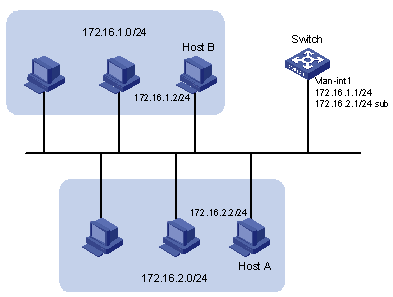
As shown in Figure 1-4, VLAN-interface 1 on Switch is connected to a LAN comprising two segments: 172.16.1.0/24 and 172.16.2.0/24.
To enable the hosts on the two network segments to communicate with the external network through Switch, and the hosts on the LAN can communicate with each other, do the following:
l Assign two IP addresses to VLAN-interface 1 on Switch.
l Set Switch as the gateway on all PCs of the two networks.
Figure 1-4 Network diagram for IP address configuration
Configuration procedure
# Assign a primary IP address and a secondary IP address to VLAN-interface 1.
<Switch> system-view
[Switch] interface vlan-interface 1
[Switch-Vlan-interface1] ip address 172.16.1.1 255.255.255.0
[Switch-Vlan-interface1] ip address 172.16.2.1 255.255.255.0 sub
# Set the gateway address to 172.16.1.1 on the PCs attached to the subnet 172.16.1.0/24, and to 172.16.2.1 on the PCs attached to the subnet 172.16.2.0/24.
# Ping a host on the subnet 172.16.1.0/24 from Switch to check the connectivity.
<Switch> ping 172.16.1.2
PING 172.16.1.2: 56 data bytes, press CTRL_C to break
Reply from 172.16.1.2: bytes=56 Sequence=1 ttl=255 time=25 ms
Reply from 172.16.1.2: bytes=56 Sequence=2 ttl=255 time=27 ms
Reply from 172.16.1.2: bytes=56 Sequence=3 ttl=255 time=26 ms
Reply from 172.16.1.2: bytes=56 Sequence=4 ttl=255 time=26 ms
Reply from 172.16.1.2: bytes=56 Sequence=5 ttl=255 time=26 ms
--- 172.16.1.2 ping statistics ---
5 packet(s) transmitted
5 packet(s) received
0.00% packet loss
round-trip min/avg/max = 25/26/27 ms
The output information shows that Switch can communicate with the hosts on the subnet 172.16.1.0/24.
# Ping a host on the subnet 172.16.2.0/24 from Switch to check the connectivity.
<Switch> ping 172.16.2.2
PING 172.16.2.2: 56 data bytes, press CTRL_C to break
Reply from 172.16.2.2: bytes=56 Sequence=1 ttl=255 time=25 ms
Reply from 172.16.2.2: bytes=56 Sequence=2 ttl=255 time=26 ms
Reply from 172.16.2.2: bytes=56 Sequence=3 ttl=255 time=26 ms
Reply from 172.16.2.2: bytes=56 Sequence=4 ttl=255 time=26 ms
Reply from 172.16.2.2: bytes=56 Sequence=5 ttl=255 time=26 ms
--- 172.16.2.2 ping statistics ---
5 packet(s) transmitted
5 packet(s) received
0.00% packet loss
round-trip min/avg/max = 25/25/26 ms
The output information shows that Switch can communicate with the hosts on the subnet 172.16.2.0/24.
IP Performance Overview
Introduction to IP Performance Configuration
In some network environments, you need to adjust the IP parameters to achieve best network performance. The IP performance configuration supported by the device includes:
l Disabling sending of ICMP error packets
Introduction to FIB
Every device stores a forwarding information base (FIB). FIB is used to store the forwarding information of the device and guide Layer 3 packet forwarding.
You can know the forwarding information of the device through the FIB table. Each FIB entry includes: destination address/mask length, next hop, current flag, timestamp, and outbound interface.
When the device is running normally, the contents of the FIB and the routing table are the same.
Configuring IP Performance
Configuration Task List
Complete the following tasks to configure IP performance:
|
Task |
Remarks |
|
Optional |
|
|
Optional |
Configuring TCP Attributes
TCP optional parameters that can be configured include:
l synwait timer: When sending a SYN packet, TCP starts the synwait timer. If no response packets are received before the synwait timer times out, the TCP connection is not successfully created.
l finwait timer: When the TCP connection is changed into FIN_WAIT_2 state, finwait timer will be started. If no FIN packets are received within the timer timeout, the TCP connection will be terminated. If FIN packets are received, the TCP connection state changes to TIME_WAIT. If non-FIN packets are received, the system restarts the timer from receiving the last non-FIN packet. The connection is broken after the timer expires.
l Size of TCP receive/send buffer
Follow these steps to configure TCP attributes:
|
To do… |
Use the command… |
Remarks |
|
Enter system view |
system-view |
— |
|
Configure TCP synwait timer’s timeout value |
tcp timer syn-timeout time-value |
Optional By default, the timeout value is 75 seconds. |
|
Configure TCP finwait timer’s timeout value |
tcp timer fin-timeout time-value |
Optional By default, the timeout value is 675 seconds. |
|
Configure the size of TCP receive/send buffer |
tcp window window-size |
Optional By default, the buffer is 8 kilobytes. |
Disabling Sending of ICMP Error Packets
Sending error packets is a major function of ICMP protocol. In case of network abnormalities, ICMP packets are usually sent by the network or transport layer protocols to notify corresponding devices so as to facilitate control and management.
By default, the device supports sending ICMP redirect and destination unreachable packets.
Although sending ICMP error packets facilitate control and management, it still has the following disadvantages:
l Sending a lot of ICMP packets will increase network traffic.
l If receiving a lot of malicious packets that cause it to send ICMP error packets, the device’s performance will be reduced.
l As the ICMP redirection function increases the routing table size of a host, the host’s performance will be reduced if its routing table becomes very large.
l If a host sends malicious ICMP destination unreachable packets, end users may be affected.
To prevent the above mentioned problems, you can disable the device from sending such ICMP error packets.
Follow these steps to disable sending of ICMP error packets:
|
To do… |
Use the command… |
Remarks |
|
Enter system view |
system-view |
— |
|
Disable sending of ICMP redirects |
undo icmp redirect send |
Required Enabled by default |
|
Disable sending of ICMP destination unreachable packets |
undo icmp unreach send |
Required Enabled by default |
Displaying and Maintaining IP Performance Configuration
|
To do… |
Use the command… |
Remarks |
|
Display TCP connection status |
display tcp status |
Available in any view |
|
Display TCP connection statistics |
display tcp statistics |
|
|
Display UDP traffic statistics |
display udp statistics |
|
|
Display IP traffic statistics |
display ip statistics |
|
|
Display ICMP traffic statistics |
display icmp statistics |
|
|
Display the current socket information of the system |
display ip socket [ socktype sock-type ] [ task-id socket-id ] |
|
|
Display the forwarding information base (FIB) entries |
display fib |
|
|
Display the FIB entries matching the destination IP address |
display fib ip_address1 [ { mask1 | mask-length1 } [ ip_address2 { mask2 | mask-length2 } | longer ] | longer ] |
|
|
Display the FIB entries permitted by a specific ACL |
display fib acl number |
|
|
Display the FIB entries in the buffer which begin with, include or exclude the specified character string. |
display fib | { begin | include | exclude } regular-expression |
|
|
Display the total number of the FIB entries |
display fib statistics |
|
|
Clear IP traffic statistics |
reset ip statistics |
Available in user view |
|
Clear TCP traffic statistics |
reset tcp statistics |
|
|
Clear UDP traffic statistics |
reset udp statistics |