- Table of Contents
-
- H3C WX3000 Series Unified Switches Switching Engine Configuration Guide-6W103
- 00-Preface
- 01-CLI Configuration
- 02-Login Configuration
- 03-Configuration File Management Configuration
- 04-VLAN Configuration
- 05-Auto Detect Configuration
- 06-Voice VLAN Configuration
- 07-GVRP Configuration
- 08-Basic Port Configuration
- 09-Link Aggregation Configuration
- 10-Port Isolation Configuration
- 11-Port Security-Port Binding Configuration
- 12-DLDP Configuration
- 13-MAC Address Table Management Configuration
- 14-MSTP Configuration
- 15-802.1x and System Guard Configuration
- 16-AAA Configuration
- 17-MAC Address Authentication Configuration
- 18-IP Address and Performance Configuration
- 19-DHCP Configuration
- 20-ACL Configuration
- 21-QoS-QoS Profile Configuration
- 22-Mirroring Configuration
- 23-ARP Configuration
- 24-SNMP-RMON Configuration
- 25-Multicast Configuration
- 26-NTP Configuration
- 27-SSH Configuration
- 28-File System Management Configuration
- 29-FTP-SFTP-TFTP Configuration
- 30-Information Center Configuration
- 31-System Maintenance and Debugging Configuration
- 32-VLAN-VPN Configuration
- 33-HWPing Configuration
- 34-DNS Configuration
- 35-Smart Link-Monitor Link Configuration
- 36-PoE-PoE Profile Configuration
- 37-Routing Protocol Configuration
- 38-UDP Helper Configuration
- 39-Acronyms
- 40-Index
- Related Documents
-
| Title | Size | Download |
|---|---|---|
| 32-VLAN-VPN Configuration | 189.44 KB |
Adjusting the TPID Values of VLAN-VPN Packets
Enabling the VLAN-VPN Feature for a Port
Displaying and Maintaining VLAN-VPN·
VLAN-VPN Configuration Example
Transmitting User Packets through a Tunnel in the Public Network by Using VLAN-VPN
2 Selective QinQ Configuration
Inner-to-Outer Tag Priority Mapping
Enabling the Selective QinQ Feature for a Port
Configuring the Inner-to-Outer Tag Priority Mapping Feature
Selective QinQ Configuration Example
Processing Private Network Packets by Their Types
![]()
l The term switch used throughout this chapter refers to a switching device in a generic sense or the switching engine of a unified switch in the WX3000 series.
l The sample output information in this manual was created on the WX3024. The output information on your device may vary.
VLAN-VPN Overview
Introduction to VLAN-VPN
Virtual private network (VPN) is a new technology that emerges with the expansion of the Internet. It can be used for establishing private networks over the public network. With VPN, you can specify to process packets on the client or the access end of the service provider in specific ways, establish dedicated tunnels for user traffic on public network devices, and thus improve data security.
VLAN-VPN feature is a simple yet flexible Layer 2 tunneling technology. It tags private network packets with outer VLAN tags, thus enabling the packets to be transmitted through the service providers’ backbone networks with both inner and outer VLAN tags. In public networks, packets of this type are transmitted by their outer VLAN tags (that is, the VLAN tags of public networks), and the inner VLAN tags are treated as part of the payload.
Figure 1-1 describes the structure of the packets with single-layer VLAN tags.
Figure 1-1 Structure of packets with single-layer VLAN tags
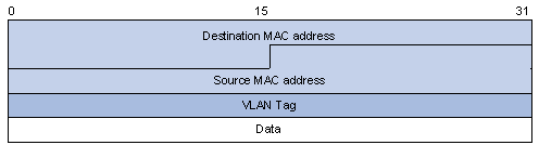
Figure 1-2 describes the structure of the packets with double-layer VLAN tags.
Figure 1-2 Structure of packets with double-layer VLAN tags

Compared with MPLS-based Layer 2 VPN, VLAN-VPN has the following features:
l It provides Layer 2 VPN tunnels that are simpler.
l VLAN-VPN can be implemented through manual configuration. That is, signaling protocol-related configuration is not needed.
The VLAN-VPN feature provides you with the following benefits:
l Saves public network VLAN ID resource.
l You can have VLAN IDs of your own, which is independent of public network VLAN IDs.
l Provides simple Layer 2 VPN solutions for small-sized MANs or intranets.
Implementation of VLAN-VPN
With the VLAN-VPN feature enabled, no matter whether or not a received packet already carries a VLAN tag, the device will tag the received packet with the default VLAN tag of the receiving port and add the source MAC address to the MAC address table of the default VLAN. When a packet reaches a VLAN-VPN-enabled port:
l If the packet already carries a VLAN tag, the packet becomes a dual-tagged packet.
l Otherwise, the packet becomes a packet carrying the default VLAN tag of the port.
Adjusting the TPID Values of VLAN-VPN Packets
Tag protocol identifier (TPID) is a field of the VLAN tag. IEEE 802.1Q specifies the value of TPID to be 0x8100.
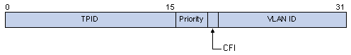
Figure 1-3 illustrates the structure of the Tag packet of an Ethernet frame defined by IEEE 802.1Q.
Figure 1-3 The structure of the Tag packet of an Ethernet frame
By default, the device adopts the TPID value (0x8100) specified in the protocol. Some vendors use other TPID values (such as 0x9100).
To be compatible with devices of other vendors, the device can adjust the TPID values of VLAN-VPN packets globally. You can configure TPID values by yourself. When forwarding packets, the VLAN-VPN uplink port sets the TPID value for outer VLAN tags of these packets to the user-defined value, so that these packets forwarded to the public network can be recognized by devices of other vendors.
As the position of the TPID field in an Ethernet packet is the same as that of the upper-layer protocol type field in a packet without VLAN Tag, to avoid confusion in the process of receiving/forwarding a packet, the TPID value cannot be any of the protocol type value listed in Table 1-1.
Table 1-1 Commonly used protocol type values in Ethernet frames
|
Protocol type |
Value |
|
ARP |
0x0806 |
|
IP |
0x0800 |
|
MPLS |
0x8847/0x8848 |
|
IPX |
0x8137 |
|
IS-IS |
0x8000 |
|
LACP |
0x8809 |
|
802.1x |
0x888E |
VLAN-VPN Configuration
Configuration Task List
Complete the following tasks to configure VLAN-VPN:
|
Task |
Remarks |
|
Required |
|
|
Optional |
Enabling the VLAN-VPN Feature for a Port
Configuration Prerequisites
l The port is not a VLAN-VPN uplink port.
l The port is not a remote mirror reflection port.
Configuration procedure
Follow these steps to enable the VLAN-VPN feature for a port:
|
To do… |
Use the command… |
Remarks |
|
Enter system view |
system-view |
— |
|
Enter Ethernet port view |
interface interface-type interface-number |
— |
|
Enable the VLAN-VPN feature on the port |
vlan-vpn enable |
Required By default, the VLAN-VPN feature is disabled on a port. |
TPID Adjusting Configuration
Configuration Prerequisites
l To change the global TPID value 0x8100, you need to specify a port on the device as a VLAN VPN uplink port. Before the configuration, make sure that VLAN VPN is disabled on the port.
l For proper packet transmission, confirm the TPID value of the peer device in the public network before adjusting the TPID value.
Configuration Procedure
Follow these steps to adjust the TPID value for VLAN-VPN packets on a port:
|
To do… |
Use the command… |
Remarks |
|
Enter system view |
system-view |
— |
|
Set the TPID value globally |
vlan-vpn tpid value |
Required Do not set the TPID value to any of the protocol type values listed in Table 1-1. The default TPID value used on the device is 0x8100. |
|
Enter Ethernet port view |
interface interface-type interface-number |
— |
|
Set the port to be a VLAN-VPN uplink port |
vlan-vpn uplink enable |
Optional By default, the VLAN-VPN uplink function is disabled. |
![]()
l A port cannot be configured as both a VLAN VPN port and a VLAN VPN uplink port at the same time.
l With the TPID being 0x8100, every port can be configured as a VLAN VPN uplink port. However, if the TPID value is not the default value, you need to use the vlan-vpn uplink enable command to specify a VLAN VPN uplink port.
l A VLAN VPN uplink port does not remove the outer VLAN tags of packets to be sent through it, so a VLAN VPN uplink port must be configured as a trunk port or hybrid port and configured to keep the outer VLAN when sending packets of the outer VLAN.
Displaying and Maintaining VLAN-VPN
|
To do… |
Use the command… |
Remarks |
|
Display the VLAN-VPN configurations of all the ports |
display port vlan-vpn |
Available in any view |
VLAN-VPN Configuration Example
Transmitting User Packets through a Tunnel in the Public Network by Using VLAN-VPN
Network requirements
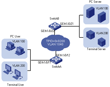
l As shown in Figure 1-4, both Switch A and Switch B are the WX3000 series devices. They connect the users to the servers through the public network.
l PC users and PC servers are in VLAN 100 created in the private network, while terminal users and terminal servers are in VLAN 200, which is also created in the private network. The VLAN VPN connection is established in VLAN 1040 of the public network.
l Switches of other vendors are used in the public network. They use the TPID value 0x9200.
l Employ VLAN-VPN on Switch A and Switch B to enable the PC users and PC servers to communicate with each through a VPN, and employ VLAN-VPN on Switch A and Switch B to enable the Terminal users and Terminal servers to communicate with each other through a VPN.
Figure 1-4 Network diagram for VLAN-VPN configuration
Configuration procedure
l Configure Switch A.
# Enable the VLAN-VPN feature on GigabitEthernet 1/0/11 of Switch A and tag the packets received on this port with the tag of VLAN 1040 as the outer VLAN tag.
<SwitchA> system-view
[SwitchA] vlan 1040
[SwitchA-vlan1040] port GigabitEthernet 1/0/11
[SwitchA-vlan1040] quit
[SwitchA] interface GigabitEthernet 1/0/11
[SwitchA-GigabitEthernet1/0/11] vlan-vpn enable
[SwitchA-GigabitEthernet1/0/11] quit
# Set the global TPID value of Switch A to 0x9200 and configure GigabitEthernet 1/0/12 as a VLAN VPN uplink port, so that Switch A can intercommunicate with devices in the public network.
[SwitchA] vlan-vpn tpid 9200
[SwitchA] interface GigabitEthernet1/0/12
[SwitchA-GigabitEthernet1/0/12] port link-type trunk
[SwitchA-GigabitEthernet1/0/12] port trunk permit vlan 1040
[SwitchA-GigabitEthernet1/0/12] vlan-vpn uplink enable
l Configure Switch B.
# Enable the VLAN-VPN feature on GigabitEthernet 1/0/21 of Switch B and tag the packets received on this port with the tag of VLAN 1040 as the outer VLAN tag.
<SwitchB> system-view
[SwitchB] vlan 1040
[SwitchB-vlan1040] port GigabitEthernet 1/0/21
[SwitchB-vlan1040] quit
[SwitchB] interface GigabitEthernet 1/0/21
[SwitchB-GigabitEthernet1/0/21] vlan-vpn enable
# Set the global TPID value of Switch B to 0x9200 and configure GigabitEthernet 1/0/22 as a VLAN VPN uplink port, so that Switch B can intercommunicate with devices in the public network.
[SwitchB-GigabitEthernet1/0/21] quit
[SwitchB] vlan-vpn tpid 9200
[SwitchB] interface GigabitEthernet1/0/22
[SwitchB-GigabitEthernet1/0/22] port link-type trunk
[SwitchB-GigabitEthernet1/0/22] port trunk permit vlan 1040
[SwitchB-GigabitEthernet1/0/22] vlan-vpn uplink enable
![]()
l Do not configure VLAN 1040 as the default VLAN of GigabitEthernet 1/0/12 of Switch A and GigabitEthernet 1/0/22 of Switch B. Otherwise, the outer VLAN tag of a packet will be removed during transmission.
l In this example, both GigabitEthernet 1/0/11 of Switch A and GigabitEthernet 1/0/21 of Switch B are access ports. In cases where the ports are trunk ports or hybrid ports, you need to configure the two ports to remove the outer VLAN tags before transmitting packets of VLAN 1040. Refer to Port Basic Configuration in H3C WX3000 Series Unified Switches Switching Engine Configuration Guide for detailed configuration.
l Configure the devices in the public network
# As the devices in the public network are from other vendors, only the basic principles are introduced here. That is, you need to configure the devices connecting to GigabitEthernet 1/0/12 of Switch A and GigabitEthernet 1/0/22 of Switch B to permit the corresponding ports to transmit tagged packets of VLAN 1040.
Data transfer process
The following describes how a packet is forwarded from Switch A to Switch B in this example.
1) As GigabitEthernet 1/0/11 of Switch A is a VLAN-VPN port, when a packet from the customer’s network side reaches this port, it is tagged with the default VLAN tag of the port (VLAN 1040).
2) The device sets the TPID value for the outer VLAN tags of packets to user-defined value 0x9200 and then forwards these packets to the public network through the VLAN-VPN uplink port GigabitEthernet 1/0/12.
3) The outer VLAN tag of the packet remains unchanged while the packet travels in the public network, till it reaches GigabitEthernet 1/0/22 of Switch B.
4) After the packet reaches Switch B, it is forwarded to GigabitEthernet 1/0/21 of Switch B. As the port belongs to VLAN 1040 and is an access port, the outer VLAN tag (the tag of VLAN 1040) of the packet is removed before the packet is forwarded, which restores the packet to a packet tagged with only the private VLAN tag and enables it to be forwarded to its destination networks.
5) It is the same case when a packet travels from Switch B to Switch A.
2 Selective QinQ Configuration
Selective QinQ Overview
Selective QinQ Overview
Selective QinQ is an enhanced application of the VLAN-VPN feature. With the selective QinQ feature, you can configure inner-to-outer VLAN tag mapping, according to which you can add different outer VLAN tags to the packets with different inner VLAN tags.
The selective QinQ feature makes the service provider network structure more flexible. You can classify the terminal users on the port connecting to the access layer device according to their VLAN tags, and add different outer VLAN tags to these users. In the public network, you can configure QoS policies based on outer VLAN tags to assign different priorities to different packets, thus providing differentiated services. See Figure 2-1 for details.
Figure 2-1 Diagram for a selective QinQ implementation
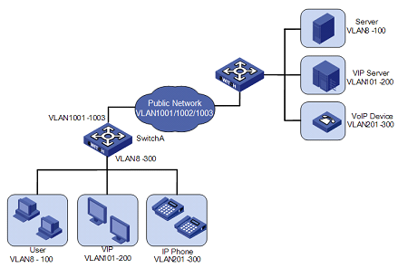
In this implementation, Switch A is an access device of the service provider. The users connecting to it include common customers (in VLAN 8 to VLAN 100), VIPs (in VLAN 101 to VLAN 200), and IP telephone users (in VLAN 201 to VLAN 300). Packets of all these users are forwarded by Switch A to the public network.
After the selective QinQ feature and the inner-to-outer tag mapping feature are enabled on the port connecting Switch A to these users, the port will add different outer VLAN tags to the packets according to their inner VLAN tags. For example, you can configure to add the tag of VLAN 1002 to the packets of IP telephone users in VLAN 201 to VLAN 300 and forward the packets to the VoIP device, which is responsible for processing IP telephone services.
To guarantee the quality of voice packet transmission, you can configure QoS policies in the public network to reserve bandwidth for packets of VLAN 1002 and forward them preferentially.
In this way, you can configure different forwarding policies for data of different type of users, thus improving the flexibility of network management. On the other hand, network resources are well utilized, and users of the same type are also isolated by their inner VLAN tags. This helps to improve network security.
Inner-to-Outer Tag Priority Mapping
As shown in Figure 1-3, the user priority field is the 802.1p priority of the tag. The value of this 3-bit field is in the range 0 to 7. By configuring inner-to-outer tag priority mapping for a VLAN-VPN-enabled port, you can assign outer tags of different priorities to packets according to their inner tag priorities.
Refer to QoS-QoS profile in H3C WX3000 Series Unified Switches Switching Engine Configuration Guide for information about priority.
Selective QinQ Configuration
Configuration Task List
Complete the following tasks to configure selective QinQ:
|
Task |
Remarks |
|
Required |
|
|
Optional |
Enabling the Selective QinQ Feature for a Port
The following configurations are required for the selective QinQ feature:
l Enabling the VLAN-VPN feature on the current port
l Configuring the current port to permit packets of specific VLANs (the VLANs whose tags are to be used as the outer VLAN tags are required)
Follow these steps to enable the selective QinQ feature:
|
To do… |
Use the command… |
|
|
Enter system view |
system-view |
— |
|
Enter Ethernet port view |
interface interface-type interface-number |
— |
|
Configure the outer VLAN tag and enter QinQ view |
vlan-vpn vid vlan-id |
Required |
|
Configure to add outer VLAN tags to the packets with the specific inner VLAN tags |
raw-vlan-id inbound vlan-id-list |
Required By default, the feature of adding an outer VLAN tag to the packets with the specific inner VLAN tags is disabled. |
![]()
You are recommended not to configure both the DHCP snooping and selective Q-in-Q function on the device, which may result in the DHCP snooping to function abnormally.
Configuring the Inner-to-Outer Tag Priority Mapping Feature
Configuration Prerequisites
Enabling the VLAN-VPN feature on the current port
Configuration Procedure
Follow these steps to configure the inner-to-outer tag priority mapping feature:
|
To do… |
Use the command… |
Remarks |
|
Enter system view |
system-view |
— |
|
Enter Ethernet port view |
interface interface-type interface-number |
— |
|
Enable the inner-to-outer tag priority mapping feature and create a priority mapping |
vlan-vpn priority old-priority remark new-priority |
Required By default, the inner-to-outer tag priority mapping feature is not enabled. |
Selective QinQ Configuration Example
Processing Private Network Packets by Their Types
Network requirements
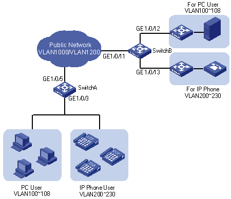
As shown in Figure 2-2:
l GigabitEthernet 1/0/3 of Switch A provides public network access for PC users and IP phone users. PC users belong to VLAN 100 through VLAN 108, and IP phone users belong to VLAN 200 through VLAN 230. GigabitEthernet 1/0/5 of Switch A is connected to the public network. The peer end of Switch A is Switch B.
l GigabitEthernet 1/0/11 of Switch B is connected to the public network. GigabitEthernet 1/0/12 and GigabitEthernet 1/0/13 of Switch B provide network access for PC servers belonging to VLAN 100 through VLAN 108 and voice gateways (for IP phone users) belonging to VLAN 200 through VLAN 230 respectively.
l The public network permits packets of VLAN 1000 and VLAN 1200. Apply QoS policies for these packets to reserve bandwidth for packets of VLAN 1200. That is, packets of VLAN 1200 have higher transmission priority over packets of VLAN 1000.
l Employ the selective QinQ feature on Switch A and Switch B to differentiate traffic of PC users from that of IP phone users, for the purpose of using QoS policies to guarantee higher priority for voice traffic.
l To reduce broadcast packets in the network, enable the inter-VLAN MAC address replicating feature for selective QinQ.
Figure 2-2 Network diagram for selective QinQ configuration
Configuration procedure
l Configure Switch A.
# Create VLAN 1000, VLAN 1200 and VLAN 5 (the default VLAN of GigabitEthernet 1/0/3) on SwitchA.
<SwitchA> system-view
[SwitchA] vlan 1000
[SwitchA-vlan1000] quit
[SwitchA] vlan 1200
[SwitchA-vlan1200] quit
[SwitchA] vlan 5
[SwitchA-vlan5] quit
# Configure GigabitEthernet 1/0/5 as a hybrid port and configure VLAN 5 as its default VLAN. Configure GigabitEthernet 1/0/5 not to remove VLAN tags when forwarding packets of VLAN 5, VLAN 1000, and VLAN 1200.
[SwitchA] interface GigabitEthernet 1/0/5
[SwitchA-GigabitEthernet1/0/5] port link-type hybrid
[SwitchA-GigabitEthernet1/0/5] port hybrid pvid vlan 5
[SwitchA-GigabitEthernet1/0/5] port hybrid vlan 5 1000 1200 tagged
[SwitchA-GigabitEthernet1/0/5] quit
# Configure GigabitEthernet 1/0/3 as a hybrid port and configure GigabitEthernet 1/0/3 to remove VLAN tags when forwarding packets of VLAN 5, VLAN 1000, and VLAN 1200.
[SwitchA] interface GigabitEthernet 1/0/3
[SwitchA-GigabitEthernet1/0/3] port link-type hybrid
[SwitchA-GigabitEthernet1/0/3] port hybrid vlan 5 1000 1200 untagged
# Enable the VLAN-VPN feature on GigabitEthernet 1/0/3.
[SwitchA-GigabitEthernet1/0/3] vlan-vpn enable
# Enable the selective QinQ feature on GigabitEthernet 1/0/3 to tag packets of VLAN 100 through VLAN 108 with the tag of VLAN 1000 as the outer VLAN tag, and tag packets of VLAN 200 through VLAN 230 with the tag of VLAN 1200 as the outer VLAN tag.
[SwitchA-GigabitEthernet1/0/3] vlan-vpn vid 1000
[SwitchA-GigabitEthernet1/0/3-vid-1000] raw-vlan-id inbound 100 to 108
[SwitchA-GigabitEthernet1/0/3-vid-1000] quit
[SwitchA-GigabitEthernet1/0/3] vlan-vpn vid 1200
[SwitchA-GigabitEthernet1/0/3-vid-1200] raw-vlan-id inbound 200 to 230
After the above configuration, packets of VLAN 100 through VLAN 108 (that is, packets of PC users) are tagged with the tag of VLAN 1000 as the outer VLAN tag when they are forwarded to the public network by Switch A; and packets of VLAN 200 through VLAN 230 (that is, packets of IP phone users) are tagged with the tag of VLAN 1200 as the outer VLAN tag when they are forwarded to the public network.
l Configure Switch B.
# Create VLAN 1000, VLAN 1200, VLAN 12 (the default VLAN of GigabitEthernet 1/0/12) and VLAN 13 (the default VLAN of GigabitEthernet 1/0/13) on Switch B.
<SwitchB> system-view
[SwitchB] vlan 1000
[SwitchB-vlan1000] quit
[SwitchB] vlan 1200
[SwitchB-vlan1200] quit
[SwitchB] vlan 12 to 13
# Configure GigabitEthernet 1/0/11 as a hybrid port, and configure GigabitEthernet 1/0/11 not to remove VLAN tags when forwarding packets of VLAN 12, VLAN 13, VLAN 1000, and VLAN 1200.
<SwitchB> system-view
[SwitchB] interface GigabitEthernet 1/0/11
[SwitchB-GigabitEthernet1/0/11] port link-type hybrid
[SwitchB-GigabitEthernet1/0/11] port hybrid vlan 12 13 1000 1200 tagged
# Configure GigabitEthernet 1/0/12 as a hybrid port and configure VLAN 12 as its default VLAN. Configure GigabitEthernet 1/0/12 to remove VLAN tags when forwarding packets of VLAN 12 and VLAN 1000.
[SwitchB] interface GigabitEthernet 1/0/12
[SwitchB-GigabitEthernet1/0/12] port link-type hybrid
[SwitchB-GigabitEthernet1/0/12] port hybrid pvid vlan 12
[SwitchB-GigabitEthernet1/0/12] port hybrid vlan 12 1000 untagged
[SwitchB-GigabitEthernet1/0/12] quit
# Configure GigabitEthernet 1/0/13 as a hybrid port and configure VLAN 13 as its default VLAN . Configure GigabitEthernet 1/0/13 to remove VLAN tags when forwarding packets of VLAN 13 and VLAN 1200.
[SwitchB] interface GigabitEthernet 1/0/13
[SwitchB-GigabitEthernet1/0/13] port link-type hybrid
[SwitchB-GigabitEthernet1/0/13] port hybrid pvid vlan 13
[SwitchB-GigabitEthernet1/0/13] port hybrid vlan 13 1200 untagged
After the above configuration, Switch B can forward packets of VLAN 1000 and VLAN 1200 to the corresponding servers through GigabitEthernet 1/0/12 and GigabitEthernet 1/0/13 respectively.
To make the packets from the servers be transmitted to the clients in the same way, you need to configure the selective QinQ feature on GigabitEthernet 1/0/12 and GigabitEthernet 1/0/13. The configuration on Switch B is similar to that on Switch A and is thus omitted.
![]()
l The port configuration on Switch B is only an example for a specific network requirement. The key to this example is to enable the ports to receive and forward packets of specific VLANs. So you can also configure the ports as access or trunk ports. Refer to Port Basic Configuration in H3C WX3000 Series Unified Switches Switching Engine Configuration Guide for details.
l A selective QinQ-enabled device tags a user packet with an outer VLAN tag regardless of the VLAN tag of the user packet, so there is no need to configure user VLANs on the device.
l Make sure the packets of the default VLAN of a selective QinQ-enabled port are permitted on both the local port and the port connecting to the public network.