- Table of Contents
-
- H3C WX3000 Series Unified Switches Switching Engine Configuration Guide-6W103
- 00-Preface
- 01-CLI Configuration
- 02-Login Configuration
- 03-Configuration File Management Configuration
- 04-VLAN Configuration
- 05-Auto Detect Configuration
- 06-Voice VLAN Configuration
- 07-GVRP Configuration
- 08-Basic Port Configuration
- 09-Link Aggregation Configuration
- 10-Port Isolation Configuration
- 11-Port Security-Port Binding Configuration
- 12-DLDP Configuration
- 13-MAC Address Table Management Configuration
- 14-MSTP Configuration
- 15-802.1x and System Guard Configuration
- 16-AAA Configuration
- 17-MAC Address Authentication Configuration
- 18-IP Address and Performance Configuration
- 19-DHCP Configuration
- 20-ACL Configuration
- 21-QoS-QoS Profile Configuration
- 22-Mirroring Configuration
- 23-ARP Configuration
- 24-SNMP-RMON Configuration
- 25-Multicast Configuration
- 26-NTP Configuration
- 27-SSH Configuration
- 28-File System Management Configuration
- 29-FTP-SFTP-TFTP Configuration
- 30-Information Center Configuration
- 31-System Maintenance and Debugging Configuration
- 32-VLAN-VPN Configuration
- 33-HWPing Configuration
- 34-DNS Configuration
- 35-Smart Link-Monitor Link Configuration
- 36-PoE-PoE Profile Configuration
- 37-Routing Protocol Configuration
- 38-UDP Helper Configuration
- 39-Acronyms
- 40-Index
- Related Documents
-
| Title | Size | Download |
|---|---|---|
| 22-Mirroring Configuration | 129.72 KB |
Table of Contents
Configuring Local Port Mirroring
Configuring Remote Port Mirroring
Configuring MAC-Based Mirroring
Configuring VLAN-Based Mirroring
Displaying and Maintaining Port Mirroring
Mirroring Configuration Example
Local Port Mirroring Configuration Example
Remote Port Mirroring Configuration Example
1 Mirroring Configuration
![]()
l The term switch used throughout this chapter refers to a switching device in a generic sense or the switching engine of a unified switch in the WX3000 series.
l The sample output information in this manual was created on the WX3024. The output information on your device may vary.
Mirroring Overview
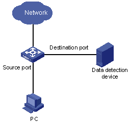
Mirroring refers to the process of copying packets of one or more ports (source ports) to a destination port which is connected to a data detection device. Users can then use the data detection device to analyze the mirrored packets on the destination port for monitoring and troubleshooting the network.
The device supports four kinds of port mirroring:
l Local port mirroring: a device copies packets passing through one or more source ports of the device to the destination port.
l Remote port mirroring implements port mirroring through the remote source mirroring group and remote destination mirroring group. The device copies the packets of the source port to the reflector port, which then broadcasts the packets in the remote-probe VLAN. After the remote device receives the packets, it compares the VLAN ID of the packets with that of the remote-probe VLAN on the remote device. If the VLAN IDs are identical, the remote device forwards the packets to the destination port of the remote destination mirroring group.
l MAC-based mirroring: a device copies packets matching a specified MAC address to the destination port.
l VLAN-based mirroring: a device copies packets of a specified VLAN to the destination port.
Local Port Mirroring
In local port mirroring, packets passing through one or more source ports of a device are copied to the destination port on the same device for packet analysis and monitoring. In this case, the source ports and the destination port must be located on the same device.
Remote Port Mirroring
Remote port mirroring does not require the source and destination ports to be on the same device. The source and destination ports can be located on multiple devices across the network. Therefore, administrators can monitor the traffic on remote devices conveniently.
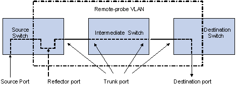
To implement remote port mirroring, a special VLAN, called remote-probe VLAN, is needed. All mirrored packets are sent from the reflector port of the source switch to the monitor port (destination port) of the destination switch through the remote-probe VLAN, so as to implement the monitoring of packets received on and sent from the source switch on the destination switch. Figure 1-2 illustrates the implementation of remote port mirroring.
Figure 1-2 Remote port mirroring application
The switches involved in the remote port mirroring implementation play the following three roles.
l Source switch: The monitored port resident switch. It copies traffic to the reflector port, which then transmits the traffic to an intermediate switch or destination switch through the remote-probe VLAN.
l Intermediate switch: Switches between the source switch and destination switch on the network. An intermediate switch forwards mirrored traffic flows to the next intermediate switch or the destination switch through the remote-probe VLAN. No intermediate switch is present if the source and destination switches directly connect to each other.
l Destination switch: The remote mirroring destination port resident switch. It forwards mirrored traffic flows it received from the remote-probe VLAN to the monitoring device through the destination port.
Table 1-1 describes how the ports on various switches are involved in the mirroring operation.
Table 1-1 Ports involved in the mirroring operation
|
Switch |
Ports involved |
Function |
|
Source switch |
Source port |
Port monitored. It copies packets to the reflector port through local port mirroring. There can be more than one source port. |
|
Reflector port |
Receives packets from the source port and broadcasts the packets in the remote-probe VLAN. |
|
|
Trunk port |
Sends mirrored packets to the intermediate switch or the destination switch. |
|
|
Intermediate switch |
Trunk port |
Sends mirrored packets to the destination switch. Two trunk ports are necessary for the intermediate switch to connect the devices at the source switch side and the destination switch side. |
|
Destination switch |
Trunk port |
Receives remote mirrored packets. |
|
Destination port |
Receives packets forwarded from the trunk port and transmits the packets to the data detection device. |
![]()
l Do not configure a default VLAN, a management VLAN, or a dynamic VLAN as the remote-probe VLAN.
l Configure all ports connecting the devices in the remote-probe VLAN as trunk ports, and ensure the Layer 2 connectivity from the source switch to the destination switch over the remote-probe VLAN.
l Do not configure a Layer 3 interface for the remote-probe VLAN, run other protocol packets, or carry other service packets on the remote-prove VLAN and do not use the remote-prove VLAN as the voice VLAN and protocol VLAN; otherwise, remote port mirroring may be affected.
MAC-Based Mirroring
With MAC-based mirroring configured, a device mirrors packets matching the specified MAC address to the destination port, including:
l Packets with the source MAC address matching the specified MAC address.
l Packets with the destination MAC address matching the specified MAC address.
Compared with port mirroring, MAC-based mirroring is more precise and it can be used to monitor packets of specific device in the network.
VLAN-Based Mirroring
With VLAN-based mirroring configured, a device mirrors packets received on all ports in the specified VLAN to the destination port.
Compared with port mirroring, VLAN-based mirroring is more extensive and it can be used to monitor packets of a specific VLAN or VLANs in the network.
Mirroring Configuration
Complete the following tasks to configure mirroring:
|
Task |
Remarks |
|
Optional |
|
|
Optional |
|
|
Optional |
|
|
Optional |
Configuring Local Port Mirroring
Configuration prerequisites
l The source port is determined and the direction in which the packets are to be mirrored is determined.
l The destination port is determined.
Configuration procedure
Follow these steps to configure local port mirroring:
|
To do… |
Use the command… |
Remarks |
|
|
Enter system view |
system-view |
— |
|
|
Create a port mirroring group |
mirroring-group group-id local |
Required |
|
|
Configure the source port for the port mirroring group |
In system view |
mirroring-group group-id mirroring-port mirroring-port-list { both | inbound | outbound } |
Use either approach You can configure multiple source ports at a time in system view, or you can configure the source port in specific port view. The configurations in the two views have the same effect. |
|
In port view |
interface interface-type interface-number |
||
|
mirroring-group group-id mirroring-port { both | inbound | outbound } |
|||
|
quit |
|||
|
Configure the destination port for the port mirroring group |
In system view |
mirroring-group group-id monitor-port monitor-port-id |
Use either approach The configurations in the two views have the same effect. |
|
In port view |
interface interface-type interface-number |
||
|
mirroring-group group-id monitor-port |
|||
When configuring local port mirroring, note that:
l You need to configure the source and destination ports for the local port mirroring to take effect.
l The source port and the destination port cannot be a member port of an existing mirroring group; besides, the destination port cannot be a member port of an aggregation group or a port enabled with LACP or STP.
Configuring Remote Port Mirroring
![]()
The device can serve as a source switch, an intermediate switch, or a destination switch in a remote port mirroring networking environment.
Configuration on the device acting as a source switch
1) Configuration prerequisites
l The source port, the reflector port, and the remote-probe VLAN are determined.
l Layer 2 connectivity is ensured between the source and destination switches over the remote-probe VLAN.
l The direction of the packets to be monitored is determined.
Follow these steps to configure the source switch:
|
To do… |
Use the command… |
Remarks |
|
Enter system view |
system-view |
— |
|
Create a VLAN and enter the VLAN view |
vlan vlan-id |
vlan-id is the ID of the remote-probe VLAN. |
|
Configure the current VLAN as the remote-probe VLAN |
remote-probe vlan enable |
Required |
|
Return to system view |
quit |
— |
|
Enter the view of the Ethernet port that connects to the intermediate switch or destination switch |
interface interface-type interface-number |
— |
|
Configure the current port as trunk port |
port link-type trunk |
Required By default, the port type is Access. |
|
Configure the trunk port to permit packets from the remote-probe VLAN |
port trunk permit vlan remote-probe-vlan-id |
Required |
|
Return to system view |
quit |
— |
|
Create a remote source mirroring group |
mirroring-group group-id remote-source |
Required |
|
Configure source port(s) for the remote source mirroring group |
mirroring-group group-id mirroring-port mirroring-port-list { both | inbound | outbound } |
Required |
|
Configure the reflector port for the remote source mirroring group |
mirroring-group group-id reflector-port reflector-port |
Required |
|
Configure the remote-probe VLAN for the remote source mirroring group |
mirroring-group group-id remote-probe vlan remote-probe-vlan-id |
Required |
When configuring the source switch, note that:
l All ports of a remote source mirroring group are on the same device. Each remote source mirroring group can be configured with only one reflector port.
l The reflector port cannot be a member port of an existing mirroring group, a member port of an aggregation group, or a port enabled with LACP or STP. It must be an access port and cannot be configured with the functions like VLAN-VPN, port loopback detection, QoS, port security, and so on.
l You cannot modify the duplex mode, port rate, and MDI attribute of a reflector port.
l Only an existing static VLAN can be configured as the remote-probe VLAN. To remove a remote-probe VLAN, you need to restore it to a normal VLAN first. A remote port mirroring group gets invalid if the corresponding remote port mirroring VLAN is removed.
l Do not configure a port connecting the intermediate switch or destination switch as the mirroring source port. Otherwise, traffic disorder may occur in the network.
Configuration on the device acting as an intermediate switch
1) Configuration prerequisites
l The trunk ports and the remote-probe VLAN are determined.
l Layer 2 connectivity is ensured between the source and destination switches over the remote-probe VLAN.
2) Configuration procedure
Follow these steps to configure the intermediate switch:
|
To do… |
Use the command… |
Remarks |
|
Enter system view |
system-view |
— |
|
Create a VLAN and enter VLAN view |
vlan vlan-id |
vlan-id is the ID of the remote-probe VLAN. |
|
Configure the current VLAN as the remote-probe VLAN |
remote-probe vlan enable |
Required |
|
Return to system view |
quit |
— |
|
Enter the view of the Ethernet port connecting to the source switch, destination switch or other intermediate switch |
interface interface-type interface-number |
— |
|
Configure the current port as trunk port |
port link-type trunk |
Required By default, the port type is Access. |
|
Configure the trunk port to permit packets from the remote-probe VLAN |
port trunk permit vlan remote-probe-vlan-id |
Required |
Configuration on the device acting as a destination switch
1) Configuration prerequisites
l The destination port and the remote-probe VLAN are determined.
l Layer 2 connectivity is ensured between the source and destination switches over the remote-probe VLAN.
2) Configuration procedure
Follow these steps to configure remote port mirroring on the destination switch:
|
To do… |
Use the command… |
Remarks |
|
Enter system view |
system-view |
— |
|
Create a VLAN and enter VLAN view |
vlan vlan-id |
vlan-id is the ID of the remote-probe VLAN. |
|
Configure the current VLAN as a remote-probe VLAN |
remote-probe vlan enable |
Required |
|
Return to system view |
quit |
— |
|
Enter the view of the Ethernet port connecting to the source switch or an intermediate switch |
interface interface-type interface-number |
— |
|
Configure the current port as trunk port |
port link-type trunk |
Required By default, the port type is Access. |
|
Configure trunk port to permit packets from the remote-probe VLAN |
port trunk permit vlan remote-probe-vlan-id |
Required |
|
Return to system view |
quit |
— |
|
Create a remote destination mirroring group |
mirroring-group group-id remote-destination |
Required |
|
Configure the destination port for the remote destination mirroring group |
mirroring-group group-id monitor-port monitor-port |
Required |
|
Configure the remote-probe VLAN for the remote destination mirroring group |
mirroring-group group-id remote-probe vlan remote-probe-vlan-id |
Required |
When configuring a destination switch, note that:
l The destination port of remote port mirroring cannot be a member port of an existing mirroring group, a member port of an aggregation group, or a port enabled with LACP or STP.
l Only an existing static VLAN can be configured as the remote-probe VLAN. To remove a remote-probe VLAN, you need to restore it to a normal VLAN first. A remote port mirroring group gets invalid if the corresponding remote port mirroring VLAN is removed.
Configuring MAC-Based Mirroring
![]()
l The MAC address specified for MAC-based mirroring must be a static MAC address existing in the MAC address table.
l You can configure MAC-based mirroring for a remote source mirroring group to implement the MAC-based remote mirroring function.
Configuration prerequisites
l The MAC address to be matched is determined.
l The destination port is determined.
Configuration procedure
Follow these steps to configure MAC-based mirroring:
|
To do… |
Use the command… |
Remarks |
|
Enter system view |
system-view |
— |
|
Create a local or remote source mirroring group |
mirroring-group group-id { local | remote-source } |
Required |
|
Configuring MAC-Based Mirroring |
mirroring-group group-id mirroring-mac mac vlan vlan-id |
Required |
|
Configure the destination port for the mirroring group |
mirroring-group group-id monitor-port monitor-port-id |
Required Note that you need not configure the destination port on the source switch when configuring MAC-based remote mirroring. |
Configuration example
Configure MAC-based mirroring to mirror packets whose source/destination MAC addresses match 000f-e20f-0101 to port GigabitEthernet 1/0/2 on the local device.
Configuration procedure:
<device> system-view
[device] mac-address static 000f-e20f-0101 interface Gigabitethernet 1/0/1 vlan 2
[device] mirroring-group 1 local
[device] mirroring-group 1 mirroring-mac 000f-e20f-0101 vlan 2
[device] mirroring-group 1 monitor-port GigabitEthernet 1/0/2
Configuring VLAN-Based Mirroring
![]()
You can configure VLAN-based mirroring for a remote source mirroring group to implement the VLAN-based remote mirroring function.
Configuration prerequisites
l The VLAN to be monitored is determined.
l The destination port is determined.
Configuration procedure
Follow these steps to configure VLAN-based mirroring:
|
To do… |
Use the command… |
Remarks |
|
Enter system view |
system-view |
— |
|
Create a local or remote source mirroring group |
mirroring-group group-id { local | remote-source } |
Required |
|
Configuring VLAN-Based Mirroring |
mirroring-group group-id mirroring-vlan vlan-id inbound |
Required |
|
Configure the destination port for the mirroring group |
mirroring-group group-id monitor-port monitor-port-id |
Required Note that you need not configure the destination port on the source switch when configuring VLAN-based remote mirroring. |
Configuration example
Configure VLAN-based mirroring to mirror packets received on all ports in VLAN 2 to port GigabitEthernet 1/0/2 on the local device.
Configuration procedure:
<device> system-view
[device] mirroring-group 1 local
[device] mirroring-group 1 mirroring-vlan 2 inbound
[device] mirroring-group 1 monitor-port GigabitEthernet 1/0/2
Displaying and Maintaining Port Mirroring
|
To do… |
Use the command… |
Remarks |
|
Display the information of a mirroring group. |
display mirroring-group { group-id | all | local | remote-destination | remote-source } |
Available in any view |
Mirroring Configuration Example
Local Port Mirroring Configuration Example
Network requirements
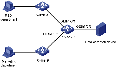
The departments of a company connect to each other through switches, as shown in Figure 1-3:
l Research and Development (R&D) department is connected to Switch C through GigabitEthernet 1/0/1.
l Marketing department is connected to Switch C through GigabitEthernet 1/0/2.
l Data detection device is connected to Switch C through GigabitEthernet 1/0/3
The administrator wants to monitor the packets received on and sent from the R&D department and the marketing department through the data detection device.
Use the local port mirroring function to meet the requirement. Perform the following configurations on Switch C.
l Configure GigabitEthernet 1/0/1 and GigabitEthernet 1/0/2 as mirroring source ports.
l Configure GigabitEthernet 1/0/3 as the mirroring destination port.
Figure 1-3 Network diagram for local port mirroring
Configuration procedure
Configure Switch C:
# Create a local mirroring group.
<device> system-view
[device] mirroring-group 1 local
# Configure the source ports and destination port for the local mirroring group.
[device] mirroring-group 1 mirroring-port GigabitEthernet 1/0/1 GigabitEthernet 1/0/2 both
[device] mirroring-group 1 monitor-port GigabitEthernet 1/0/3
# Display configuration information about local mirroring group 1.
[device] display mirroring-group 1
mirroring-group 1:
type: local
status: active
mirroring port:
GigabitEthernet1/0/1 both
GigabitEthernet1/0/2 both
mirroring mac:
mirroring vlan:
monitor port: GigabitEthernet1/0/3
After the configurations, you can monitor all packets received on and sent from the R&D department and the marketing department on the data detection device.
Remote Port Mirroring Configuration Example
Network requirements
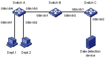
The departments of a company connect to each other through switches, as shown in Figure 1-4:
l Switch A, Switch B, and Switch C are WX3000 series devices.
l Department 1 is connected to GigabitEthernet 1/0/1 of Switch A.
l Department 2 is connected to GigabitEthernet 1/0/2 of Switch A.
l GigabitEthernet 1/0/3 of Switch A connects to GigabitEthernet 1/0/1 of Switch B.
l GigabitEthernet 1/0/2 of Switch B connects to GigabitEthernet 1/0/1 of Switch C.
l The data detection device is connected to GigabitEthernet 1/0/2 of Switch C.
The administrator wants to monitor the packets sent from Department 1 and 2 through the data detection device.
Use the remote port mirroring function to meet the requirement. Perform the following configurations:
l Use Switch A as the source switch, Switch B as the intermediate switch, and Switch C as the destination switch.
l On Switch A, create a remote source mirroring group, configure VLAN 10 as the remote-probe VLAN, ports GigabitEthernet 1/0/1 and GigabitEthernet 1/0/2 as the source ports, and port GigabitEthernet 1/0/4 as the reflector port.
l On Switch B, configure VLAN 10 as the remote-probe VLAN.
l Configure GigabitEthernet 1/0/3 of Switch A, GigabitEthernet 1/0/1 and GigabitEthernet 1/0/2 of Switch B, and GigabitEthernet 1/0/1 of Switch C as trunk ports, allowing packets of VLAN 10 to pass.
l On Switch C, create a remote destination mirroring group, configure VLAN 10 as the remote-probe VLAN, and configure GigabitEthernet 1/0/2 connected with the data detection device as the destination port.
Figure 1-4 Network diagram for remote port mirroring
Configuration procedure
1) Configure the source switch (Switch A)
# Create remote source mirroring group 1.
<device> system-view
[device] mirroring-group 1 remote-source
# Configure VLAN 10 as the remote-probe VLAN.
[device] vlan 10
[device-vlan10] remote-probe vlan enable
[device-vlan10] quit
# Configure the source ports, reflector port, and remote-probe VLAN for the remote source mirroring group.
[device] mirroring-group 1 mirroring-port GigabitEthernet 1/0/1 GigabitEthernet 1/0/2 inbound
[device] mirroring-group 1 reflector-port GigabitEthernet 1/0/4
[device] mirroring-group 1 remote-probe vlan 10
# Configure GigabitEthernet 1/0/3 as trunk port, allowing packets of VLAN 10 to pass.
[device] interface GigabitEthernet 1/0/3
[device-GigabitEthernet1/0/3] port link-type trunk
[device-GigabitEthernet1/0/3] port trunk permit vlan 10
[device-GigabitEthernet1/0/3] quit
# Display configuration information about remote source mirroring group 1.
[device] display mirroring-group 1
mirroring-group 1:
type: remote-source
status: active
mirroring port:
GigabitEthernet1/0/1 inbound
GigabitEthernet1/0/2 inbound
mirroring mac:
mirroring vlan:
reflector port: GigabitEthernet1/0/4
remote-probe vlan: 10
2) Configure the intermediate switch (Switch B)
# Configure VLAN 10 as the remote-probe VLAN.
<device> system-view
[device] vlan 10
[device-vlan10] remote-probe vlan enable
[device-vlan10] quit
# Configure GigabitEthernet 1/0/1 as the trunk port, allowing packets of VLAN 10 to pass.
[device] interface GigabitEthernet 1/0/1
[device-GigabitEthernet1/0/1] port link-type trunk
[device-GigabitEthernet1/0/1] port trunk permit vlan 10
[device-GigabitEthernet1/0/1] quit
# Configure GigabitEthernet 1/0/2 as the trunk port, allowing packets of VLAN 10 to pass.
[device] interface GigabitEthernet 1/0/2
[device-GigabitEthernet1/0/2] port link-type trunk
[device-GigabitEthernet1/0/2] port trunk permit vlan 10
3) Configure the destination switch (Switch C)
# Create remote destination mirroring group 1.
<device> system-view
[device] mirroring-group 1 remote-destination
# Configure VLAN 10 as the remote-probe VLAN.
[device] vlan 10
[device-vlan10] remote-probe vlan enable
[device-vlan10] quit
# Configure the destination port and remote-probe VLAN for the remote destination mirroring group.
[device] mirroring-group 1 monitor-port GigabitEthernet 1/0/2
[device] mirroring-group 1 remote-probe vlan 10
# Configure GigabitEthernet 1/0/1 as the trunk port, allowing packets of VLAN 10 to pass.
[device] interface GigabitEthernet 1/0/1
[device-GigabitEthernet1/0/1] port link-type trunk
[device-GigabitEthernet1/0/1] port trunk permit vlan 10
[device-GigabitEthernet1/0/1] quit
# Display configuration information about remote destination mirroring group 1.
[device] display mirroring-group 1
mirroring-group 1:
type: remote-destination
status: active
monitor port: GigabitEthernet1/0/2
remote-probe vlan: 10
After the configurations, you can monitor all packets sent from Department 1 and 2 on the data detection device.