- Table of Contents
-
- H3C WX3000 Series Unified Switches Switching Engine Configuration Guide-6W103
- 00-Preface
- 01-CLI Configuration
- 02-Login Configuration
- 03-Configuration File Management Configuration
- 04-VLAN Configuration
- 05-Auto Detect Configuration
- 06-Voice VLAN Configuration
- 07-GVRP Configuration
- 08-Basic Port Configuration
- 09-Link Aggregation Configuration
- 10-Port Isolation Configuration
- 11-Port Security-Port Binding Configuration
- 12-DLDP Configuration
- 13-MAC Address Table Management Configuration
- 14-MSTP Configuration
- 15-802.1x and System Guard Configuration
- 16-AAA Configuration
- 17-MAC Address Authentication Configuration
- 18-IP Address and Performance Configuration
- 19-DHCP Configuration
- 20-ACL Configuration
- 21-QoS-QoS Profile Configuration
- 22-Mirroring Configuration
- 23-ARP Configuration
- 24-SNMP-RMON Configuration
- 25-Multicast Configuration
- 26-NTP Configuration
- 27-SSH Configuration
- 28-File System Management Configuration
- 29-FTP-SFTP-TFTP Configuration
- 30-Information Center Configuration
- 31-System Maintenance and Debugging Configuration
- 32-VLAN-VPN Configuration
- 33-HWPing Configuration
- 34-DNS Configuration
- 35-Smart Link-Monitor Link Configuration
- 36-PoE-PoE Profile Configuration
- 37-Routing Protocol Configuration
- 38-UDP Helper Configuration
- 39-Acronyms
- 40-Index
- Related Documents
-
| Title | Size | Download |
|---|---|---|
| 08-Basic Port Configuration | 139.61 KB |
Table of Contents
Types and Numbers of Ethernet Ports
Configuring the Default VLAN ID for an Ethernet Port
Adding an Ethernet Port to Specified VLANs
Making Basic Port Configuration
Configuring Port Auto-Negotiation Speed
Setting the Ethernet Port Broadcast Suppression Ratio
Enabling Flow Control on a Port
Configuring Access Port Attribute
Configuring Hybrid Port Attribute
Configuring Trunk Port Attribute
Disabling Up/Down Log Output on a Port
Copying Port Configuration to Other Ports
Setting Loopback Detection for an Ethernet Port
Configuring the Ethernet Port to Run Loopback Test
Enabling the System to Test Connected Cable
Configuring the Interval to Perform Statistical Analysis on Port Traffic
Displaying and Maintaining Ethernet Ports
Ethernet Port Configuration Example
Troubleshooting Ethernet Port Configuration
![]()
l The term switch used throughout this chapter refers to a switching device in a generic sense or the switching engine of a unified switch in the WX3000 series.
l The sample output information in this manual was created on the WX3024. The output information on your device may vary.
Ethernet Port Overview
Types and Numbers of Ethernet Ports
Table 1-1 lists the types and numbers of the Ethernet ports available on the WX3000 series devices.
Table 1-1 Description of Ethernet port type and port number
|
Series |
10/100/1000Base-T autosensing Ethernet ports |
1000Base-X SFP ports |
Extension slots |
|
WX3024 |
24 |
4 |
2 |
|
WX3010 |
8 |
2 |
None |
|
WX3008 |
8 |
None |
None |
Combo Ports Mapping Relations
An SFP port and its corresponding 10/100/1000Base-T autosensing Ethernet port form a Combo port. That is, only one of the two ports forming the Combo port can be used at a time. Table 1-2 shows the mapping relations between the ports forming the Combo port.
Table 1-2 Mapping relations between the ports forming the Combo port
|
Series |
1000Base-X SFP port |
10/100/1000Base-T autosensing Ethernet port |
|
WX3024 |
GigabitEthernet 1/0/25 |
GigabitEthernet 1/0/22 |
|
GigabitEthernet 1/0/26 |
GigabitEthernet 1/0/24 |
|
|
GigabitEthernet 1/0/27 |
GigabitEthernet 1/0/21 |
|
|
GigabitEthernet 1/0/28 |
GigabitEthernet 1/0/23 |
Link Types of Ethernet Ports
An Ethernet port of the device can operate in one of the following three link types:
l Access: An access port can belong to only one VLAN, and is generally used to connect user PCs.
l Trunk: A trunk port can belong to more than one VLAN. It can receive/send packets from/to multiple VLANs, and is generally used to connect another device.
l Hybrid: A hybrid port can belong to more than one VLAN. It can receive/send packets from/to multiple VLANs, and can be used to connect either a device or user PC.
![]()
A hybrid port allows the packets of multiple VLANs to be sent without tags, but a trunk port only allows the packets of the default VLAN to be sent without tags.
You can configure all the three types of ports on the same Ethernet switch. However, note that you cannot directly switch a port between trunk and hybrid and you must set the port as access before the switching. For example, to change a trunk port to hybrid, you must first set it as access and then hybrid.
Configuring the Default VLAN ID for an Ethernet Port
An access port can belong to only one VLAN. Therefore, the VLAN an access port belongs to is also the default VLAN of the access port. A hybrid/trunk port can belong to several VLANs, and so a default VLAN ID for the port is required.
l After you configure default VLAN IDs for Ethernet ports, the packets passing through the ports are processed in different ways depending on different situations:
Table 1-3 Processing of incoming/outgoing packets
|
Port type |
Processing of an incoming packet |
Processing of an outgoing packet |
|
|
If the packet does not carry a VLAN tag |
If the packet carries a VLAN tag |
||
|
Access |
Receive the packet and add the default tag to the packet. |
l If the VLAN ID is just the default VLAN ID, receive the packet. l If the VLAN ID is not the default VLAN ID, discard the packet. |
Deprive the tag from the packet and send the packet. |
|
Trunk |
l If the VLAN ID is just the default VLAN ID, receive the packet. l If the VLAN ID is not the default VLAN ID but is one of the VLAN IDs allowed to pass through the port, receive the packet. l If the VLAN ID is neither the default VLAN ID, nor one of the VLAN IDs allowed to pass through the port, discard the packet. |
l If the VLAN ID is just the default VLAN ID, deprive the tag and send the packet. l If the VLAN ID is not the default VLAN ID, keep the original tag unchanged and send the packet. |
|
|
Hybrid |
l If the VLAN ID is just the default VLAN ID, deprive the tag and send the packet. l If the VLAN ID is not the default VLAN ID, deprive the tag or keep the tag unchanged (whichever is done is determined by the port hybrid vlan vlan-id-list { tagged | untagged } command) and send the packet. |
||
![]()
To guarantee the proper packet forwarding, the default VLAN ID of the local hybrid port or trunk port should be identical with that of the hybrid port or trunk port on the peer device.
Adding an Ethernet Port to Specified VLANs
You can add the specified Ethernet port to a specified VLAN. After that, the Ethernet port can forward the packets of the specified VLAN, so that the VLAN on this switch can intercommunicate with the same VLAN on the peer device.
An access port can only be added to one VLAN, while hybrid and trunk ports can be added to multiple VLANs.
Note that the port shall be added to an existing VLAN.
Configuring Ethernet Ports
Making Basic Port Configuration
Follow these steps to make basic port configuration:
|
To do… |
Use the command… |
Remarks |
|
Enter system view |
system-view |
— |
|
Enter Ethernet port view |
interface interface-type interface-number |
— |
|
Enable the Ethernet port |
undo shutdown |
By default, the port is enabled. Use the shutdown command to disable the port. |
|
Set the description of the Ethernet port |
description text |
By default, no description is defined for an Ethernet port. |
|
Set the duplex mode of the Ethernet port |
duplex { auto | full | half } |
The port defaults to auto (autonegotiation) mode. |
|
Set the rate of the Ethernet port |
speed { 10 | 100 | 1000 | auto } |
By default, the speed of the port is set to auto mode. |
|
Set the MDI attribute of the Ethernet port |
mdi { across | auto | normal } |
Be default, the MDI attribute of the port is set to auto mode. |
|
Allow jumbo frames that are not larger than 4096 bytes to pass through the Ethernet port |
jumboframe enable |
Optional By default, jumbo frames that are not larger than 4096 bytes are allowed to pass through the port. |
![]()
l For a combo port, only after the optical interface has been configured with the shutdown command can the electrical interface be used, and vice versa.
l The speed and mdi commands are not available on the combo port.
l The mdi command is not available on the Ethernet ports of the expansion interface card.
Configuring Port Auto-Negotiation Speed
You can configure an auto-negotiation speed for a port by using the speed auto command.
Take a 10/100/1000 Mbps port as an example.
l If you expect that 10 Mbps is the only available auto-negotiation speed of the port, you just need to configure speed auto 10.
l If you expect that 10 Mbps and 100 Mbps are the available auto-negotiation speeds of the port, you just need to configure speed auto 10 100.
l If you expect that 10 Mbps and 1000 Mbps are the available auto-negotiation speeds of the port, you just need to configure speed auto 10 1000.
Follow these steps to configure auto-negotiation speeds for a port:
|
To do… |
Use the command… |
Remarks |
|
system-view |
— |
|
|
Enter Ethernet interface view |
interface interface-type interface-number |
— |
|
Configure the available auto-negotiation speed(s) for the port |
speed auto [ 10 | 100 | 1000 ]* |
Optional By default, the port speed is auto-negotiated. |
![]()
l Only ports on the front panel of the device support the auto-negotiation speed configuration feature. And ports on the extended interface card do not support this feature currently.
l After you configure auto-negotiation speed(s) for a port, if you execute the undo speed command or the speed auto command, the auto-negotiation speed setting of the port restores to the default setting.
l The effect of executing speed auto 10 100 1000 equals to that of executing speed auto, that is, the port is configured to support all the auto-negotiation speeds: 10 Mbps, 100 Mbps, and 1000 Mbps.
Setting the Ethernet Port Broadcast Suppression Ratio
You can use the broadcast-suppression commands to restrict the broadcast traffic allowed to pass through a port. After that, if the broadcast traffic on the port exceeds the value you set, the system will maintain an appropriate broadcast traffic ratio by discarding the overflow traffic, so as to suppress broadcast storm, avoid network congestion and ensure normal network services.
You can execute the broadcast-suppression command in system view or Ethernet port view:
l If you execute the command in system view, the command takes effect on all ports.
l If you execute the command in Ethernet port view, the command takes effect only on current port.
Follow these steps to set the Ethernet port broadcast suppression ratio:
|
To do… |
Use the command… |
Remarks |
|
Enter system view |
system-view |
— |
|
Set the global broadcast suppression ratio |
broadcast-suppression { ratio | pps max-pps } |
By default, the ratio is 100%, that is, the system does not suppress broadcast traffic globally. |
|
Enter Ethernet port view |
interface interface-type interface-number |
— |
|
Set the broadcast suppression ratio on current port |
broadcast-suppression { ratio | pps max-pps } |
By default, the ratio is 100%, that is, the system does not suppress broadcast traffic on the port. |
Enabling Flow Control on a Port
After flow control is enabled on both the local and the peer devices, if congestion occurs on the local device, the device will inform its peer to suspend packet sending or lower the packet sending rate. In this way, packet loss is reduced and normal network services are guaranteed.
Follow these steps to enable flow control on a port:
|
To do… |
Use the command… |
Remarks |
|
Enter system view |
system-view |
— |
|
Enter Ethernet port view |
interface interface-type interface-number |
— |
|
Enable flow control on the Ethernet port |
flow-control |
Required By default, flow control is not enabled on a port. |
Configuring Access Port Attribute
Follow these steps to configure access port attribute:
|
To do… |
Use the command… |
Remarks |
|
Enter system view |
system-view |
— |
|
Enter Ethernet port view |
interface interface-type interface-number |
— |
|
Configure the link type for the port as access |
port link-type access |
By default, the link type for the port is access. |
|
Add the current access port into the specified VLAN |
port access vlan vlan-id |
Optional |
Configuring Hybrid Port Attribute
Follow these steps to configure hybrid port attribute:
|
To do… |
Use the command… |
Remarks |
|
Enter system view |
system-view |
— |
|
Enter Ethernet port view |
interface interface-type interface-number |
— |
|
Set the link type for the port as hybrid |
port link-type hybrid |
Required |
|
Set the default VLAN ID for the hybrid port |
port hybrid pvid vlan vlan-id |
Optional By default, the VLAN of a hybrid port is VLAN 1. |
|
Add the current hybrid port into the specified VLAN |
port hybrid vlan vlan-id-list { tagged | untagged } |
Optional For a hybrid port, you can configure to tag the packets of specific VLANs, based on which the packets of those VLANs can be processed in differently ways. |
Configuring Trunk Port Attribute
Follow these steps to configure trunk port attribute:
|
To do… |
Use the command… |
Remarks |
|
Enter system view |
System-view |
— |
|
Enter Ethernet port view |
interface interface-type interface-number |
— |
|
Set the link type for the port as trunk |
port link-type trunk |
Required |
|
Set the default VLAN ID for the trunk port |
port trunk pvid vlan vlan-id |
Optional By default, the VLAN of a trunk port is VLAN 1. |
|
Add the current trunk port into the specified VLAN |
port trunk permit vlan { vlan-id-list | all } |
Optional |
Disabling Up/Down Log Output on a Port
An Ethernet port has two physical link statuses: UP and Down. When the link status of an Ethernet port changes, the device sends log information to the log server, which then acts accordingly. If the status of Ethernet ports changes frequently, the device sends log information to the log server frequently, burdening the log server and consuming plenty of network resources.
To solve this problem, you can disable the Up/Down log output function on some ports, so as to reduce the quantity of log information output to the log server.
![]()
Configuration tasks
Follow these steps to disable a port from outputting UP/Down log information:
|
To do… |
Use the command… |
Remarks |
|
Enter system view |
system-view |
— |
|
Enter Ethernet port view |
interface interface-type interface-number |
— |
|
Disable a port from outputting UP/Down Log Information |
undo enable log updown |
Required By default, a port is allowed to output the UP/Down log information. |
Configuration example
# By default, port GigabitEthernet 1/0/1 is allowed to output the Up/Down log information. Execute the shutdown command or the undo shutdown command on GigabitEthernet 1/0/1, and the system outputs Up/Down log information of GigabitEthernet 1/0/1.
<device> system-view
[device] interface GigabitEthernet 1/0/1
[device-GigabitEthernet1/0/1] shutdown
[device-GigabitEthernet1/0/1]
%Apr 2 08:11:14:220 2000 device L2INF/5/PORT LINK STATUS CHANGE:- 1 -
GigabitEthernet1/0/1 is DOWN
[device-GigabitEthernet1/0/1] undo shutdown
[device-GigabitEthernet1/0/1]
%Apr 2 08:11:32:253 2000 device L2INF/5/PORT LINK STATUS CHANGE:- 1 -
GigabitEthernet1/0/1 is UP
# Disable GigabitEthernet 1/0/1 from outputting Up/Down log information, execute the shutdown command or the undo shutdown command on GigabitEthernet 1/0/1, and no Up/Down log information is output for GigabitEthernet 1/0/1.
[device-GigabitEthernet1/0/1] undo enable log updown
[device-GigabitEthernet1/0/1] shutdown
[device-GigabitEthernet1/0/1] undo shutdown
Copying Port Configuration to Other Ports
To make some other ports have the same configuration as that of a specific port, you can copy the configuration of the specific port to the ports.
Specifically, the following types of port configuration can be copied from one port to other ports: VLAN configuration, protocol-based VLAN configuration, LACP configuration, QoS configuration, GARP configuration, STP configuration and initial port configuration. For the detailed copy content, please refer to the Command Reference.
Follow these steps to copy port configuration to other ports:
|
To do… |
Use the command… |
Remarks |
|
Enter system view |
system-view |
— |
|
Copy port configuration to other ports |
copy configuration source { interface-type interface-number | aggregation-group source-agg-id } destination { interface-list [ aggregation-group destination-agg-id ] | aggregation-group destination-agg-id } |
Required |
![]()
l If you specify the source aggregation group ID, the system uses the port with the smallest port number in the aggregation group as the source.
l If you specify the destination aggregation ID, the configuration of the source port will be copied to all ports in the aggregation group.
Configuring a Port Group
To make the configuration task easier for users, certain devices allow users to configure on a single port as well as on multiple ports in a port group. In port group view, the user only needs to input the configuration command once on one port and that configuration will apply to all ports in the port group. This effectively reduces redundant configurations.
A Port group could be manually created by users. Multiple Ethernet ports can be added to the same port group but one Ethernet port can only be added to one port group.
Follow these steps to configure a port group:
|
To do… |
Use the command… |
Remarks |
|
Enter system view |
system-view |
— |
|
Create a port group or enter the specified port group view |
port-group group-id |
Required |
|
Add an Ethernet port to a specified port group |
port interface-list |
Required |
![]()
A port can not be added to a port group if it has been added to an aggregation group, and vice versa.
Setting Loopback Detection for an Ethernet Port
Loopback detection is used to monitor if loopback occurs on a port.
After you enable loopback detection on Ethernet ports, the device can monitor if external loopback occurs on them. If there is a loopback port found, the device will put it under control.
l If loopback is found on an access port, the system disables the port, sends a Trap message to the client and removes the corresponding MAC forwarding entry.
l If loopback is found on a trunk or hybrid port, the system sends a Trap message to the client. When the loopback port control function is enabled on these ports, the system disables the port, sends a Trap message to the client and removes the corresponding MAC forwarding entry.
Follow these steps to set loopback detection for an Ethernet port:
|
To do… |
Use the command… |
Remarks |
|
Enter system view |
system-view |
— |
|
Enable loopback detection globally |
loopback-detection enable |
Required By default, loopback detection is disabled globally. |
|
Set time interval for port loopback detection |
loopback-detection interval-time time |
Optional The default interval is 30 seconds. |
|
Enter Ethernet port view |
interface interface-type interface-number |
— |
|
Enable loopback detection on a specified port |
loopback-detection enable |
Required By default, port loopback detection is disabled. |
|
Enable loopback port control on the trunk or hybrid port |
loopback-detection control enable |
Optional By default, loopback port control is not enabled. |
|
Configure the system to run loopback detection on all VLANs for the trunk and hybrid ports |
loopback-detection per-vlan enable |
Optional By default, the system runs loopback detection only on the default VLAN for the trunk and hybrid ports. |
![]()
l To enable loopback detection on a specific port, you must use the loopback-detection enable command in both system view and the specific port view.
l After you use the undo loopback-detection enable command in system view, loopback detection will be disabled on all ports.
l The commands of loopback detection feature cannot be configured with the commands of port link aggregation at the same time.
Configuring the Ethernet Port to Run Loopback Test
You can configure the Ethernet port to run loopback test to check if it operates normally. The port running loopback test cannot forward data packets normally. The loopback test terminates automatically after a specific period.
Follow these steps to configure an Ethernet port to run loopback test:
|
To do… |
Use the command… |
Remarks |
|
Enter system view |
system-view |
— |
|
Enter Ethernet port view |
interface interface-type interface-number |
— |
|
Configure the Ethernet port to run loopback test |
loopback { external | internal } |
Required |
![]()
l external: Performs external loop test. In the external loop test, self-loop headers (which are made from four cores of the 8-core cables) must be used on the ports of the device. The external loop test can locate the hardware failures on the port.
l internal: Performs internal loop test. In the internal loop test, self loop is established in the switching chip to locate the chip failure which is related to the port.
After you use the shutdown command on a port, the port cannot run loopback test. You cannot use the speed, duplex, mdi and shutdown commands on the ports running loopback test. Some ports do not support loopback test, and corresponding prompts will be given when you perform loopback test on them.
Enabling the System to Test Connected Cable
You can enable the system to test the cable connected to a specific port. The test result will be returned in five minutes. The system can test these attributes of the cable: Receive and transmit directions (RX and TX), short circuit/open circuit or not, the length of the faulty cable.
Follow these steps to enable the system to test connected cables:
|
To do… |
Use the command… |
Remarks |
|
Enter system view |
system-view |
— |
|
Enter Ethernet port view |
interface interface-type interface-number |
— |
|
Enable the system to test connected cables |
virtual-cable-test |
Required |
![]()
l Optical port (including Combo optical port) does not support VCT (virtual-cable-test) function.
l Combo electrical port supports VCT function only when it is in UP condition (using undo shutdown command), normal Ethernet electrical port always supports this function.
Configuring the Interval to Perform Statistical Analysis on Port Traffic
By performing the following configuration, you can set the interval to perform statistical analysis on the traffic of a port.
When you use the display interface interface-type interface-number command to display the information of a port, the system performs statistical analysis on the traffic flow passing through the port during the specified interval and displays the average rates in the interval. For example, if you set this interval to 100 seconds, the displayed information is as follows:
Last 100 seconds input: 0 packets/sec 0 bytes/sec
Last 100 seconds output: 0 packets/sec 0 bytes/sec
Follow these steps to set the interval to perform statistical analysis on port traffic:
|
To do… |
Use the command… |
Remarks |
|
Enter system view |
system-view |
— |
|
Enter Ethernet port view |
interface interface-type interface-number |
— |
|
Set the interval to perform statistical analysis on port traffic |
flow-interval interval |
Optional By default, this interval is 300 seconds. |
Displaying and Maintaining Ethernet Ports
|
To do… |
Use the command… |
Remarks |
|
Display port configuration information |
display interface [ interface-type | interface-type interface-number ] |
Available in any view |
|
Display information for a specified port group |
display port-group group-id |
|
|
Display port loopback detection state |
||
|
Display brief configuration information about one or all ports |
display brief interface [ interface-type [ interface-number ] ] [ | { begin | include | exclude } regular-expression ] |
|
|
Display current type-specific ports |
display port { hybrid | trunk | combo } |
|
|
Display port information about a specified unit |
display unit unit-id interface |
|
|
Clear the statistics of the port |
reset counters interface [ interface-type | interface-type interface-number ] |
After 802.1X is enabled, the port information cannot be reset. |
Ethernet Port Configuration Example
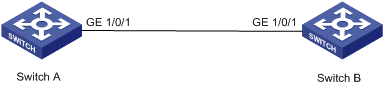
Network requirements
As shown in Figure 1-1:
l Switch A is connected to Switch B through trunk port GigabitEthernet 1/0/1.
l Configure the default VLAN ID for the trunk port as 100.
l Allow the packets of VLAN 2, VLAN 6 through VLAN 50 and VLAN 100 to pass the port.
Figure 1-1 Network diagram for default VLAN ID configuration
Configuration procedure
The following configuration is used for Switch A. Configure Switch B in a similar way.
# Enter port view of GigabitEthernet 1/0/1.
[device] interface GigabitEthernet1/0/1
# Set GigabitEthernet 1/0/1 as a trunk port and allow the packets of VLAN 2, VLAN 6 through VLAN 50 and VLAN 100 to pass the port.
[device-GigabitEthernet1/0/1] port link-type trunk
[device-GigabitEthernet1/0/1] port trunk permit vlan 2 6 to 50 100
# Create VLAN 100.
[device] vlan 100
# Configure the default VLAN ID of GigabitEthernet 1/0/1 as 100.
[device-GigabitEthernet1/0/1] port trunk pvid vlan 100
Troubleshooting Ethernet Port Configuration
Symptom: Default VLAN ID configuration failed.
Solution: Take the following steps.
l Use the display interface or display port command to check if the port is a trunk port or a hybrid port. If not, configure it as a trunk port or a hybrid port.
l Configure the default VLAN ID.