- Table of Contents
-
- H3C WX3000 Series Unified Switches Switching Engine Configuration Guide-6W103
- 00-Preface
- 01-CLI Configuration
- 02-Login Configuration
- 03-Configuration File Management Configuration
- 04-VLAN Configuration
- 05-Auto Detect Configuration
- 06-Voice VLAN Configuration
- 07-GVRP Configuration
- 08-Basic Port Configuration
- 09-Link Aggregation Configuration
- 10-Port Isolation Configuration
- 11-Port Security-Port Binding Configuration
- 12-DLDP Configuration
- 13-MAC Address Table Management Configuration
- 14-MSTP Configuration
- 15-802.1x and System Guard Configuration
- 16-AAA Configuration
- 17-MAC Address Authentication Configuration
- 18-IP Address and Performance Configuration
- 19-DHCP Configuration
- 20-ACL Configuration
- 21-QoS-QoS Profile Configuration
- 22-Mirroring Configuration
- 23-ARP Configuration
- 24-SNMP-RMON Configuration
- 25-Multicast Configuration
- 26-NTP Configuration
- 27-SSH Configuration
- 28-File System Management Configuration
- 29-FTP-SFTP-TFTP Configuration
- 30-Information Center Configuration
- 31-System Maintenance and Debugging Configuration
- 32-VLAN-VPN Configuration
- 33-HWPing Configuration
- 34-DNS Configuration
- 35-Smart Link-Monitor Link Configuration
- 36-PoE-PoE Profile Configuration
- 37-Routing Protocol Configuration
- 38-UDP Helper Configuration
- 39-Acronyms
- 40-Index
- Related Documents
-
| Title | Size | Download |
|---|---|---|
| 24-SNMP-RMON Configuration | 106.96 KB |
Configuring Basic SNMP Functions
Enabling Logging for Network Management
Displaying and Maintaining SNMP
Displaying and Maintaining RMON
![]()
l The term switch used throughout this document refers to a switching device in a generic sense or the switching engine of a WX3000 series.
l The sample output information in this manual was created on the WX3024. The output information on your device may vary.
SNMP Overview
The simple network management protocol (SNMP) is used for ensuring the transmission of the management information between any two network nodes. In this way, network administrators can easily retrieve and modify the information about any node on the network. In the meantime, they can locate faults promptly and implement the fault diagnosis, capacity planning and report generating.
As SNMP adopts the polling mechanism and provides basic function set, it is suitable for small-sized networks with fast-speed and low-cost. SNMP is based on user datagram protocol (UDP) and is thus widely supported by many products.
SNMP Operation Mechanism
SNMP is implemented by two components, namely, network management station (NMS) and agent.
l An NMS can be a workstation running client program. At present, the commonly used network management platforms include QuidView, Sun NetManager, IBM NetView, and so on.
l Agent is server-side software running on network devices.
An NMS can send GetRequest, GetNextRequest and SetRequest messages to the agents. Upon receiving the requests from the NMS, an agent performs Read or Write operation on the managed object (MIB, Management Information Base) according to the message types, generates the corresponding Response packets and returns them to the NMS.
When a network device operates improperly or changes to other state, the agent on it can also send trap messages on its own initiative to the NMS to report the events.
SNMP Versions
Currently, SNMP agent on the device supports SNMPv3, and is compatible with SNMPv1 and SNMPv2c.
SNMPv3 adopts user name and password authentication.
SNMPv1 and SNMPv2c adopt community name authentication. The SNMP packets containing invalid community names are discarded. SNMP community name is used to define the relationship between SNMP NMS and SNMP agent. Community name functions as password. It can limit accesses made by SNMP NMS to SNMP agent. You can perform the following community name-related configuration.
l Specifying MIB view that a community can access.
l Set the permission for a community to access an MIB object to be read-only or read-write. Communities with read-only permissions can only query the device information, while those with read-write permission can configure the device as well.
l Set the basic ACL specified by the community name.
Supported MIBs
An SNMP packet carries management variables with it. Management variable is used to describe the management objects of the device. To uniquely identify the management objects of the device, SNMP adopts a hierarchical naming scheme to organize the managed objects. It is like a tree, with each tree node representing a managed object, as shown in Figure 1-1. Each node in this tree can be uniquely identified by a path starting from the root.
Figure 1-1 Architecture of the MIB tree
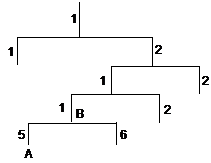
The management information base (MIB) describes the hierarchical architecture of the tree and it is the set defined by the standard variables of the monitored network devices. In the above figure, the managed object B can be uniquely identified by a string of numbers {1.2.1.1}. The number string is the object identifier (OID) of the managed object.
The common MIBs supported by devices are listed in Table 1-1.
|
MIB attribute |
MIB content |
Related RFC |
|
Public MIB |
MIB II based on TCP/IP network device |
RFC 1213 |
|
BRIDGE MIB |
RFC 1493 |
|
|
RFC 2675 |
||
|
RIP MIB |
RFC 1724 |
|
|
RMON MIB |
RFC 2819 |
|
|
Ethernet MIB |
RFC 2665 |
|
|
OSPF MIB |
RFC 1253 |
|
|
IF MIB |
RFC 1573 |
|
|
Private MIB |
DHCP MIB |
— |
|
QACL MIB |
||
|
MSTP MIB |
||
|
VLAN MIB |
||
|
IPV6 ADDRESS MIB |
||
|
MIRRORGROUP MIB |
||
|
QINQ MIB |
||
|
802.x MIB |
||
|
HGMP MIB |
||
|
NTP MIB |
||
|
Device management |
||
|
Interface management |
Configuring Basic SNMP Functions
Because the configuration of SNMPv3 is quite different from that of SNMPv1 and SNMPv2c, their configuration procedures are described in two subsections.
Configuring basic SNMP functions for SNMPv1 or SNMPv2c
Follow these steps to configure basic SNMP functions for SNMPv1 or SNMPv2c:
|
To do… |
Use the command… |
Remarks |
||
|
Enter system view |
system-view |
— |
||
|
Enable SNMP agent |
snmp-agent |
Optional Disabled by default. You can enable SNMP agent by executing this command or any of the commands used to configure SNMP agent. |
||
|
Set system information, and specify to enable SNMPv1 or SNMPv2c on the device |
snmp-agent sys-info { contact sys-contact | location sys-location | version { { v1 | v2c | v3 }* | all } } |
Required By default, the contact information for system maintenance is "Hangzhou, H3C Technology Co., Ltd.", the system location is "Hangzhou China", and the SNMP version is None. |
||
|
Set a community name and access permission |
Direct configuration |
Set a community name |
snmp-agent community { read | write } community-name [ acl acl-number | mib-view view-name ]* |
Required l You can set an SNMPv1/SNMPv2c community name through direct configuration. l Indirect configuration is compatible with SNMPv3. The added user is equal to the community name for SNMPv1 and SNMPv2c. l You can choose either of them as needed. |
|
Indirect configuration |
Set an SNMP group |
snmp-agent group { v1 | v2c } group-name [ read-view read-view ] [ write-view write-view ] [ notify-view notify-view ] [ acl acl-number ] |
||
|
Add a user to an SNMP group |
snmp-agent usm-user { v1 | v2c } user-name group-name [ acl acl-number ] |
|||
|
Set the maximum size of an SNMP packet for SNMP agent to receive or send |
snmp-agent packet max-size byte-count |
Optional 1,500 bytes by default. |
||
|
Set the device engine ID |
snmp-agent local-engineid engineid |
Optional By default, the device engine ID is “enterprise number + device information”. |
||
|
Create/Update the view information |
snmp-agent mib-view { included | excluded } view-name oid-tree [ mask mask-value ] |
Optional By default, the view name is “ViewDefault” and OID is 1. |
||
Configuring basic SNMP functions for SNMPv3
The device now supports the Advanced Encryption Standard (AES) for SNMPv3 to provide encryption. AES can provide higher security than the Data Encryption Standard (DES).
Follow these steps to configure basic SNMP functions for SNMPv3:
|
To do… |
Use the command… |
Remarks |
|
Enter system view |
system-view |
— |
|
Enable SNMP agent |
snmp-agent |
Optional Disabled by default. You can enable SNMP agent by executing this command or any of the commands used to configure SNMP agent. |
|
Set system information and specify to enable SNMPv3 on the device |
snmp-agent sys-info { contact sys-contact | location sys-location | version { { v1 | v2c | v3 }* | all } } |
Required By default, the contact information for system maintenance is "Hangzhou, H3C Technology Co., Ltd.", the system location is "Hangzhou China", and the SNMP version is None. |
|
Set an SNMP group |
snmp-agent group v3 group-name [ authentication | privacy ] [ read-view read-view ] [ write-view write-view ] [ notify-view notify-view ] [ acl acl-number ] |
Required |
|
Encrypt a plain-text password to generate a cipher-text one |
snmp-agent calculate-password plain-password mode { md5 | sha } { local-engineid | specified-engineid engineid } |
Optional This command is used if password in cipher-text is needed for adding a new user. |
|
Add a user to an SNMP group |
snmp-agent usm-user v3 user-name group-name [ cipher ] [ authentication-mode { md5 | sha } auth-password [ privacy-mode { des56 | aes128 } priv-password ] ] [ acl acl-number ] |
Required |
|
Set the maximum size of an SNMP packet for SNMP agent to receive or send |
snmp-agent packet max-size byte-count |
Optional 1,500 bytes by default. |
|
Set the device engine ID |
snmp-agent local-engineid engineid |
Optional By default, the device engine ID is “enterprise number + device information”. |
|
Create or update the view information |
snmp-agent mib-view { included | excluded } view-name oid-tree [ mask mask-value ] |
Optional By default, the view name is “ViewDefault” and OID is 1. |
![]()
The device provides the following functions to prevent attacks through unused UDP ports.
l Executing the snmp-agent command or any of the commands used to configure SNMP agent enables the SNMP agent, and at the same opens UDP port 161 and UDP port 1024 used by SNMP agents and SNMP trap clients respectively.
l Executing the undo snmp-agent command disables the SNMP function and closes UDP port 161 and UDP port 1024 as well.
Configuring Trap Parameters
Configuring Basic Trap
Trap messages refer to those sent by managed devices to the NMS without request. They are used to report some urgent and important events (for example, the rebooting of managed devices).
Note that basic SNMP configuration is performed before you configure basic trap.
Follow these steps to configure basic Trap:
Configuring Extended Trap
The extended Trap includes the following.
l “Interface description” and “interface type” are added into the linkUp/linkDown Trap message. When receiving this extended Trap message, NMS can immediately determine which interface on the device fails according to the interface description and type.
l In all Trap messages sent from the information center to the log server, a MIB object name is added after the OID field of the MIB object. The name is for your better understanding of the MIB object.
Follow these steps to configure extended Trap:
|
To do… |
Use the command… |
Remarks |
|
Enter system view |
system-view |
— |
|
Configure extended Trap |
snmp-agent trap ifmib link extended |
Optional By default, the linkUp/linkDown Trap message adopts the standard format defined in IF-MIB. For details, refer to RFC 1213. |
Enabling Logging for Network Management
Follow these steps to enable logging for network management:
|
To do… |
Use the command… |
Remarks |
|
Enter system view |
system-view |
— |
|
Enable logging for network management |
snmp-agent log { set-operation | get-operation | all } |
Optional Disabled by default. |
![]()
Use the display logbuffer command to view the log of the get and set operations requested by the NMS.
Displaying and Maintaining SNMP
|
To do… |
Use the command… |
Remarks |
|
Display the SNMP information about the current device |
display snmp-agent sys-info [ contact | location | version ]* |
Available in any view |
|
Display SNMP packet statistics |
display snmp-agent statistics |
|
|
Display the engine ID of the current device |
display snmp-agent { local-engineid | remote-engineid } |
|
|
Display group information about the device |
display snmp-agent group [ group-name ] |
|
|
Display SNMP user information |
display snmp-agent usm-user [ engineid engineid | username user-name | group group-name ] |
|
|
Display Trap list information |
display snmp-agent trap-list |
|
|
Display the currently configured community name |
display snmp-agent community [ read | write ] |
|
|
Display the currently configured MIB view |
display snmp-agent mib-view [ exclude | include | viewname view-name ] |
SNMP Configuration Examples
SNMP Configuration Examples
Network requirements
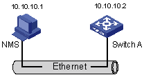
l As shown in Figure 1-2, an NMS and Switch A (SNMP agent) are connected through the Ethernet. The IP address of the NMS is 10.10.10.1 and that of the VLAN interface on Switch A is 10.10.10.2.
l Perform the following configuration on Switch A: setting the community name and access permission, administrator ID, contact and location of Switch A, and enabling the device to sent trap messages.
Thus, the NMS is able to access Switch A and receive the trap messages sent by Switch A.
Figure 1-2 Network diagram for SNMP configuration
Network procedure
# Enable SNMP agent, and set the SNMPv1 and SNMPv2c community names.
<device> system-view
[device] snmp-agent
[device] snmp-agent sys-info version all
[device] snmp-agent community read public
[device] snmp-agent community write private
# Set the access right of the NMS to the MIB of the SNMP agent.
[device] snmp-agent mib-view include internet 1.3.6.1
# For SNMPv3, set:
l SNMPv3 group and user
l security to the level of needing authentication and encryption
l authentication protocol to HMAC-MD5
l authentication password to passmd5
l encryption protocol to AES
l encryption password to cfb128cfb128
[device] snmp-agent group v3 managev3group privacy write-view internet
[device] snmp-agent usm-user v3 managev3user managev3group authentication-mode md5 passmd5 privacy-mode aes128 cfb128cfb128
# Set the VLAN-interface 2 as the interface used by NMS. Add port GigabitEthernet 1/0/2, which is to be used for network management, to VLAN 2. Set the IP address of VLAN-interface 2 as 10.10.10.2.
[device] vlan 2
[device-vlan2] port Ethernet 1/0/2
[device-vlan2] quit
[device] interface Vlan-interface 2
[device-Vlan-interface2] ip address 10.10.10.2 255.255.255.0
[device-Vlan-interface2] quit
# Enable the SNMP agent to send Trap messages to the NMS whose IP address is 10.10.10.1. The SNMP community name to be used is “public”.
[device] snmp-agent trap enable standard authentication
[device] snmp-agent trap enable standard coldstart
[device] snmp-agent trap enable standard linkup
[device] snmp-agent trap enable standard linkdown
[device] snmp-agent target-host trap address udp-domain 10.10.10.1 udp-port 5000 params securityname public
Configuring the NMS
The device supports iMC NMS. SNMPv3 adopts user name and password authentication. When you use the iMC, you need to set user names and choose the security level in. For each security level, you need to set authorization mode, authorization password, encryption mode, encryption password, and so on. In addition, you need to set timeout time and maximum retry times.
You can query and configure the device through the NMS. For more information, refer to the corresponding manuals of network management products.
![]()
Authentication-related configuration on the NMS must be consistent with that of the devices for the NMS to manage the devices successfully.
Introduction to RMON
Remote monitoring (RMON) is a kind of management information base (MIB) defined by Internet Engineering Task Force (IETF). It is an important enhancement made to MIB II standards. RMON is mainly used to monitor the data traffic across a network segment or even the entire network, and is currently a commonly used network management standard.
An RMON system comprises of two parts: the network management station (NMS) and the agents running on network devices. RMON agents operate on network monitors or network probes to collect and keep track of the statistics of the traffic across the network segments to which their ports connect, such as the total number of the packets on a network segment in a specific period of time and the total number of packets successfully sent to a specific host.
l RMON is fully based on SNMP architecture. It is compatible with the current SNMP implementations.
l RMON enables SNMP to monitor remote network devices more effectively and actively, thus providing a satisfactory means of monitoring remote subnets.
l With RMON implemented, the communication traffic between NMS and SNMP agents can be reduced, thus facilitating the management of large-scale internetworks.
Working Mechanism of RMON
RMON allows multiple monitors. It can collect data in the following two ways:
l Using the dedicated RMON probes. When an RMON system operates in this way, the NMS directly obtains management information from the RMON probes and controls the network resources. In this case, all information in the RMON MIB can be obtained.
l Embedding RMON agents into network devices (such as routers, switches and hubs) directly to make the latter capable of RMON probe functions. When an RMON system operates in this way, the NMS collects network management information by exchanging information with the SNMP agents using the basic SNMP commands. However, this way depends on device resources heavily and an NMS operating in this way can only obtain the information about these four groups (instead of all the information in the RMON MIB): alarm group, event group, history group, and statistics group.
The device implements RMON in the second way. With an RMON agent embedded in, the device can serve as a network device with the RMON probe function. Through the RMON-capable SNMP agents running on the device, an NMS can obtain the information about the total traffic, error statistics and performance statistics of the network segments to which the ports of the managed network devices are connected. Thus, the NMS can further manage the networks.
Commonly Used RMON Groups
Event group
Event group is used to define the indexes of events and the processing methods of the events. The events defined in an event group are mainly used by entries in the alarm group and extended alarm group to trigger alarms.
You can specify a network device to act in one of the following ways in response to an event:
l Logging the event
l Sending trap messages to the NMS
l Logging the event and sending trap messages to the NMS
l No processing
Alarm group
RMON alarm management enables monitoring on specific alarm variables (such as the statistics of a port). When the value of a monitored variable exceeds the threshold, an alarm event is generated, which then triggers the network device to act in the way defined in the events. Events are defined in event groups.
With an alarm entry defined in an alarm group, a network device performs the following operations accordingly:
l Sampling the defined alarm variables periodically
l Comparing the samples with the threshold and triggering the corresponding events if the former exceed the latter
Extended alarm group
With extended alarm entry, you can perform operations on the samples of alarm variables and then compare the operation results with the thresholds, thus implement more flexible alarm functions.
With an extended alarm entry defined in an extended alarm group, the network devices perform the following operations accordingly:
l Sampling the alarm variables referenced in the defined extended alarm expressions periodically
l Performing operations on the samples according to the defined expressions
l Comparing the operation results with the thresholds and triggering corresponding events if the operation result exceeds the thresholds.
History group
After a history group is configured, the device collects network statistics information periodically and stores the statistics information temporarily for later use. A history group can provide the history data of the statistics on network segment traffic, error packets, broadcast packets, and bandwidth utilization.
With the history data management function, you can configure network devices to collect history data, sample and store data of a specific port periodically.
Statistics group
Statistics group contains the statistics of each monitored port on the device. An entry in a statistics group is an accumulated value counting from the time when the statistics group is created.
The statistics include the number of the following items: collisions, packets with cyclic redundancy check (CRC) errors, undersize (or oversize) packets, broadcast packets, multicast packets, and received bytes and packets.
With the RMON statistics management function, you can monitor the use of a port and make statistics on the errors occurred when the ports are being used.
RMON Configuration
Before performing RMON configuration, make sure the SNMP agents are correctly configured. For the information about SNMP agent configuration, refer to Configuring Basic SNMP Functions.
Follow these steps to configure RMON:
|
Use the command… |
Remarks |
|
|
Enter system view |
system-view |
— |
|
Add an event entry |
rmon event event-entry [ description string ] { log | trap trap-community | log-trap log-trapcommunity | none } [ owner text ] |
Optional |
|
Add an alarm entry |
rmon alarm entry-number alarm-variable sampling-time { delta | absolute } rising_threshold threshold-value1 event-entry1 falling_threshold threshold-value2 event-entry2 [ owner text ] |
Optional Before adding an alarm entry, you need to use the rmon event command to define the event to be referenced by the alarm entry. |
|
Add an extended alarm entry |
rmon prialarm entry-number prialarm-formula prialarm-des sampling-timer { delta | absolute | changeratio } rising_threshold threshold-value1 event-entry1 falling_threshold threshold-value2 event-entry2 entrytype { forever | cycle cycle-period } [ owner text ] |
Optional Before adding an extended alarm entry, you need to use the rmon event command to define the event to be referenced by the extended alarm entry. |
|
Enter Ethernet port view |
interface interface-type interface-number |
— |
|
Add a history entry |
rmon history entry-number buckets number interval sampling-interval [ owner text ] |
Optional |
|
Add a statistics entry |
rmon statistics entry-number [ owner text ] |
Optional |
![]()
l The rmon alarm and rmon prialarm commands take effect on existing nodes only.
l For each port, only one RMON statistics entry can be created. That is, if an RMON statistics entry is already created for a given port, you will fail to create another statistics entry with a different index for the same port.
Displaying and Maintaining RMON
|
To do… |
Use the command… |
Remarks |
|
Display RMON statistics |
display rmon statistics [ interface-type interface-number | unit unit-number ] |
Available in any view |
|
Display RMON history information |
display rmon history [ interface-type interface-number | unit unit-number ] |
|
|
Display RMON alarm information |
display rmon alarm [ entry-number ] |
|
|
Display extended RMON alarm information |
display rmon prialarm [ prialarm-entry-number ] |
|
|
Display RMON events |
display rmon event [ event-entry ] |
|
|
Display RMON event logs |
display rmon eventlog [ event-entry ] |
RMON Configuration Examples
Network requirements
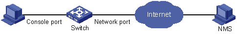
l As shown in Figure 2-1, the Switch to be tested is connected to a remote NMS through the Internet. Ensure that the SNMP agents are correctly configured before performing RMON configuration.
l Create an entry in the extended alarm table to monitor the information of statistics on the Ethernet port, if the change rate of which exceeds the set threshold, the alarm events will be triggered.
Figure 2-1 Network diagram for RMON configuration
Configuration procedures
# Add the statistics entry numbered 1 to take statistics on GigabitEthernet 1/0/1.
<device> system-view
[device] interface GigabitEthernet 1/0/1
[device-GigabitEthernet1/0/1] rmon statistics 1
[device-GigabitEthernet1/0/1] quit
# Add the event entries numbered 1 and 2 to the event table, which will be triggered by the following extended alarm.
[device] rmon event 1 log
[device] rmon event 2 trap 10.21.30.55
# Add an entry numbered 2 to the extended alarm table to allow the system to calculate the alarm variables with the (.1.3.6.1.2.1.16.1.1.1.9.1+.1.3.6.1.2.1.16.1.1.1.10.1) formula to get the numbers of all the oversize and undersize packets received by GigabitEthernet 1/0/1 that are in correct data format and sample it in every 10 seconds. When the change ratio between samples reaches the rising threshold of 50, event 1 is triggered; when the change ratio drops under the falling threshold, event 2 is triggered.
[device] rmon prialarm 2 (.1.3.6.1.2.1.16.1.1.1.9.1+.1.3.6.1.2.1.16.1.1.1.10.1) test 10 changeratio rising_threshold 50 1 falling_threshold 5 2 entrytype forever owner user1
# Display the RMON extended alarm entry numbered 2.
[device] display rmon prialarm 2
Prialarm table 2 owned by user1 is VALID.
Samples type : changeratio
Variable formula : (.1.3.6.1.2.1.16.1.1.1.9.1+.1.3.6.1.2.1.16.1.1.1.10.1)
Description : test
Sampling interval : 10(sec)
Rising threshold : 100(linked with event 1)
Falling threshold : 10(linked with event 2)
When startup enables : risingOrFallingAlarm
This entry will exist : forever.
Latest value : 0