- Table of Contents
-
- H3C SecPath M9000-AI-E8[E16] Multi Service Security Gateway Series Installation Guides-6W101
- 00-Preface
- 01-Chapter 1 Chassis views
- 02-Chapter 2 Preparing for Installation
- 03-Chapter 3 Installing the Gateway
- 04-Chapter 4 Accessing the Gateway and Configuring Basic Settings
- 05-Chapter 5 Troubleshooting
- 06-Chapter 6 Replacing Removable Components
- 07-Appendix A FRUs and Compatibility Matrixes
- 08-Appendix B Technical Specifications
- 09-Appendix C LEDs
- 10-Appendix D Cables
- 11-Appendix E Slot arrangement and interface numbering
- 12-Appendix F Engineering labels
- 13-Appendix G Cabling Recommendations
- 14-Appendix H Repackaging the Gateway
- Related Documents
-
| Title | Size | Download |
|---|---|---|
| 13-Appendix G Cabling Recommendations | 473.34 KB |
Appendix G Cabling recommendations
Routing cables
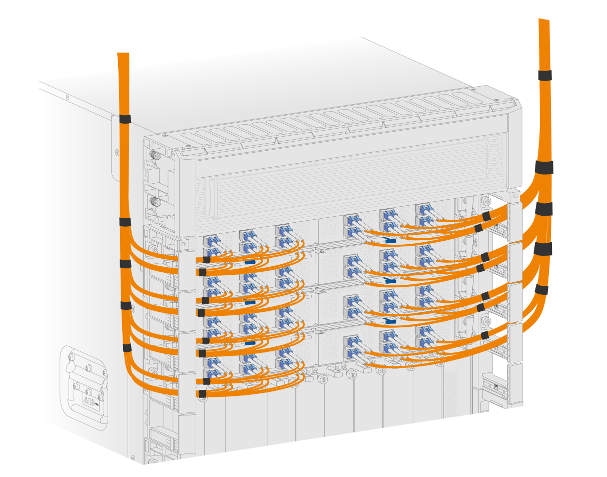
The cable management brackets are installed on the two sides of the front panel of the gateway. As a best practice, route cables from the left and right sides of the gateway, as shown in Figure 1.
Figure 1 Routing cables (M9000-AI-E16)
Routing power cords
When you route power cords, take consideration of the layout of the equipment room, including the locations of the power distribution cabinet, AC power receptacles, and lightning protection box. Place all re-connecting facilities, such as receptacles, at the rack bottom (Do not place them at a location out of the rack and easy to reach.)
The power supplies are located at the rear panel of the gateway. As a best practice, route power cords from the left and right of the rear panel.
General cabling requirements
Minimum curvature radius of cables
· The curvature radius of an attached power cord, communication cable, or ribbon cable should be at least five times the cable’s outer diameter. If the cable is frequently bent, plugged and unplugged, the curvature radius should be at least seven times the cable's outer diameter.
· The curvature radius of an ordinary attached coaxial cable should be at least seven times of the cable's outer diameter. If the coaxial cable is frequently bent, plugged and unplugged, the curvature radius should be at least 10 times the cable's outer diameter.
Minimum curvature radius of fibers
· When the fiber is wrapped up around the cabling plate, the diameter of the cabling plate should be at least 25 times the fiber's diameter.
· When the fiber is being moved, the curvature radius of the fiber should be at least 20 times the fiber's diameter.
· When the fiber is attached, the curvature radius of the fiber should be at least 10 times the fiber's diameter.
|
|
NOTE: The fiber's diameter refers to the outer diameter of the fiber jacket. Typically, the diameter of a single-core fiber is 0.9 mm (0.04 in), 2.0 mm (0.08 in), or 3.0 mm (0.12 in). |
Prerequisites
Label cables before you route or bundle them.
Cable management guidelines
When you route and bundle up cables, follow these guidelines:
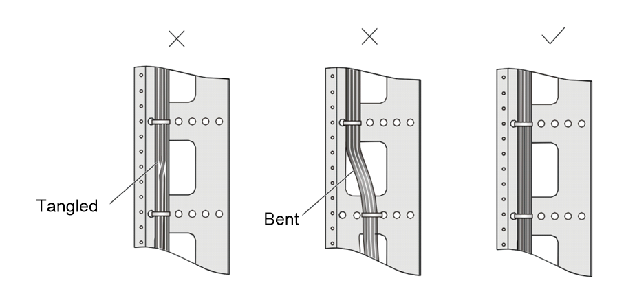
· Bind and route the cables neatly inside the rack, and make sure they are not kinked or bent.
Figure 2 Correct and incorrect cable binding
· The cable bend radius at connectors must be at least 5 times the cable diameter, and must be at least twice the cable diameter away from the connectors.
· Route different types of cables (for example, power cords and signal cables) separately. If they are close to one another, cross them over one another. If you route them in parallel, make sure the space between a power cord bundle and a signal cable bundle is at least 30 mm (1.18 in).
· The cable management brackets and cable routing slots, inside or outside the rack, are smooth and have no sharp edges or tips.
· When you route cables through sharp sheet metal penetration points or along sharp edges of mechanical parts, use bushings or take any other action to protect the cables from being cut or abraded. The sheet metal penetration points must be smooth and fully rounded.
· Use the correct type of ties to bind the cables. Do not bind cables with joined ties. The following types of ties are available: 100 × 2.5 mm (3.94 × 0.10 in), 150 × 3.6 mm (5.91 × 0.14 in), 300 × 3.6 mm (11.81 × 0.14 in), 530 × 9 mm (20.87 × 0.35 in), and 580 × 13 mm (22.83 × 0.51 in).
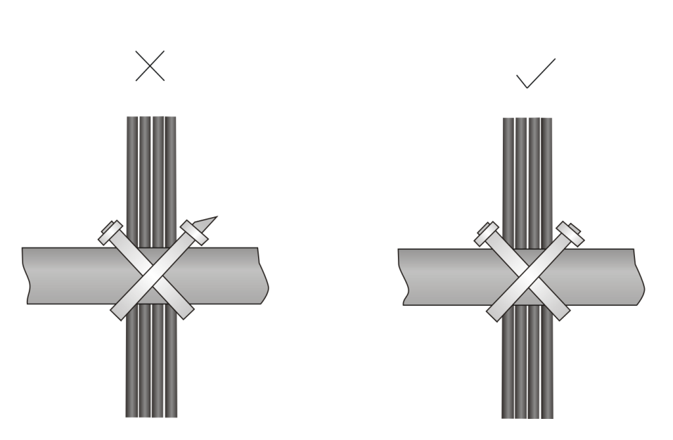
· After binding the cables, cut the excess from the ties, leaving no sharp or angular tips. See Figure 3.
Figure 3 Cutting cable ties
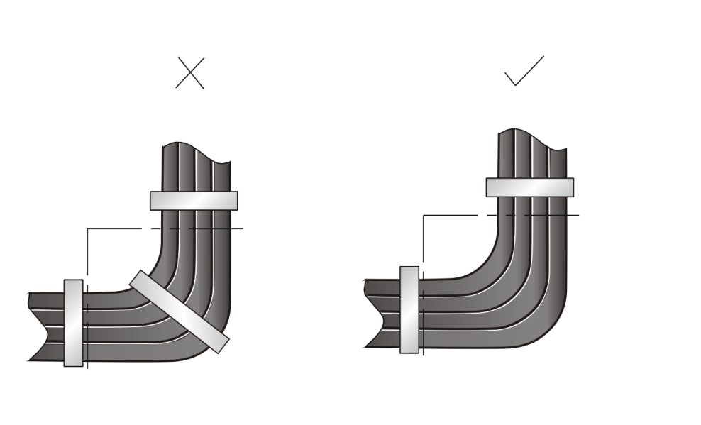
· When you bend cables, bind them as shown in Figure 4. To avoid excessive stress causing cable core break, do not tie up the cables in the bending area.
Figure 4 Binding cables where they must be bent
· Route, bind, and attach excess cables for easy, safe maintenance activities and correct operations.
· Do not tie power cords to slide rails.
· When you connect a cable to an articulated part, for example, when you connect a grounding cable to a cabinet door, leave enough slack in cables and make sure they are not stressed from any movement of the part.
· Cables must be protected at points where they might rub or come in contact with sharp edges or heated areas. Use high temperature cables near heat sources.
· Securely fasten cables and take adequate measures to prevent loose connections.
Figure 5 Securely fastening cables

|
(1) Flat washer |
(2) Spring washer |
(3) Nut |
· Fasten heavy or rigid power cords at the connectors to relief stress.
· Do not use tapping screws to fasten the connecting terminals.
· Bind together cables that are the same type and routed in the same direction.
Table 1 lists the cable bundling specifications.
Table 1 Tie-binding parameters
|
Cable bundle diameter (mm) |
Space between bundles (mm) |
|
10 |
80 to 150 |
|
10 to 30 |
150 to 200 |
|
30 |
200 to 300 |
· Do not tie cables or bundles in a knot.
· The metal parts of the crimped cold-pressed terminal blocks (such as circuit breaker) cannot protrude beyond the blocks.
