- Table of Contents
-
- H3C SecPath M9000-AI-E8[E16] Multi Service Security Gateway Series Installation Guides-6W101
- 00-Preface
- 01-Chapter 1 Chassis views
- 02-Chapter 2 Preparing for Installation
- 03-Chapter 3 Installing the Gateway
- 04-Chapter 4 Accessing the Gateway and Configuring Basic Settings
- 05-Chapter 5 Troubleshooting
- 06-Chapter 6 Replacing Removable Components
- 07-Appendix A FRUs and Compatibility Matrixes
- 08-Appendix B Technical Specifications
- 09-Appendix C LEDs
- 10-Appendix D Cables
- 11-Appendix E Slot arrangement and interface numbering
- 12-Appendix F Engineering labels
- 13-Appendix G Cabling Recommendations
- 14-Appendix H Repackaging the Gateway
- Related Documents
-
| Title | Size | Download |
|---|---|---|
| 03-Chapter 3 Installing the Gateway | 3.24 MB |
Confirming installation preparations
Attaching slide rails to the rack
Removing the air filter and top hood
Mounting the gateway in a rack
Installing an air filter and a top hood
Installing cable management brackets
Installing cable management brackets for an M9000-AI-E8 gateway
Installing cable management brackets for an M9000-AI-E16 gateway
Installing supervisor engine modules
Installing switching fabric modules
Installing interface modules or service modules
Installing interface switch modules or AI security engine modules
Installing HVDC power supplies
Installing transceiver modules and fiber cables
(Optional) Installing air filter doors
Installing the gateway
Confirming installation preparations
Before you install the gateway, verify that:
· You have read the chapter "Preparing for installation" carefully and the installation site meets all the requirements.
· A 19-inch rack has been installed.
· The rack is sturdy and securely grounded.
· The rack has enough space to install the gateway and no debris exists inside or around the rack.
· The mounting position of the gateway on the rack has been identified. As a best practice, install the gateway at the bottom of the rack.
· The total height of the devices to be installed in the rack is no higher than the available installation height of the rack and enough clearance is reserved for cable routing. Make sure the heaviest device is placed at the bottom of the rack.
· The gateway is ready for installation and has been carried to a place near the rack and convenient for moving.
Installation flowchart
Figure 1 Installation flowchart

Rack-mounting the gateway
|
|
CAUTION: The gateway is heavy. For rack stability, install it at a lowest possible position. |
Attaching slide rails to the rack
Attach the required slide rails to the rack before you mount the gateway in the rack. For more information about attaching slide rails, see the slide rails installation guide.
Make sure the slide rail installation positions are at the same height on the four rack posts.
Table 1 Slide rail requirements
|
Gateway model |
Max. chassis weight (full configuration) |
Applicable slide rails |
||
|
Slide rail model |
Adjustment range |
Occupied space |
||
|
M9000-AI-E8 |
87.4 kg (192.68 lb) |
LSVM1BSR10 |
630 to 900 mm (24.80 to 35.43 in) |
1 RU |
|
M9000-AI-E16 |
187.2 kg (412.70 lb) |
LSXM1BSR |
630 to 900 mm (24.80 to 35.43 in) |
1 RU |
Removing the air filter and top hood
Only the M9000-AI-E16 gateway has an air filter and a top hood.
To remove the air filter and top hood:
1. Wear an ESD wrist strap and make sure it is reliably grounded.
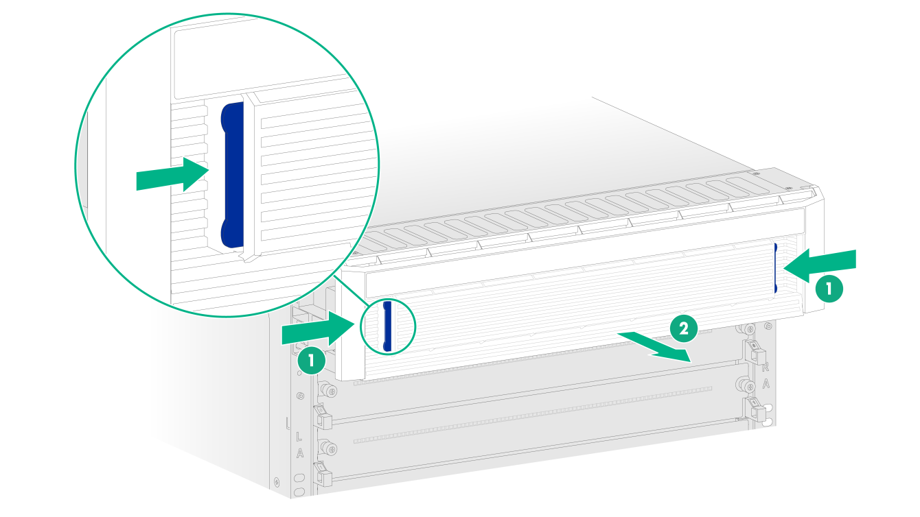
2. Press the locking tabs at both sides of the air filter to remove the air filter from the top hood.
Figure 2 Removing the air filter
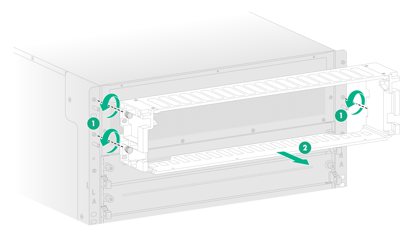
3. Use a Phillips screwdriver to loosen the captive screws and remove the top hood.
Figure 3 Removing the top hood
Removing a fan tray
Remove the fan trays when you rack-mount the M9000-AI-E16 gateway.
The gateway is heavy. As a best practice, remove all fan trays from the chassis before rack-mounting the gateway.
To remove a fan tray:
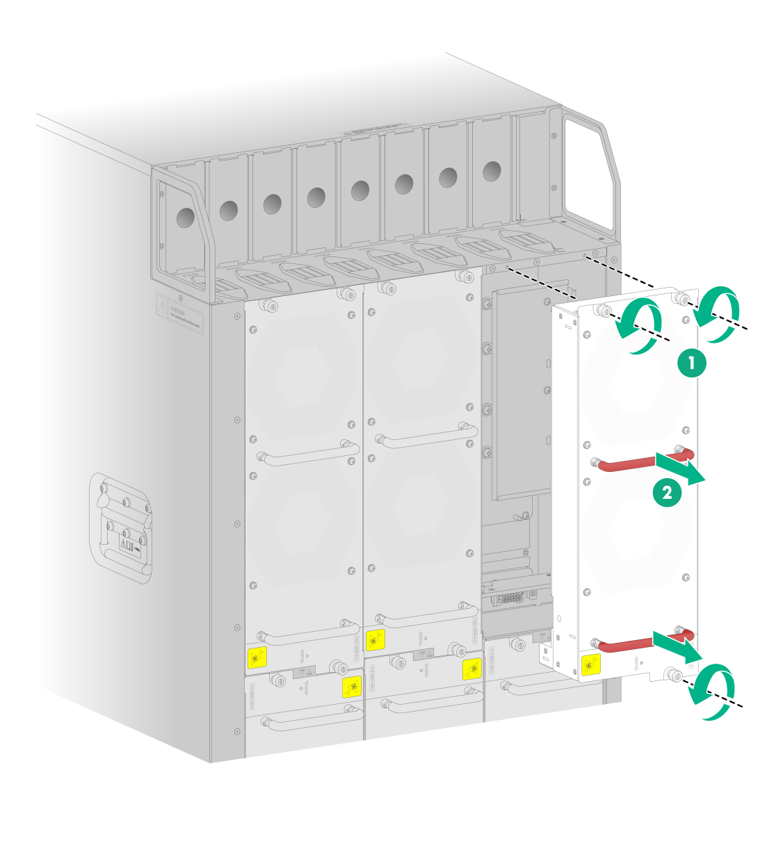
1. Wear an ESD wrist strap and make sure it is reliably grounded.
2. Loosen the captive screws by using a Phillips screwdriver.
3. Hold the fan tray handle and then pull the fan tray out of the chassis slowly.
4. Put the removed fan tray on an anti-static mat.
Figure 4 Removing a fan tray (M9000-AI-E16 gateway)
Mounting the gateway in a rack
|
|
CAUTION: · When you move the gateway to a low temperature environment from a high temperature environment, condensation might occur. Before installing the gateway, please dry the gateway to prevent the internal components from being damaged because of short circuit. · As a best practice, remove the fan trays from the chassis. If you are not to remove the fan trays, do not hold the handle of a fan tray to move the gateway. Any attempt to carry the gateway by this part might cause equipment damage or even bodily injury. · After you place the gateway on the slide rails, do not leave go of your hands immediately because this might tip the gateway, damaging the gateway or even causing bodily injury. |
To mount the gateway in a rack:
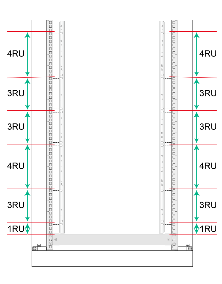
1. Determine the cage nut installation holes according to the holes in the mounting brackets, as shown in Figure 5. Mark the cage nut installation holes on the front rack post.
The mounting brackets have been installed in the chassis. You can use other tools, such as a tape measure, to align the holes in the mounting brackets with the holes on the rack posts and mark the cage nut installation holes.
Figure 5 Marking cage nut installation holes (M9000-AI-E16 gateway)
2. Install cage nuts in the marked square holes on the front rack posts.
Figure 6 Installing the cage nuts
3. Align the rear of the chassis with the front of the rack.
4. Use multiple people (at least four people as a best practice) to lift the gateway by holding the chassis handles.
5. Place the gateway on the slide rails from front of the rack. Slide the gateway along the guide rails until the mounting brackets on the gateway come into contact with the front rack posts.
6. Use screws provided with the gateway to secure the gateway to the rack posts.
Figure 7 Mounting the gateway in a rack (M9000-AI-E16 gateway)
Installing an air filter and a top hood
|
|
IMPORTANT: The M9000-AI-E16 gateway supports air filter doors. If you have ordered air filter doors, first install the air filter doors and then install an air filter and a top hood on the M9000-AI-E16 gateway. |
Only the M9000-AI-E16 gateway supports air filters and top hoods.
To install an air filter and top hood:
1. Align the holes in the top hood with the pins on the mounting bracket. Push the top hood so that the pins enter the holes in the top hood.
2. Fasten the captive screws to secure the top hood.
Figure 8 Installing a top hood

3. Position the air filter over the top hood, and then push the air filter until it is seated into the top hood.
Figure 9 Installing an air filter
Grounding the gateway
|
|
CAUTION: · Reliably grounding the gateway is crucial to lightning protection and EMI protection. Ground the gateway reliably with the grounding cable provided with the gateway. · Connect the grounding cable to the earthing system in the equipment room. Do not connect it to a fire main or lightning rod. |
To ground the gateway:
1. Unpack the grounding cable.
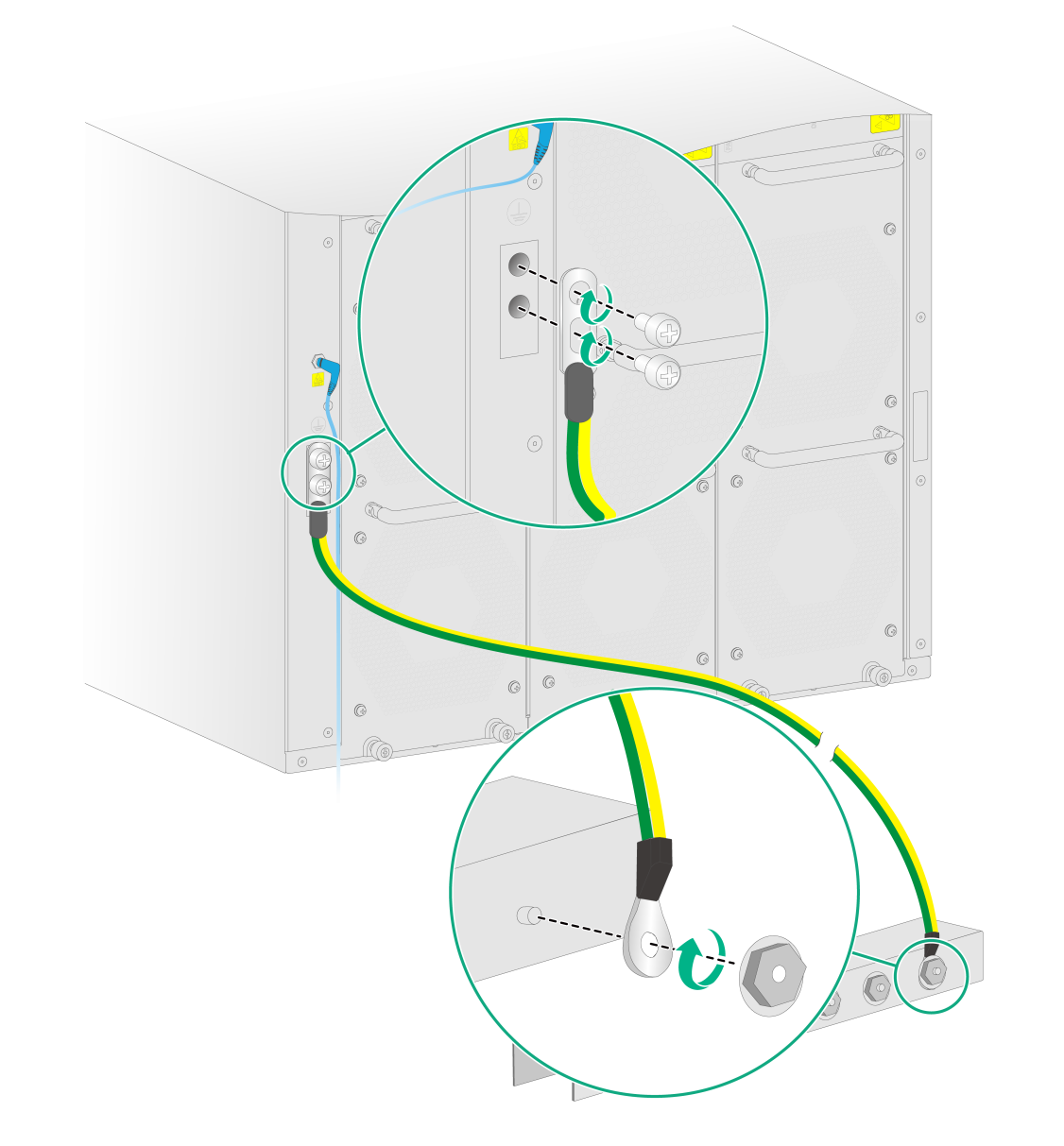
2. Remove the grounding screws from the grounding holes at the rear of the chassis.
3. Use grounding screws to attach the two-hole grounding lug of the grounding cable to the chassis.
4. Connect the ring terminal of the grounding cable to a grounding post of the grounding strip, and fasten the grounding cable to the grounding strip with the hex nut.
Figure 10 Connecting the grounding cable to a grounding strip (M9000-AI-E16 gateway)
Installing cable management brackets
Installing cable management brackets for an M9000-AI-E8 gateway
The cable management brackets have been installed on the two sides of an M9000-AI-E8 gateway when the gateway is shipped. You only need to attach the cable guides to the cable management bracket.
Installing cable management brackets for an M9000-AI-E16 gateway
Install cable management brackets after you mount the gateway in the rack.
The gateway comes with three types of cable management brackets LA, LB/RB, and RA and two types of cable guides LA and RA.
Figure 11 Cable management brackets

The installation procedure is similar for cable management brackets at the left side and at the right side. The following installs a cable management bracket at the right side.
To install a cable management bracket:
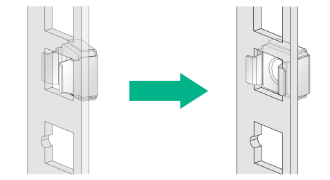
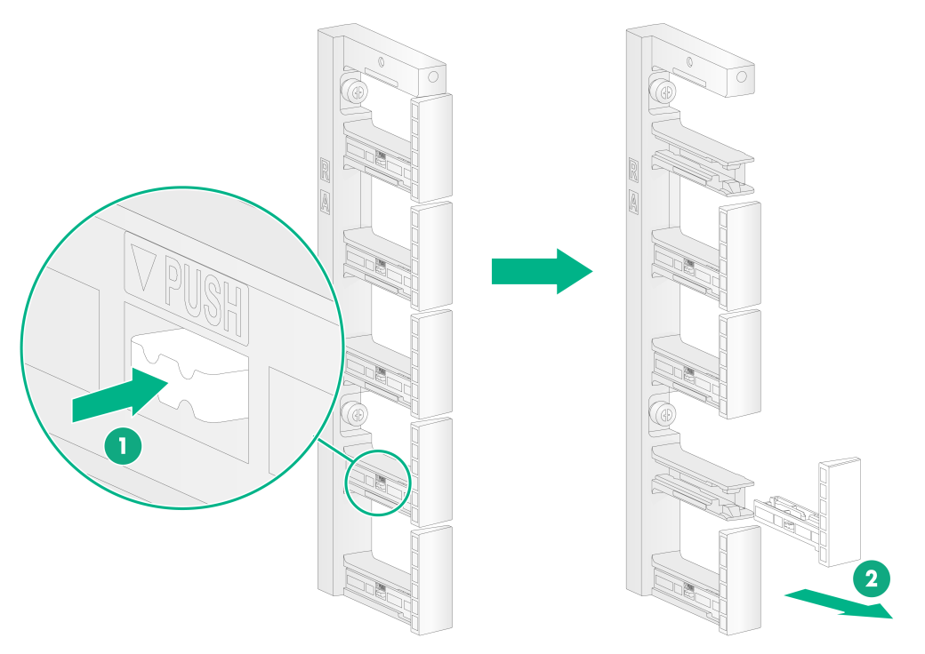
1. If any cable guide hinders installation of the cable management bracket, press the tab on the cable guide and then remove the cable guide from the cable management bracket.
Figure 12 Removing a cable guide
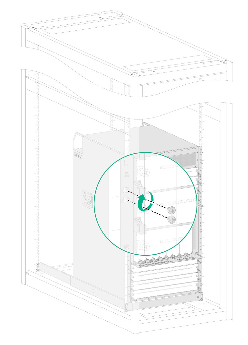
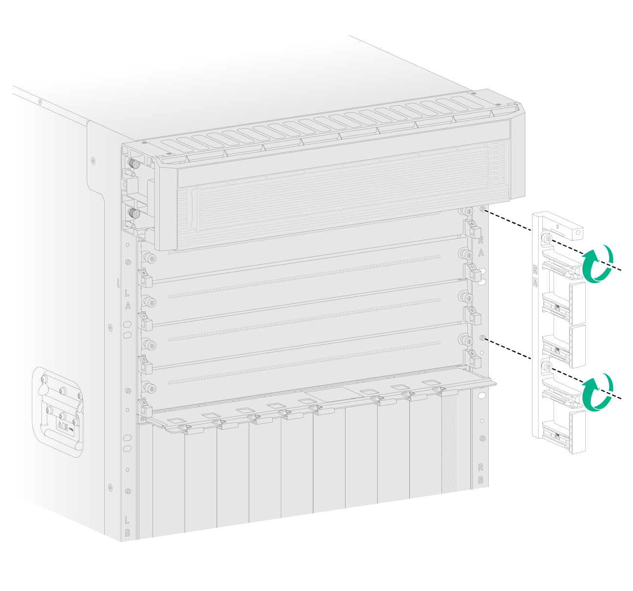
2. Orient the cable management bracket, with the lettering facing upward, and then position the cable management bracket on the mounting bracket.
3. Align the captive screws on the cable management bracket with the holes in the mounting bracket. Fasten the captive screws to secure the cable management bracket.
Figure 13 Installing a cable management bracket
4. Install the removed cable guide (if any) to the cable management bracket.
Installing modules
Installing supervisor engine modules
|
|
CAUTION: · The gateway supports active/standby supervisor engine module (SEM) switchover when you install two SEMs for the gateway. For the standby SEM to operate correctly, make sure the active and standby SEMs are the same model. · If you install two SEMs for the gateway, you can hot swap the standby SEM. If you install only one SEM for the gateway, you cannot hot swap that SEM. · If you are not to install a SEM in a SEM slot, keep the filler panel in the slot. |
The gateway has two SEM slots. You can install one SEM, or two SEMs in 1+1 redundancy for the gateway.
Installing a SEM for an M9000-AI-E8 gateway
1. Wear an ESD wrist strap and make sure the wrist strap is reliably grounded.
2. Loosen the captive screws on the filler panel and remove it from the target SEM slot.
3. Correctly orient the SEM and then push the SEM steadily into the slot along the guide rails.
4. Rotate the handle downward. Make sure the SEM makes close contact with the backplane.
5. Fasten the captive screws on the SEM.
Figure 14 Installing a SEM for an M9000-AI-E8 gateway
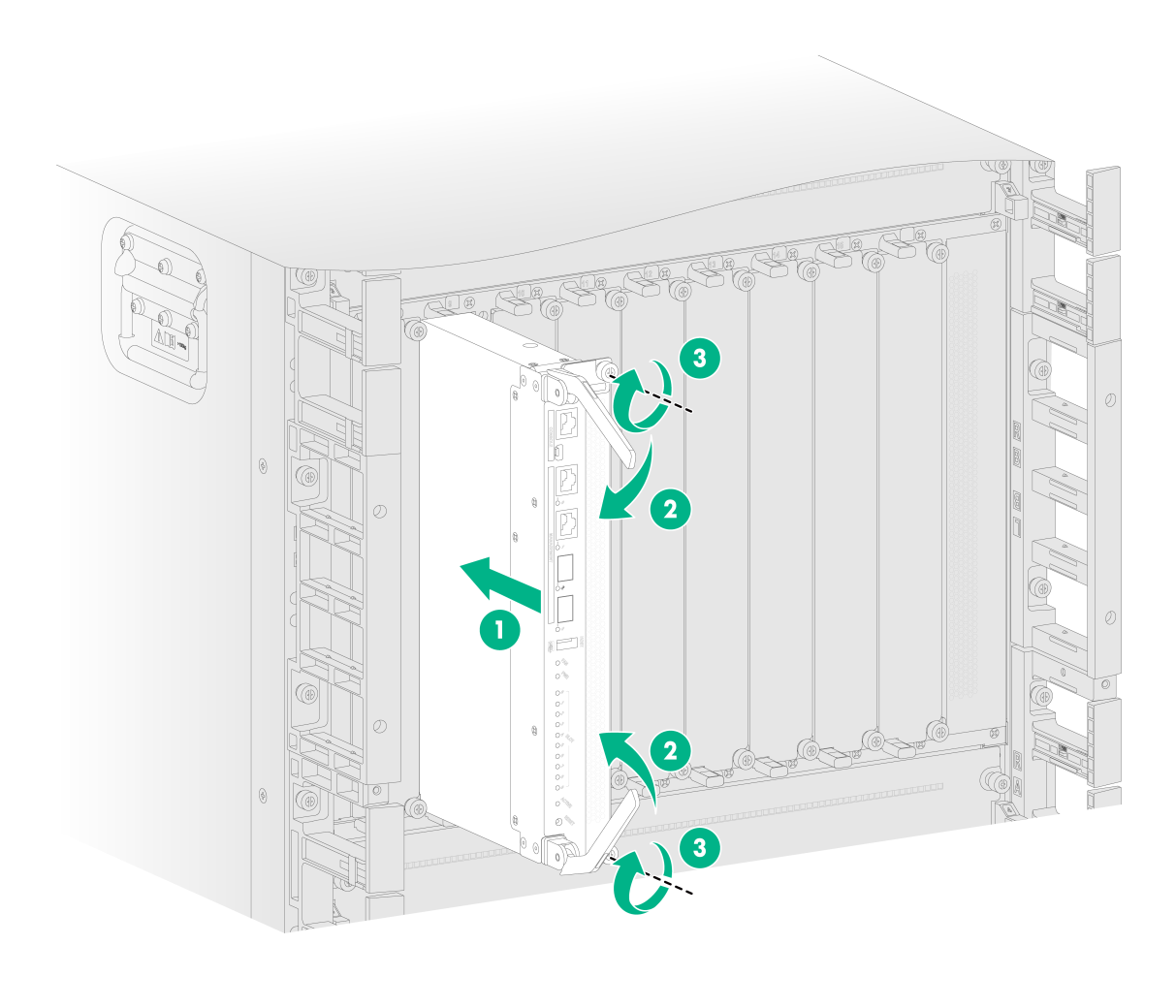
Installing a SEM for an M9000-AI-E16 gateway
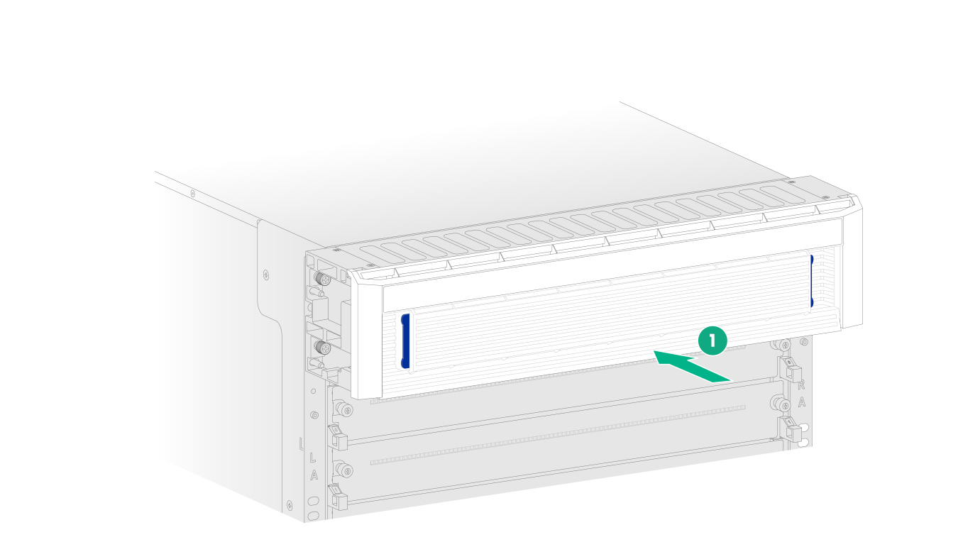
1. Wear an ESD wrist strap and make sure the wrist strap is reliably grounded.
2. Remove the filler panel from the target SEM slot. Keep the removed filler panel secure for future use.
Figure 15 Removing the filler panel
3. Correctly orient the SEM, insert it into the slot, and then push it steadily into the slot along the guide rails.
4. Fully open the ejector levers of the SEM.
5. Continue to push the SEM by its front panel until the ejector levers make close contact with the slot edges.
6. Close the ejector levers until they come in close contact with the front panel.
7. Fasten the captive screws on the SEM.
Figure 16 Installing a SEM for an M9000-AI-E16 gateway
Installing switching fabric modules
|
|
CAUTION: · Only the NSQM5FAB16A1 switching fabric module is hot swappable. · The M9000-AI-E8 gateway provides four switching fabric module slots. Only slots 6 and 7 are available for installing switching fabric modules. Both of the slots must be installed with switching fabric modules. · The M9000-AI-E16 gateway provides four switching fabric module slots. Only slots 10 and 11 are available for installing switching fabric modules. You can install one switching fabric module or two switching fabric modules for 1+1 redundancy. · When you install a switching fabric module, avoid damaging the connectors on it. |
Installing a switching fabric module for an M9000-AI-E8 gateway
1. Face the rear panel of the gateway and remove the filler panel from the target slot. Keep the removed filler panel secure for future use.
2. Press the locking tabs of the ejector levers to release the levers.
3. Correctly orient the switching fabric module. Align the switching fabric module with the target slot and insert it into the slot along the guide rails. Then fully open the ejector levers.
4. Continue to push the switching fabric module by its front panel until the ejector levers make close contact with the slot edges.
5. Close the ejector levers until the locking tabs lock the ejector levers in place.
Figure 17 Installing a switching fabric module for an M9000-AI-E8 gateway
Installing a switching fabric module for an M9000-AI-E16 gateway
1. Place the switching fabric module on a workbench and remove the protection box from the connector side of the switching fabric module.
Figure 18 Removing the protection box
2. Remove the filler panel from the target switching fabric module slot. Keep the removed filler panel secure for future use.
3. Install the switching fabric module. The installation procedure is similar for switching fabric modules and SEMs. For more information about installing the switching fabric module, see "Installing a SEM for an M9000-AI-E16 gateway."
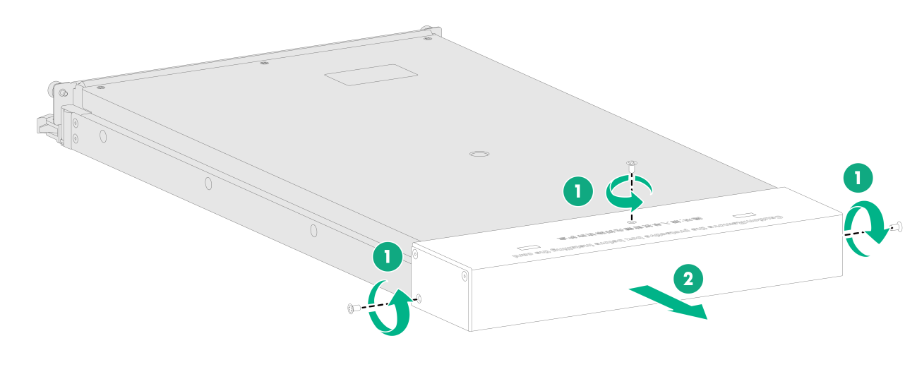
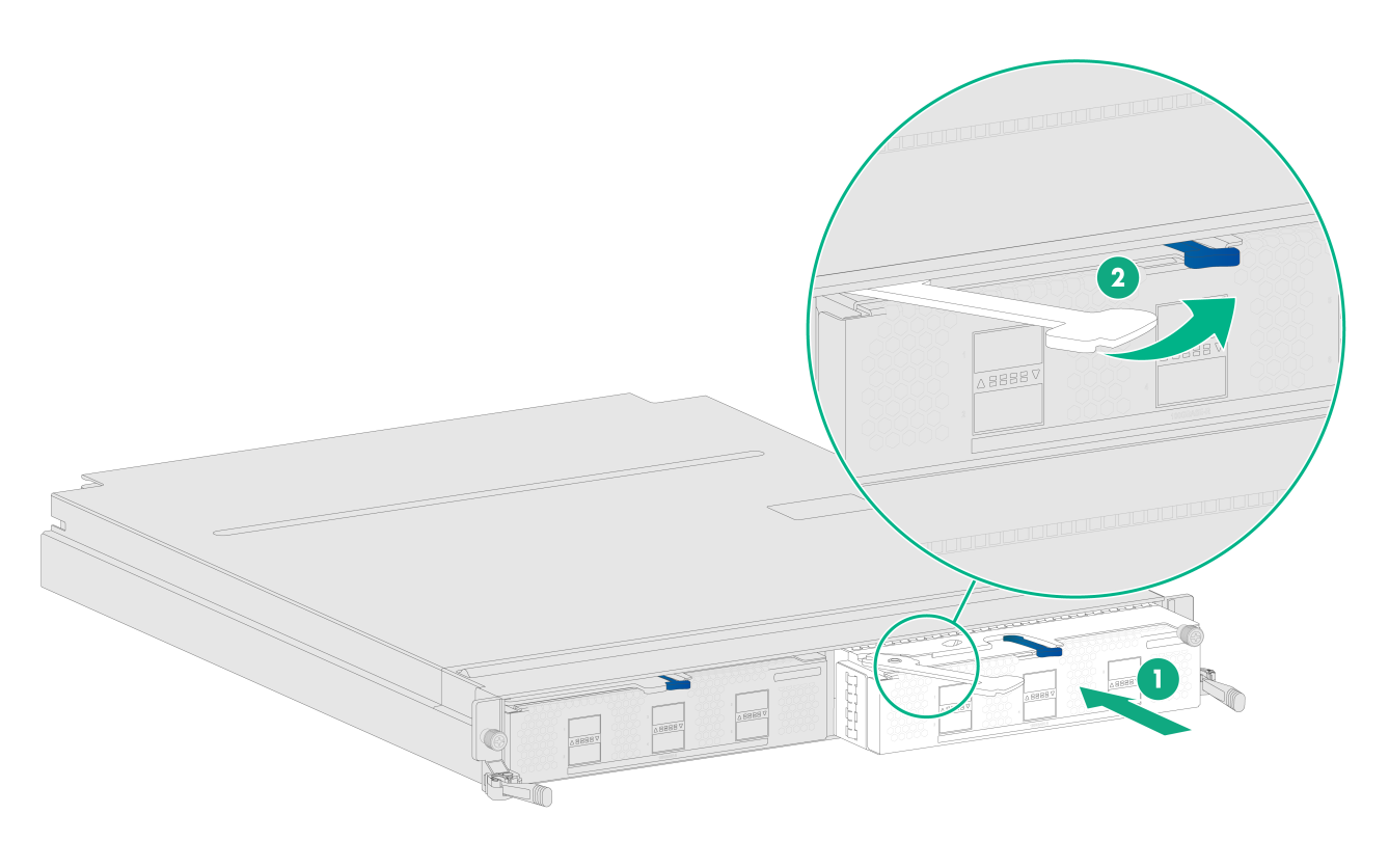
Installing interface modules or service modules
|
|
CAUTION: · The interface modules and service modules are not hot swappable. To install an interface module or service module on the gateway, first install it on an interface switch module and then install the interface switch module on the gateway. · If you are not to install an interface module or service module in a slot on an interface switch module, keep the filler panel in the slot. |
The procedure is the same for installing an interface module and service module on an interface switch module. The following installs an interface module.
To install an interface module on an interface switch module:
1. Wear an ESD wrist strap and make sure the wrist strap is reliably grounded.
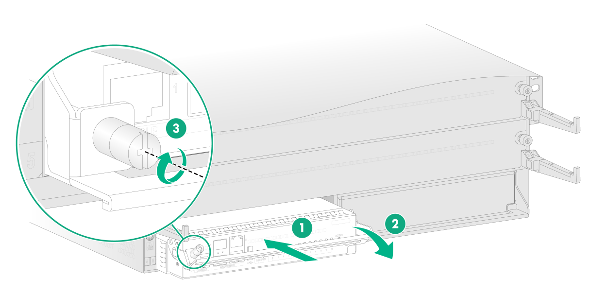
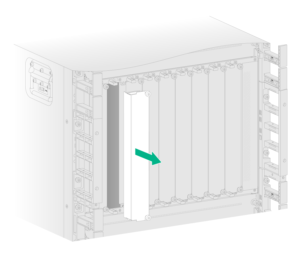
2. Remove the filler panel from the target slot. Put your forefinger and thumb into the hole of the filler panel, press the metal tab in the left hole, and then pull the filler panel out.
3. Open the ejector lever on the interface module and then push the module slowly into the slot along the guide rails until you cannot push it any further.
4. Close the ejector lever until the latch locks the ejector lever in place.
Figure 19 Installing an interface module on an interface switch module (M9000-AI-E16 gateway)
5. Install the interface switch module in the gateway. For more information about installing the interface switch module, see "Installing interface switch modules or AI security engine modules."
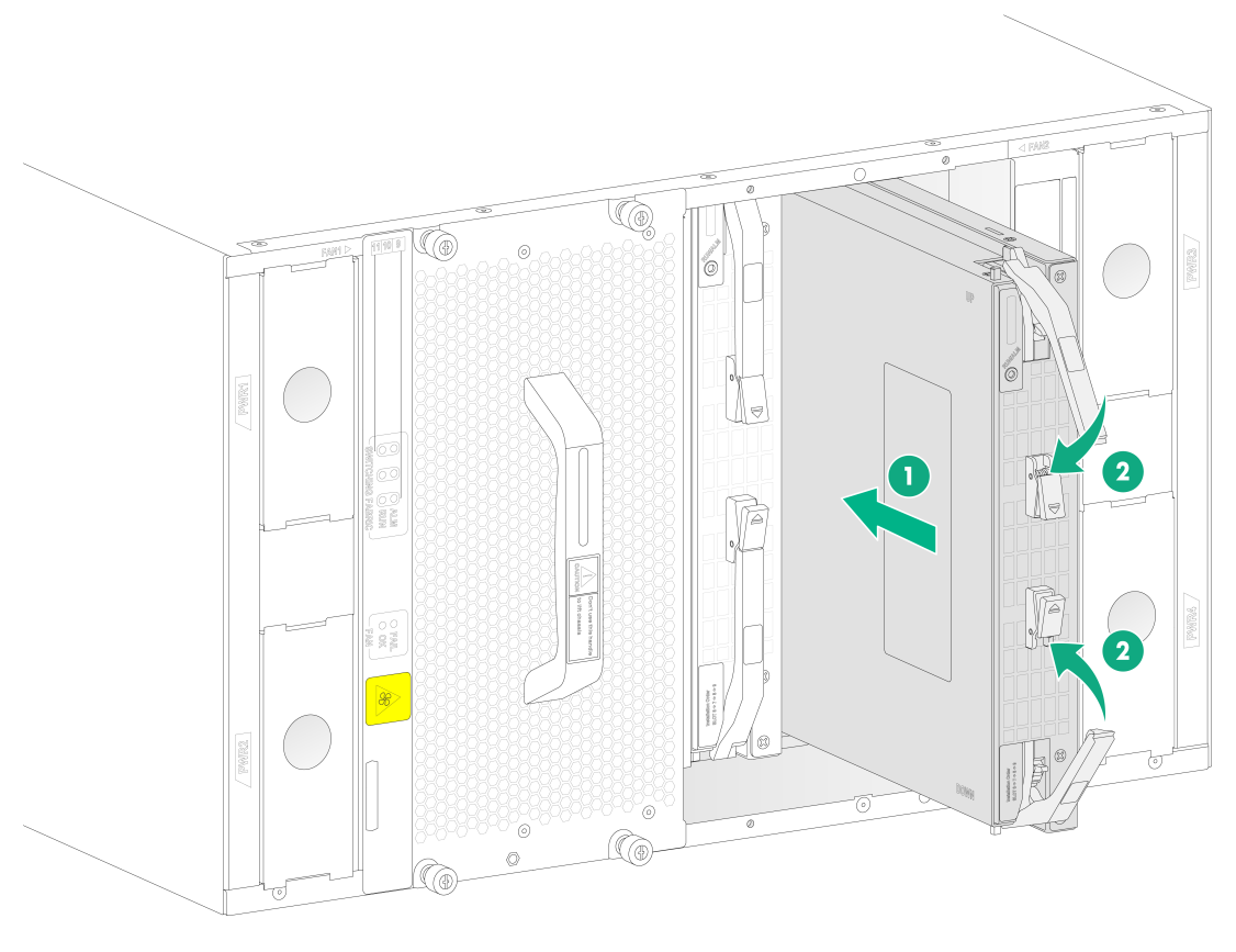
Installing interface switch modules or AI security engine modules
|
|
CAUTION: · The interface switch modules are hot swappable. · The NSQM5AIASKA1 and NSQM5AIASKB1 AI security engine modules are hot swappable. · If you are not to install an interface switch module in an interface switch module slot, keep the filler panel in the slot. |
The procedure is the same for installing an AI security engine module and interface switch module. The following installs an interface switch module.
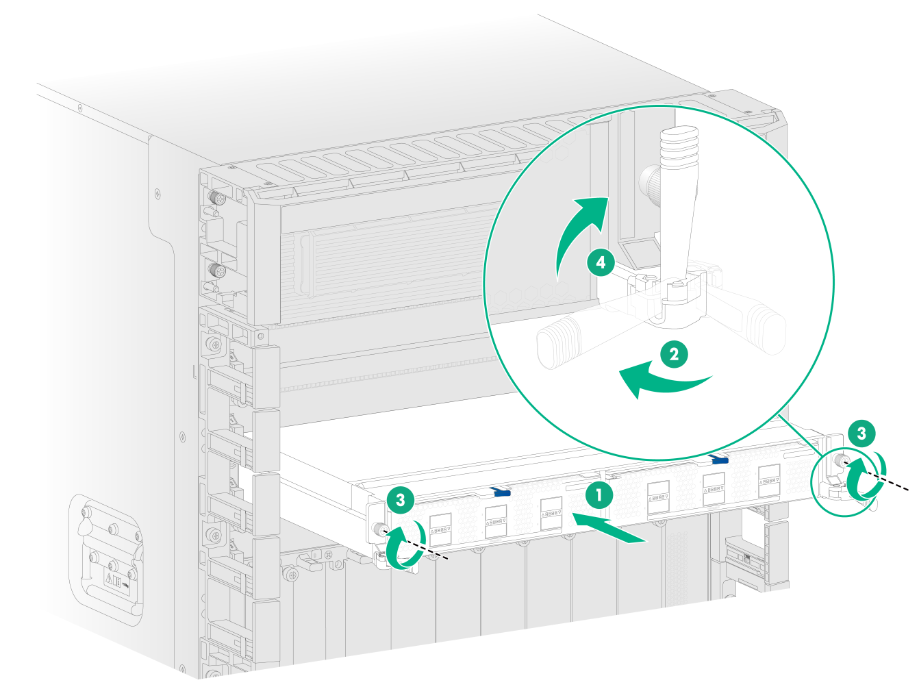
To install an interface switch module:
1. Wear an ESD wrist strap and make sure the wrist strap is reliably grounded.
2. Remove the filler panel from the target interface switch module slot (service module slot). Keep the removed filler panel secure for future use.
3. Pivot down and fully open the ejector levers of the module. Gently push the module into the slot along the guide rails.
4. Continue to push the module by its front panel until you cannot push it any further. Then close the ejector levers.
5. Use a Phillips screwdriver to fasten the captive screws on the module.
6. Pivot up the ejector levers on the module.
Figure 20 Installing the interface switch module (M9000-AI-E16)
Installing fan trays
An M9000-AI-E8 gateway has two fan tray slots and supports 1+1 fan tray redundancy. As a best practice, install two fan trays for the gateway. To install a fan tray in slot FAN1, orient the fan tray with the LEDs on the left side of the front panel. To install a fan tray in slot FAN2, orient the fan tray with the LEDs on the right side of the front panel.
An M9000-AI-E16 gateway has six fan tray slots in two rows and supports 5+1 fan tray redundancy. As a best practice, install six fan trays for the gateway. To install a fan tray in a slot in the upper row, orient the fan tray with the LED at the bottom. To install a fan tray in a slot in the lower row, orient the fan tray with the LED at the top.
To install a fan tray:
1. Wear an ESD wrist strap and make sure the wrist strap is reliably grounded.
2. Correctly orient the fan tray and align the fan tray with the fan tray slot.
3. Holding the fan tray handles, steadily insert the fan tray way into the slot. Keep the fan tray as steady as possible while inserting it into the slot.
4. Fasten the captive screws on the fan tray.
Figure 21 Installing a fan tray (M9000-AI-E16 gateway)
Installing power supplies
Installing DC power supplies
Available DC power supplies
The PSR2400-54D DC power supply is available for the gateway.
Table 2 PSR2400-54D power supply specifications
|
Item |
Specifications |
|
Rated input voltage |
–48 VDC to –60 VDC |
|
Input voltage |
–40 VDC to –72 VDC |
|
Maximum input current |
80 A |
|
Rated output voltage |
54 VDC |
|
Maximum output current |
44.5 A |
|
Maximum output power |
2400 W |
DC power supply configuration guidelines
Determine the number of DC power supplies based on the system power consumption and the DC power supply configuration based on the power input mode.
· Make sure the total output power of the power supplies is greater than the system power consumption (with a 20% power surplus as a best practice).
· As a best practice, configure N+M (M ≥ 1) DC power supply redundancy. Make sure N+M is not larger than the total number of power supply slots.
N is the number of DC power supplies.
· Provide a circuit breaker or fuse for power input of each DC power supply. Make sure each input line has a current carrying capacity not less than 100 A.
Installing a DC power supply
On an M9000-AI-E8 gateway, the power supply slots are located on both sides of the rear panel. To install the power supply in a left power supply slot, orient the power supply with the latch above the handle. To install the power supply in a right power supply slot, orient the power supply with the latch below the handle.
On an M9000-AI-E16 gateway, the power supply slots are located at the top of the rear panel. Make sure the latch is above the handle when you install the power supply.
The following procedure installs a DC power supply on an M9000-AI-E16 gateway.
To install a DC power supply:
1. Put your forefinger into the hole in the filler panel and pull out the filler panel along the guide rails.
Figure 22 Removing a filler panel (M9000-AI-E16 gateway)
2. Correctly orient the power supply.
3. Align the power supply with the power supply slot. Then slide the power supply along the guide rails into the slot until the latch locks the power supply in place.
Figure 23 Installing a power supply (M9000-AI-E16 gateway)
Connecting a DC power cord
|
|
WARNING! Before you connect a DC power cord, make sure the circuit breakers for both of the positive and negative power input wires are turned off. |
To connect a DC power cord:
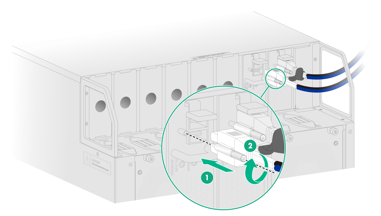
1. Connect the DC power cord connector to the DC input receptacle of the power supply.
2. Fasten the screw on the connector to secure the connector to the receptacle.
3. Connect the other ends of the DC power cords to a DC power source, with the positive wire (+) to the positive terminal and the negative wire (-) to the negative terminal.
Figure 24 Connecting a DC power cord (M9000-AI-E16 gateway)
Installing AC power supplies
Available AC power supplies
The PSR2400-54A, PSR3000-54A, and PSR3000-54AHD AC power supplies are available for the gateway. Table 3, Table 4, and Table 5 describe the specifications of PSR2400-54A, PSR3000-54A , and PSR3000-54AHD AC power supplies, respectively.
Table 3 PSR2400-54A power supply specifications
|
Item |
Specifications |
|
Rated input voltage |
· 100 VAC to 130 VAC @ 50 or 60 Hz · 200 VAC to 240 VAC @ 50 or 60 Hz |
|
Input voltage |
90 VAC to 264 VAC @ 47 or 63 Hz |
|
Rated input current |
16 A |
|
Rated output voltage |
54 VDC |
|
Maximum output current |
44.5 A |
|
Maximum output power |
· 100 VAC to 130 VAC @ 60 Hz: 1200 W · 200 VAC to 240 VAC @ 50 Hz: 2400 W |
Table 4 PSR3000-54A power supply specifications
|
Item |
Specifications |
|
Rated input voltage |
· 100 VAC to 240 VAC @ 50 or 60 Hz (AC input) · 240 VDC (high-voltage DC input) |
|
Input voltage |
· 90 VAC to 290 VAC @ 47 or 63 Hz (AC input) · 190 VDC to 300 VDC (high-voltage DC input) |
|
Rated input current |
16 A |
|
Rated output voltage |
54 VDC |
|
Maximum output current |
55.6 A |
|
Maximum output power |
· 100 VAC to 130 VAC @ 60 Hz: 1500 W · 200 VAC to 240 VAC @ 50 Hz: 3000 W · 240 VDC: 3000 W |
Table 5 PSR3000-54AHD power supply specifications
|
Item |
Specifications |
|
Rated input voltage |
· 100 VAC to 240 VAC @ 50 or 60 Hz (AC input) · 240 VDC to 380 VDC (high-voltage DC input) |
|
Input voltage |
· 90 VAC to 290 VAC @ 47 or 63 Hz (AC input) · 180 VDC to 400 VDC (high-voltage DC input) |
|
Rated input current |
20 A |
|
Rated output voltage |
54 VDC |
|
Maximum output current |
44.5 A |
|
Maximum output power |
· 100 VAC to 130 VAC @ 60 Hz: 1500 W · 200 VAC to 240 VAC @ 50 Hz: 3000 W · 240 VDC to 380 VDC: 3000 W |
AC power supply configuration guidelines
Determine the number of AC power supplies based on the system power consumption and the AC power supply configuration based on the power input mode.
· Make sure the total output power of the power supplies is greater than the system power consumption (with a 20% power surplus as a best practice).
· As a best practice, configure N+M (M ≥ 1) AC power supply redundancy. Make sure N+M is not larger than the total number of power supply slots.
N is the number of AC power supplies.
· Provide a circuit breaker for power input of each AC power supply. Make sure each circuit breaker has a current rating not less than 20 A.
Installing an AC power supply
On an M9000-AI-E8 gateway, the power supply slots are located on both sides of the rear panel. To install the power supply in a left power supply slot, orient the power supply with the latch above the handle. To install the power supply in a right power supply slot, orient the power supply with the latch below the handle.
On an M9000-AI-E16 gateway, the power supply slots are located at the top of the rear panel. Make sure the latch is above the handle when you install the power supply.
The following procedure installs an AC power supply on an M9000-AI-E16 gateway.
To install an AC power supply:
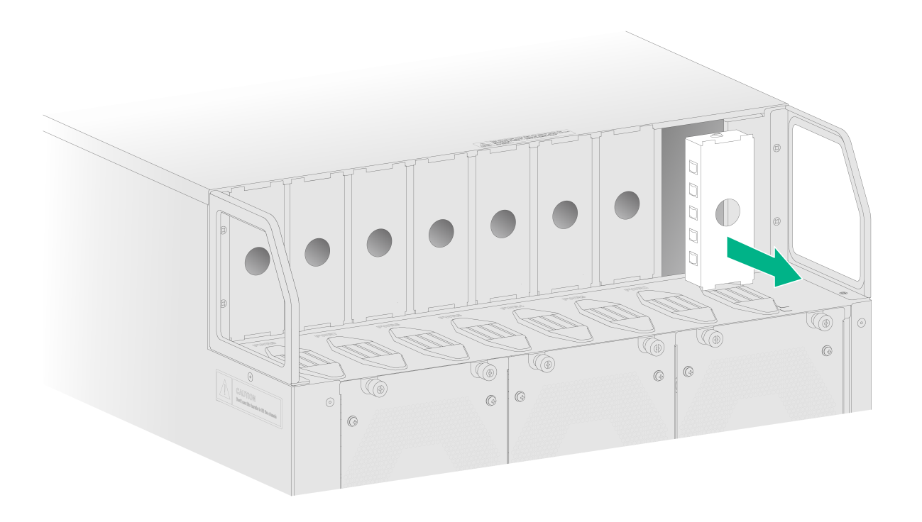
1. Put your forefinger into the hole in the filler panel and pull out the filler panel along the guide rails.
Figure 25 Removing a filler panel (M9000-AI-E16 gateway)

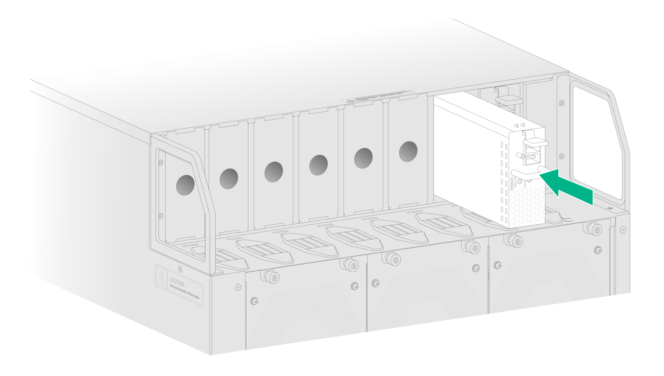
2. Correctly orient the power supply.
3. Align the power supply with the power supply slot. Then slide the power supply along the guide rails into the slot until the latch locks the power supply in place.
Figure 26 Installing an AC power supply (M9000-AI-E16 gateway)

Connecting an AC power cord
|
|
WARNING! · Make sure each power cord has a separate circuit breaker. · Before you connect a power cord, turn off the circuit breaker for it. |
To connect an AC power cord:
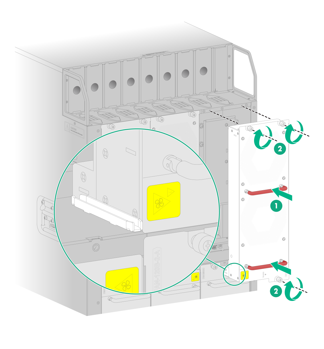
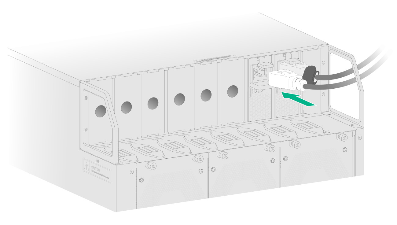
1. Connect the AC power cord connector to the AC input receptacle of the power supply.
2. Connect the other end of the power cord to an AC power source.
Figure 27 Connecting an AC power cord (M9000-AI-E16 gateway)
Installing HVDC power supplies
The PSR3000-54AHD power supply supports AC input and HVDC input and is available for the gateway for HVDC input. See Table 5 for the PSR3000-54AHD power supply specifications.
HVDC power supply configuration guidelines
Determine the number of HVDC power supplies based on the system power consumption and the HVDC power supply configuration based on the power input mode.
· As a best practice, configure N+N (dual power sources) HVDC power supply redundancy. Make sure N+N is not larger than the total number of power supply slots.
N is the number of HVDC power supplies.
· Make sure the total output power of the power supplies is greater than the system power consumption (with a 20% power surplus as a best practice).
· Provide a circuit breaker for power input of each HVDC power supply. Make sure each circuit breaker has a current rating not less than 20 A and meets the requirements for HVDC power supply, such as HVDC certification and bipolar protection.
Installing an HVDC power supply
The installation procedure is the same for HVDC and AC power supplies. For information about installing a PSR3000-54AHD power supply, see "Installing AC power supplies."
Connecting an HVDC power cord
The connecting procedure is the same for HVDC and AC power cords. For information about connecting the power cord for a PSR3000-54AHD power supply, see "Connecting an AC power cord."
Installing transceiver modules and fiber cables
|
|
WARNING! Disconnected optical fibers or transceiver modules might emit invisible laser light. Do not stare into beams or view directly with optical instruments when the gateway is operating. |
|
|
CAUTION: · Before installing a transceiver module, remove the fiber cables, if any, from it. For more information about installing transceiver modules, see the installation guide for the transceiver modules. · If you are not to use a fiber port or transceiver module, insert dust plugs into the port or module. If you are not to connect an optical fiber, install dust caps for the fiber connector. |
To install a transceiver module and fiber cable:
1. Wear an ESD wrist strap and make sure the wrist strap is reliably grounded.
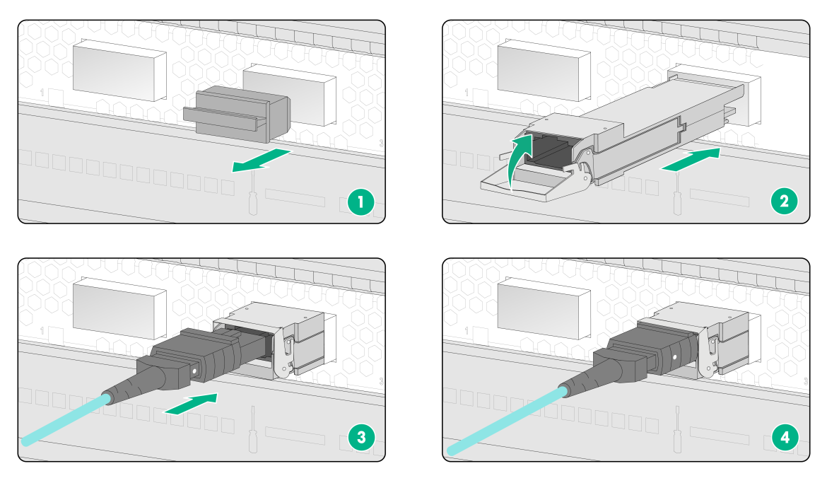
2. Remove the dust plug from the target fiber port.
3. Pull the bail latch on the transceiver module upwards.
Skip this step if the bail latch is plastic.
4. Take the transceiver module by its two sides and push the end without the bail latch gently into the port until it is firmly seated in the fiber port.
5. Remove the dust plug and dust cap from the transceiver module and fiber connector, respectively.
6. Connect the fiber cable to the transceiver module.
¡ LC connector—Align the connector with the transceiver module and push it into the transceiver module slightly until it clicks into place.
¡ MPO connector—Orient the connector with the white spot on it facing right. Insert the MPO fiber connector horizontally into the transceiver module. Push the MPO fiber connector into the transceiver module slightly until it clicks into place.
7. Use cable ties to bind fiber cables every 150 mm (5.91 in).
8. Label fiber cables according to the cable labeling specifications.
Figure 28 Installing a transceiver module and fiber cable (with LC fiber connector)
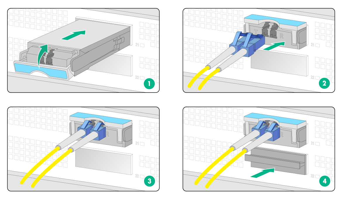
Figure 29 Installing a transceiver module and fiber cable (with MPO fiber connector)
(Optional) Installing air filter doors
The M9000-AI gateway supports air filter doors. For more information about installing air filter doors, see the installation guide for the air filter doors.
Verifying the installation
Table 6 Post-installation checklist
|
Item |
Requirements |
|
Installation site |
· No condensation on the surface of the gateway or inside of the gateway. · Keep the gateway clean and dust free. · No packing boxes, packing bags or other packing materials left in the installation site. · Keep the air inlet and outlet vents of the gateway free of obstruction. |
|
Gateway |
· All modules are installed correctly. · No slot is empty. Each is installed with a module or filler panel, · Fan trays are installed correctly. |
|
Cables |
· The gateway is grounded reliably with the provided grounding cable. Both ends of the grounding cable are securely connected. · No switch or fuse is installed on the grounding cable. · The power cords are connected reliably and no short circuit has occurred in power input and output. · Power cords, grounding cables and fiber cables are routed and bound separately. · The cables are bound neatly with cable ties at an even distance. · The cable labels are correct, clear, and affixed to the cable in the same direction. |
|
Electricity safety |
· A circuit breaker is provided for each power input line. · The circuit breaker is switched off before you connect the power cord to a power module, |
Power-on check
|
|
WARNING! Locate the emergency power-off switch in the room before power-on so you can quickly shut power off when an electrical accident occurs. |
|
|
CAUTION: Before powering on the gateway, make sure all fan trays are present. |
Power-on check flowchart
Figure 30 Power-on check flowchart
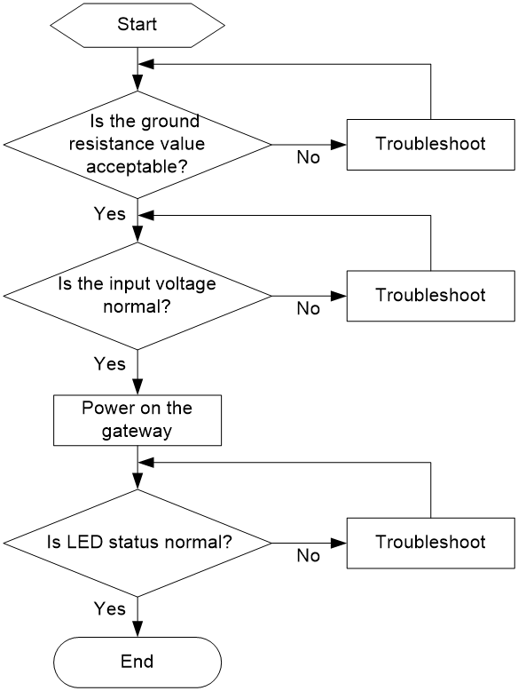
The gateway provides LEDs for modules installed on the gateway to indicate their operating status. For more information about LEDs, see "Appendix C LEDs."
