- Table of Contents
-
- H3C SecPath M9000-AI-E8[E16] Multi Service Security Gateway Series Installation Guides-6W101
- 00-Preface
- 01-Chapter 1 Chassis views
- 02-Chapter 2 Preparing for Installation
- 03-Chapter 3 Installing the Gateway
- 04-Chapter 4 Accessing the Gateway and Configuring Basic Settings
- 05-Chapter 5 Troubleshooting
- 06-Chapter 6 Replacing Removable Components
- 07-Appendix A FRUs and Compatibility Matrixes
- 08-Appendix B Technical Specifications
- 09-Appendix C LEDs
- 10-Appendix D Cables
- 11-Appendix E Slot arrangement and interface numbering
- 12-Appendix F Engineering labels
- 13-Appendix G Cabling Recommendations
- 14-Appendix H Repackaging the Gateway
- Related Documents
-
| Title | Size | Download |
|---|---|---|
| 06-Chapter 6 Replacing Removable Components | 1.42 MB |
Contents
Replacing removable components
Replacing a switching fabric module
Replacing an interface switch module or AI security engine module
Replacing an interface module or service module
Replacing a transceiver module
Replacing removable components
|
|
CAUTION: · To avoid device damage or bodily injury, strictly follow the procedures provided in this chapter for component replacement. · Long-time exposure to strong air flow might cause discomfort. To avoid this hazard, do not stand close to the air outlet vents while the switch is operating. If you must be next to the switch on the air outlet vent side for an extended period, avoid the air flow or take other protective measures. |
The gateway uses a modular architecture. You can replace the removable components on it.
Replacing a module
|
|
CAUTION: · If you are not to install a new module in a slot after removing the old one, install a filler panel in the slot for adequate heat dissipation and dust prevention. · Before removing a module, first remove the cables from it. |
Replacing a SEM
|
|
CAUTION: When two SEMs are installed on the gateway, you can hot swap the SEM in standby mode directly. If only one SEM is installed on the gateway, you cannot hot swap the SEM. To replace the only SEM on the gateway, you must power off the gateway first. |
Replacing a SEM for an M9000-AI-E8 gateway
1. Prepare an antistatic mat for placing the removed supervisor engine module (SEM).
2. Wear an ESD wrist strap, and make sure it makes good skin contact and is reliably grounded.
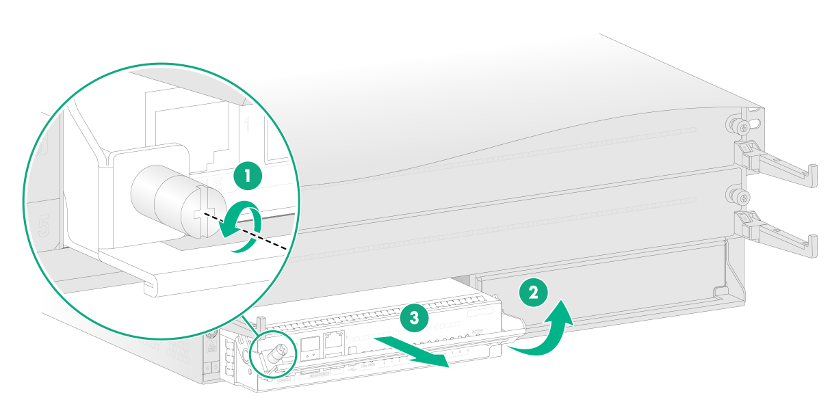
3. Use a Phillips screwdriver to loosen the captive screw on the left of the module.
4. Pivot up the handle of the module and then pull the module slowly out of the slot.
5. Place the removed module on the antistatic mat.
6. Install a new SEM. For the installation procedure, see "Installing the gateway."
Figure 1 Removing a SEM from an M9000-AI-E8 gateway
Replacing a SEM for an M9000-AI-E16 gateway
1. Prepare an antistatic mat for placing the removed SEM.
2. Wear an ESD wrist strap, and make sure it makes good skin contact and is reliably grounded.
3. Use a Phillips screwdriver to loosen the captive screws on the module.
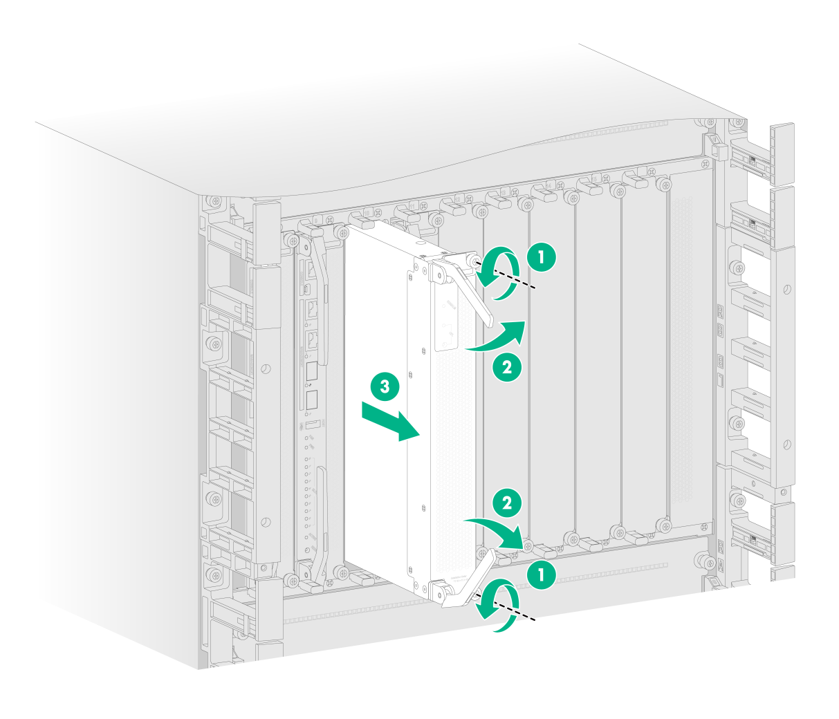
4. Open the two ejector levers of the module simultaneously to disengage the module from the backplane. Then pull the module slowly out of the slot.
5. Place the removed module on the antistatic mat.
6. Install a new SEM. For the installation procedure, see "Installing the gateway."
Figure 2 Removing a SEM from an M9000-AI-E16 gateway
Replacing a switching fabric module
Replacing a switching fabric module for an M9000-AI-E8 gateway
|
|
CAUTION: You cannot hot swap switching fabric modules on an M9000-AI-E8 gateway. To replace a switching fabric module for an M9000-AI-E8 gateway, first power off the gateway. |
To replace a switching fabric module:
1. Prepare an antistatic mat for placing the removed switching fabric module.
2. Wear an ESD wrist strap, and make sure it makes good skin contact and is reliably grounded.
3. Remove the fan tray above the switching fabric module.
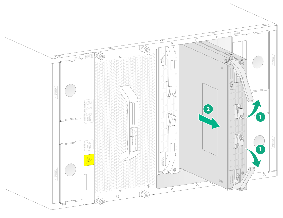
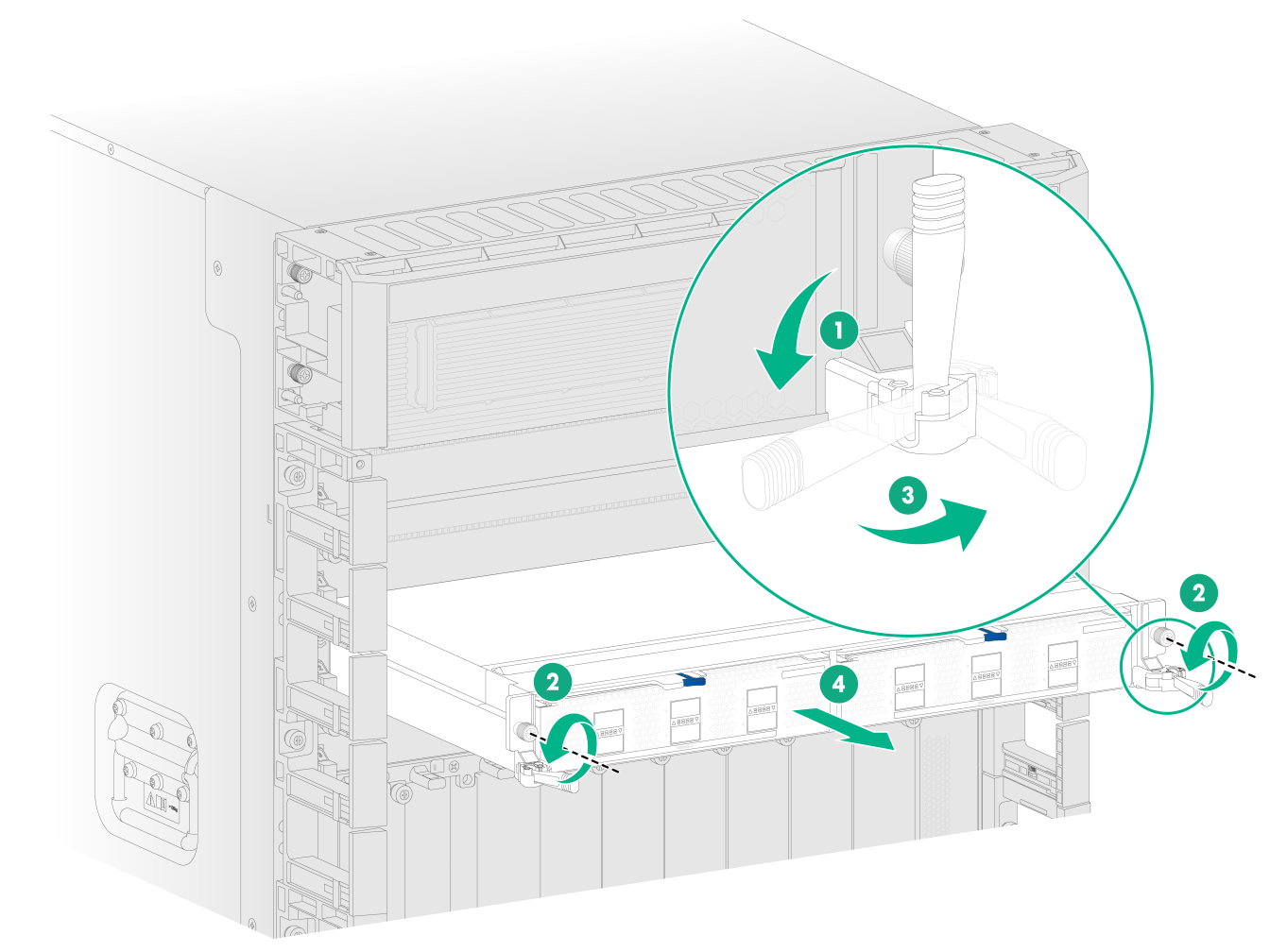
4. Press the release latches on the module to release the ejector levers. Open the two ejector levers of the module simultaneously to disengage the module from the backplane. Then pull the module slowly out of the slot.
5. Place the removed module on the antistatic mat.
6. Install a new switching fabric module. For the installation procedure, see "Installing the gateway."
7. Reinstall the fan tray.
Figure 3 Removing a switching fabric module from an M9000-AI-E8 gateway
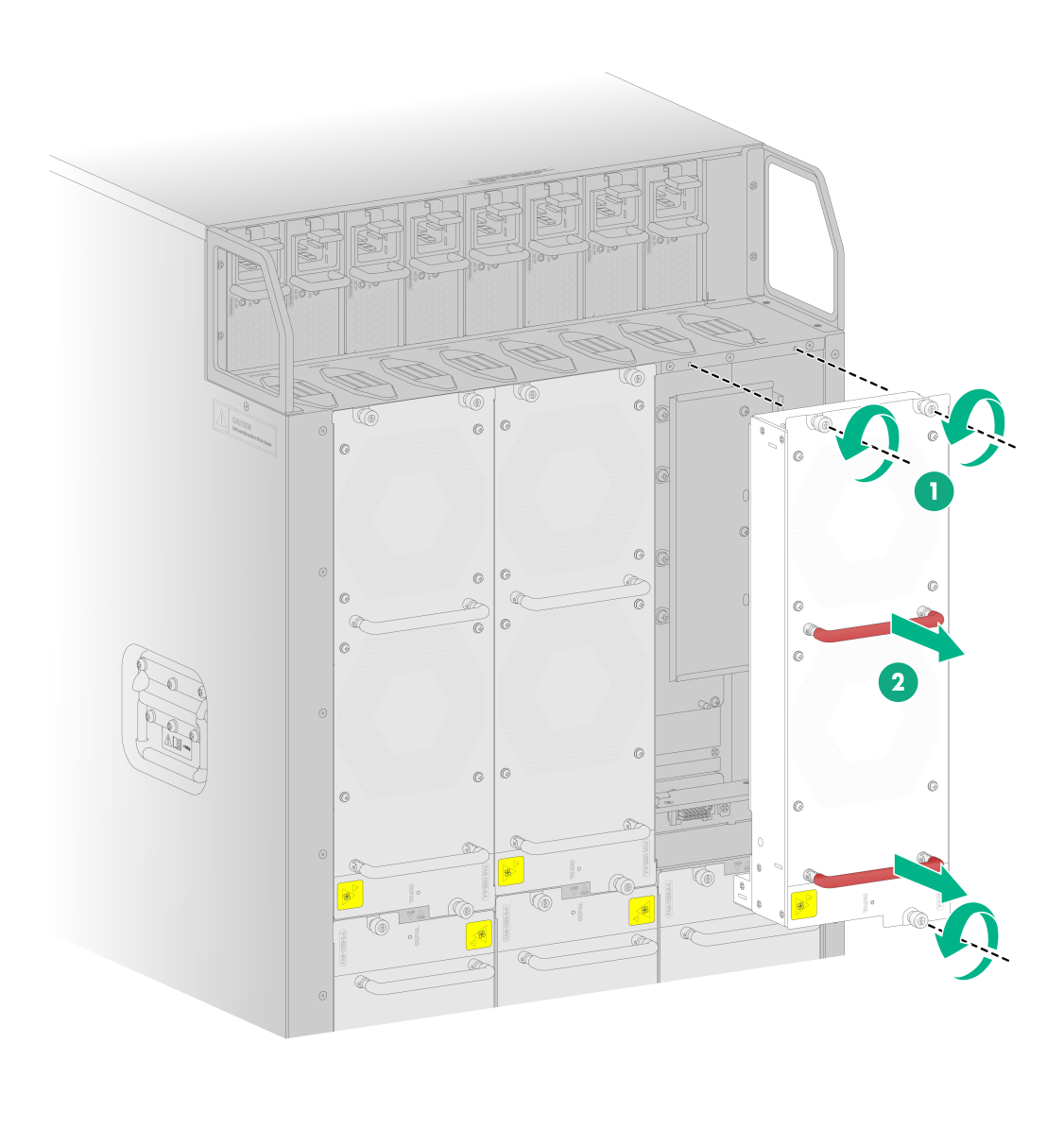
Replacing a switching fabric module for an M9000-AI-E16 gateway
1. Prepare an antistatic mat for placing the removed switching fabric module.
2. Wear an ESD wrist strap, and make sure it makes good skin contact and is reliably grounded.
3. Use a Phillips screwdriver to loosen the captive screws on the module.
4. Open the two ejector levers of the module simultaneously to disengage the module from the backplane. Then pull the module slowly out of the slot.
5. Place the removed module on the antistatic mat.
6. Install a new switching fabric module. For the installation procedure, see "Installing the gateway."
Figure 4 Removing a switching fabric module from an M9000-AI-E16 gateway
Replacing an interface switch module or AI security engine module
The replacement procedure is the same for the interface switch modules and AI security engine modules. This procedure replaces an interface switch module.
1. Prepare an antistatic mat for placing the removed interface switch module.
2. Wear an ESD wrist strap, and make sure it makes good skin contact and is reliably grounded.
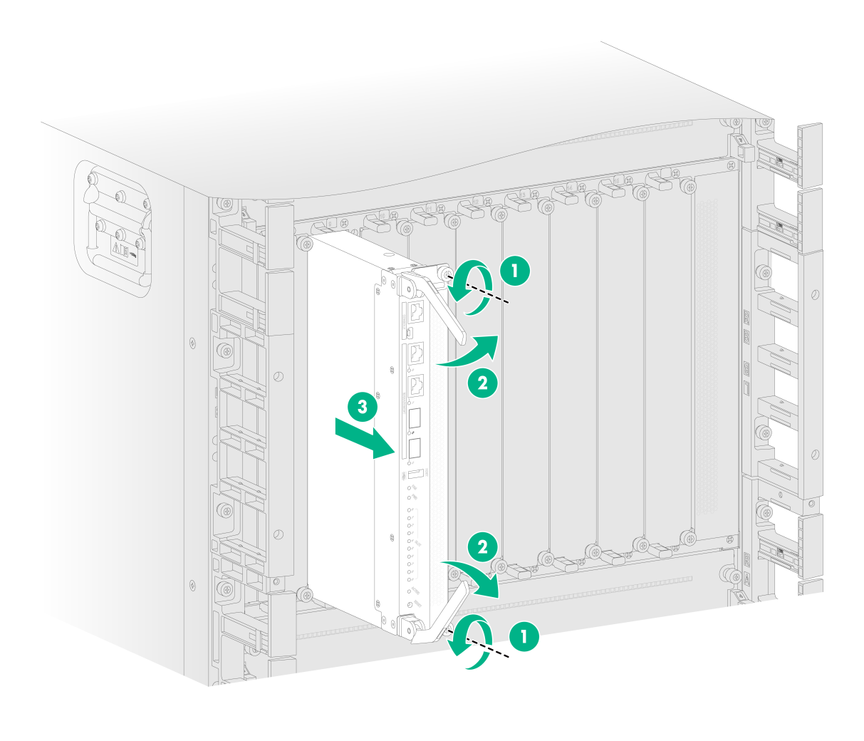
3. Pivot down the ejector levers of the interface switch module.
4. Use a Phillips screwdriver to loosen the captive screws on the module.
5. Open the two ejector levers of the module simultaneously to disengage the module from the backplane. Then pull the module slowly out of the slot.
6. Place the removed module on the antistatic mat.
7. Install a new interface switch module. For the installation procedure, see "Installing the gateway."
Figure 5 Removing an interface switch module (M9000-AI-E16 gateway)
Replacing an interface module or service module
|
|
CAUTION: You cannot hot swap interface modules or service modules on the gateway. |
The replacement procedure is the same for service modules and interface modules. This procedure replaces an interface module.
1. Prepare an antistatic mat for placing the removed interface module.
2. Wear an ESD wrist strap, and make sure it makes good skin contact and is reliably grounded.
3. Remove the interface switch module where the interface module resides. For the removal procedure, see "Replacing an interface switch module or AI security engine module."
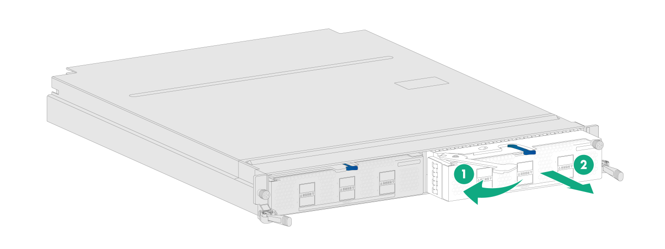
4. Press the release latch to release the ejector lever.
5. Pull the interface module slowly out of the slot.
6. Place the removed interface module on the antistatic mat.
7. Install a new interface module. For the installation procedure, see "Installing the gateway."
Figure 6 Removing an interface module (M9000-AI-E16)
Replacing a transceiver module
|
|
WARNING! · Disconnected optical fibers or transceiver modules might emit invisible laser light. Do not stare into beams or view directly with optical instruments when the gateway is operating. |
|
|
CAUTION: · Make sure the transceiver modules at the two ends of an optical fiber are the same model. · If you are no to install a transceiver module in a fiber port, insert a dust plug into the port. · Do not touch the golden plating on a transceiver module. |
To replace a transceiver module
1. Wear an ESD wrist strap and make sure it makes good skin contact and is reliably grounded.
2. Remove the optical fiber from the transceiver module.
¡ To remove the optical fibers with an LC connector, press the clips on the connector to pull the LC connector out of the port, as shown in Figure 7.
¡ To remove the optical fiber with an MPO connector, hold the front end of the MPO connector to pull the connector out of the port, as shown in Figure 8.
3. Pull down the bail latch on the module to the horizontal position (skip this step for transceiver modules with a plastic bail latch). Hold the bail latch to pull the module horizontally and slowly out of the port.
If the interface module is densely populated with transceiver modules, use tweezers to pull the module out.
4. Insert dust plugs into the transceiver module and put the module into a packaging bag.
5. Install a new transceiver module in the port. For the installation procedure, see "Installing the gateway."
Figure 7 Removing a transceiver module (LC port)
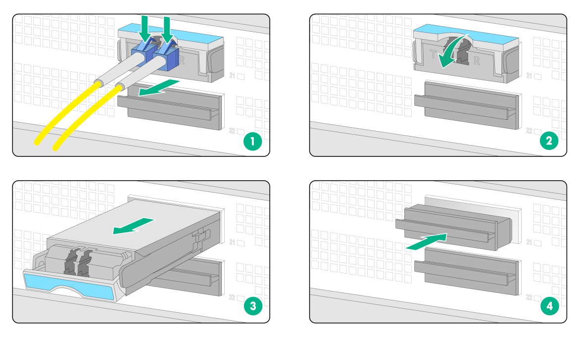
Figure 8 Removing a transceiver module (MPO port)

Replacing a fan tray
|
|
WARNING! · Ensure electricity safety when you hot swap a fan tray. · To avoid bodily injury, do not touch the spinning fans when you replace the fan tray. · When you hot swap a fan tray, the fan rotation speed of the remaining fan trays automatically increases and the fan trays make louder noise. Take protection measures such as wearing an earmuff or earplug. In addition, make good preparations before the hot swapping to minimize the operation time. |
|
|
CAUTION: · When a fan tray fails, replace the faulty fan tray immediately. · To prevent dust from entering the gateway, keep the old fan tray installed in the chassis until a new fan tray is ready to be installed. · Before hot swapping a fan tray, make sure the remaining fan trays can provide sufficient cooling for the router. · If multiple fan trays fail, do not remove the fan trays at the same time. Replace the fan trays one after another and finish replacing each fan tray within 2 minutes to prevent AI security engine modules from overheating and rebooting. |
To replace a fan tray:
1. Prepare an antistatic mat for placing the removed fan tray.
2. Wear an ESD wrist strap. Make sure the wrist strap makes good skin contact and is reliably grounded.
3. Loosen the captive screws on the fan tray.
4. Holding the handles on the fan tray, pull the fan tray part way out of the slot. After the fans stop rotating, pull the fan tray out from the gateway.
5. Place the removed fan tray on the antistatic mat.
6. Install a new fan tray. For the installation procedure, see "Installing the gateway."
Figure 9 Removing a fan tray (M9000-AI-E16 gateway)
Replacing a power supply
|
|
WARNING! · Provide a circuit breaker for each power supply. Before replacing a power supply, turn off the circuit breaker for it. · To reinstall the removed power supply in the chassis, wait until the status LED on it is off. · To avoid being hurt, allow a power supply to cool before removing it. |
Power supply is also called "power module" in this document.
To avoid device damage and bodily injury, strictly follow the procedures shown in Figure 10 and Figure 11 to remove and install a power supply, respectively.
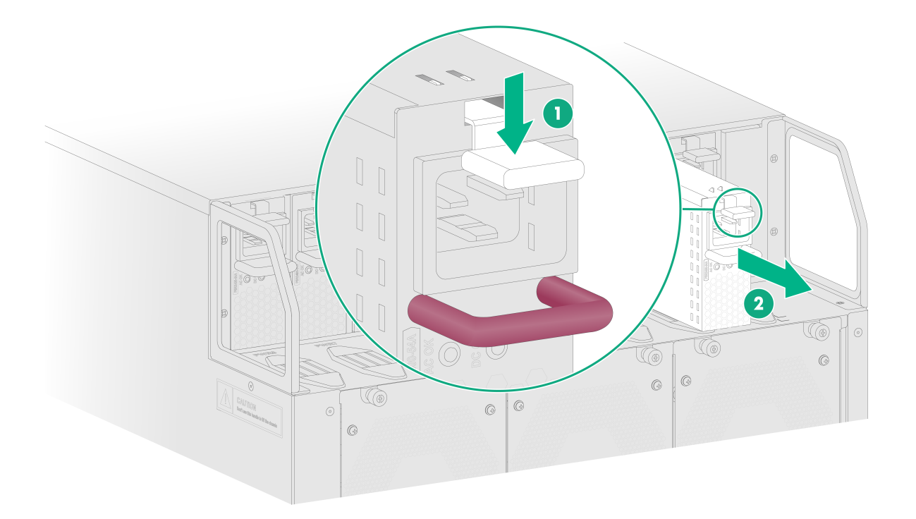
Figure 10 Power supply removal procedure
![]()
Figure 11 Power supply installation procedure
![]()
To replace a power supply:
1. Prepare an antistatic mat to place the removed power supply.
2. Turn off the circuit breaker.
3. Wear an ESD wrist strap, and make sure it makes good skin contact and is reliably grounded.
4. Remove the cable tie, and then remove the power cord connector from the power supply.
5. Press the latch on the power supply towards the handle direction and pull the power supply part way out of the slot.
6. Holding the power supply handle with one hand and supporting the power supply bottom with the other, pull the power supply slowly out of the slot.
7. Place the removed power supply on the antistatic mat.
8. Install a new power supply. For information about the power supply installation procedure, see "Installing the gateway."
Figure 12 Removing a power supply (AC power supply)