- Table of Contents
-
- H3C SecPath M9000-AI-E8[E16] Multi Service Security Gateway Series Installation Guides-6W101
- 00-Preface
- 01-Chapter 1 Chassis views
- 02-Chapter 2 Preparing for Installation
- 03-Chapter 3 Installing the Gateway
- 04-Chapter 4 Accessing the Gateway and Configuring Basic Settings
- 05-Chapter 5 Troubleshooting
- 06-Chapter 6 Replacing Removable Components
- 07-Appendix A FRUs and Compatibility Matrixes
- 08-Appendix B Technical Specifications
- 09-Appendix C LEDs
- 10-Appendix D Cables
- 11-Appendix E Slot arrangement and interface numbering
- 12-Appendix F Engineering labels
- 13-Appendix G Cabling Recommendations
- 14-Appendix H Repackaging the Gateway
- Related Documents
-
| Title | Size | Download |
|---|---|---|
| 04-Chapter 4 Accessing the Gateway and Configuring Basic Settings | 278.56 KB |
Logging in from the Web interface
Logging in from the console port
Setting up the configuration environment
Accessing the gateway
|
|
CAUTION: To ensure device security, change the default login password the first time you log in to the gateway. |
Login methods
The gateway supports the following types of login methods:
· CLI login from the console port—By connecting the console port of the gateway to a configuration terminal, you can log in to the CLI of the gateway. At the CLI, you can configure other access methods.
· Web login—The gateway is provided with factory default Web login information. You can log in to the Web interface of the gateway by using the default Web login information.
· Telnet/SSH login—By using Telnet/SSH, you can access and manage a gateway remotely.
Logging in from the Web interface
The gateway is provided with the default Web login formation. You can use the default Web login information to access the Web interface of the gateway.
The default Web interface login information is as follows:
· Username—admin.
· Password—admin.
· Management Ethernet port and its IP address—The management Ethernet interface is M-GigabitEthernet 0/0/0 and its IP address is 192.168.0.1/24.
To log in to the gateway from the Web interface by using the default Web login formation:
1. Use an Ethernet cable to connect a PC to management Ethernet port M-GigabitEthernet 0/0/0 on the gateway.
2. Assign an IP address (except 192.168.0.1) in subnet 192.168.0.0/24 to the PC. Make sure the PC and the gateway are reachable to each other.
The PC must use a different IP address than M-GigabitEthernet 0/0/0.
3. Start a browser, enter 192.168.0.1 in the address bar, and then press Enter.
4. Enter the default username admin and password admin and then click Login.
5. Modify the login information.
At the first login from the Web interface, change the password as required in the pop-up window, and then click OK.
Keep the new password secure.
Logging in from the console port
Preparation for login
Prepare a console cable and a configuration terminal.
· Console cable:
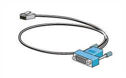
¡ DB9-to-RJ45 console cable—8-core console cable with a crimped RJ-45 connector at one end and a DB-9 female connector at the other end.
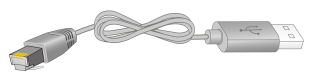
¡ USB-to-RJ45 console cable—8-core console cable with a crimped RJ-45 connector at one end and a standard USB connector at the other end.
· Configuration terminal—Terminal with a serial port such as a PC.
Console cables
As shown in Table 1, two types of console cables can be used for connecting the gateway to a configuration terminal.
Table 1 Connection methods and console cables
|
Connection method |
Console cable type |
Configuration terminal-side connector |
Gateway-side connector |
|
Using the serial console port for connection |
DB9-to-RJ45 console cable |
DB-9 female connector |
RJ-45 connector |
|
USB-to-RJ45 console cable |
USB connector |
RJ-45 connector |
No console cables are provided with the gateway. Prepare them yourself as required.
The RJ-45 signal pinout varies by the vendor of the cable. To avoid abnormal display on the configuration terminal, use a console cable provided by H3C (as shown in Table 2). To prepare a console cable yourself, make sure the RJ-45 connector signal pinout is the same as that of a serial console cable provided by H3C.
For more information about the console cable signal pinout, see "Appendix D Cables."
|
Console cable type |
Console cable view |
Product code for the recommended H3C console cable |
|
DB9-to-RJ45 console cable |
|
04042967 |
|
USB-to-RJ45 console cable |
|
0404A1EE |
Setting up the configuration environment
Connecting a DB9-to-RJ45 console cable
1. Prepare a console cable and a configuration terminal.
¡ Console cable—8-core console cable with a crimped RJ-45 connector at one end and a DB-9 female connector at the other end.
¡ Configuration terminal—Terminal with a serial port such as a PC.
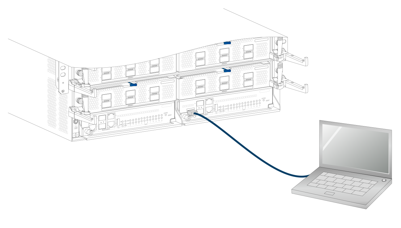
2. Plug the DB-9 female connector of the console cable to the RS-232 port on the PC.
3. Plug the RJ-45 connector of the console cable to the console port on the gateway.
|
|
NOTE: The serial ports on PCs do not support hot swapping. To connect a PC to an operating gateway, first connect the PC end. To disconnect a PC from an operating gateway, first disconnect the gateway end. |
Figure 1 Setting up the configuration environment (M9000-AI-E8)
Connecting a USB-to-RJ45 console cable
|
|
IMPORTANT: · To use a USB-to-RJ45 console cable to connect the gateway to a configuration terminal, first download and install the USB-to-RJ45 console driver on the configuration terminal, and then connect the USB-to-RJ45 console cable to the configuration terminal. To download the USB-to-RJ45 console driver, access the H3C official website or scan the QR code on the cable package. · If you have connected a USB-to-RJ45 console cable to the configuration terminal before driver installation, you must remove and reconnect the USB-to-RJ45 console cable to the configuration terminal. |
The following installs the driver on the Windows system. To install the driver on other operating systems, see the installation guide in the driver compression package named by the corresponding operating system.
To connect the gateway to the configuration terminal through a USB-to-RJ45 console cable:
1. Click the following link, or copy it to the address bar on your browser and download the USB-to-RJ45 console driver.
http://www.h3c.com/en/home/USB_to_RJ45_Console/
2. View the TXT file Read me in the Windows folder to check whether the Windows system of the configuration terminal supports the driver.
3. If the Windows system supports the driver, install PL23XX-M_LogoDriver_Setup_v200_20190815.exe.
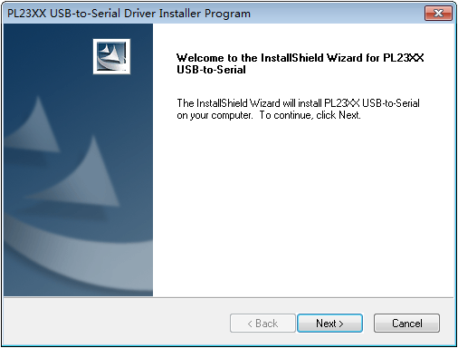
4. Click Next on the welcome page of the driver installation wizard.
Figure 2 Driver installation wizard
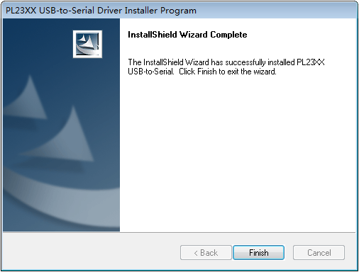
5. Click Finish after the driver installation is completed.
Figure 3 Finishing the driver installation
6. Connect the standard USB connector of the cable to the USB port of the configuration terminal.
7. Connect the RJ-45 connector of the cable to the console port of the gateway.
Setting terminal parameters
The first time you log in to the gateway, you can log in to the CLI of the gateway from the console port. The default console port login information is as follows:
· Authentication method—scheme
· Username—admin
· Password—admin
To configure and manage the gateway through the console port, you must run a terminal emulator program, TeraTermPro or PuTTY, on your configuration terminal. You can use the emulator program to connect a network device, a Telnet site, or an SSH site. For more information about the terminal emulator programs, see the user guides for these programs.
Start the terminal emulator program and configure the parameters as follows:
· Bits per second—9600.
· Data bits—8.
· Stop bits—1.
· Parity—None.
· Flow control—None.
Verifying the configuration
1. Power on the gateway.
2. Verify the following items:
¡ The cooling system is working, and you can hear fan rotating noise and feel air being blown out.
¡ The LEDs on the supervisor engine module indicate that the system is operating correctly. For more information about the LED status, see "Appendix C LEDs."
¡ The console terminal displays information correctly. You can see the startup window on the console terminal. After the POST, the system prompts you to press Enter. If you can log in to the CLI of the gateway, the configuration is correct.
Logging in through Telnet
1. Log in to the gateway from the console port.
2. Execute the telnet server enable command in system view to enable the Telnet function.
3. Enter VTY user line view, and configure the authentication mode, user role, and common properties.
By default, the authentication mode is scheme, the username is admin, and the password is admin.
4. Use an Ethernet cable to connect a PC to the management Ethernet port on the supervisor engine module of the gateway.
5. Specify an IP address for the PC. Make sure the PC and the gateway are reachable to each other.
By default, the IP address of the management Ethernet interface on the gateway is 192.168.0.1/24.
6. Run the Telnet client on the PC and enter the login information.
The default login username and password are both admin.
Configuring basic settings
After logging in to the gateway, you can configure basic settings for the gateway. For more information, see the configuration guides and command references for the gateway.
