- Table of Contents
-
- H3C SecPath M9000-AI-E8[E16] Multi Service Security Gateway Series Installation Guides-6W101
- 00-Preface
- 01-Chapter 1 Chassis views
- 02-Chapter 2 Preparing for Installation
- 03-Chapter 3 Installing the Gateway
- 04-Chapter 4 Accessing the Gateway and Configuring Basic Settings
- 05-Chapter 5 Troubleshooting
- 06-Chapter 6 Replacing Removable Components
- 07-Appendix A FRUs and Compatibility Matrixes
- 08-Appendix B Technical Specifications
- 09-Appendix C LEDs
- 10-Appendix D Cables
- 11-Appendix E Slot arrangement and interface numbering
- 12-Appendix F Engineering labels
- 13-Appendix G Cabling Recommendations
- 14-Appendix H Repackaging the Gateway
- Related Documents
-
| Title | Size | Download |
|---|---|---|
| 11-Appendix E Slot arrangement and interface numbering | 286.47 KB |
Appendix E Slot arrangement and interface numbering
Card slot arrangement
Figure 1 Card slot arrangement for the M9000-AI-E8
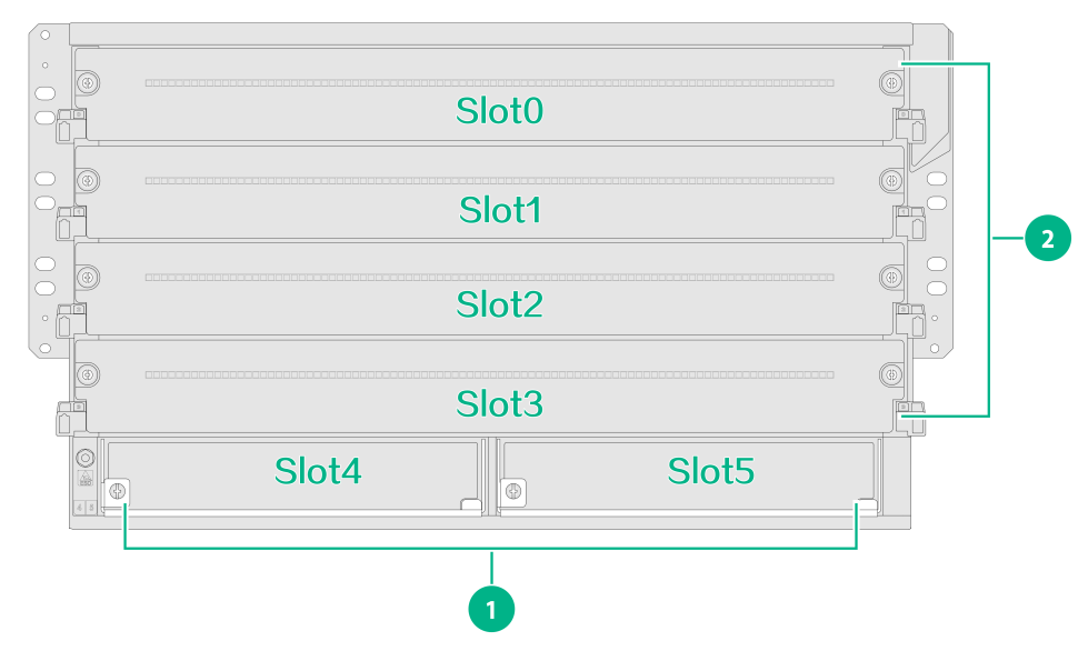
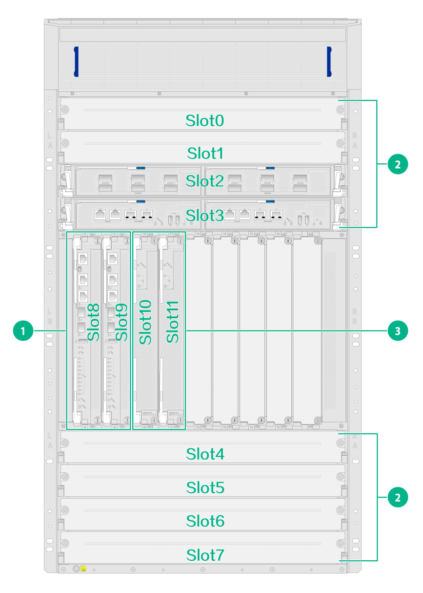
Figure 2 Card slot arrangement for the M9000-AI-E16
From left to right, Figure 1 shows the slot arrangement on the gateways.
|
Model |
Card slot arrangement |
Slot mark location |
|
M9000-AI-E8 |
Supervisor engine module (SEM) slots: slots 4 and 5 |
At the left edge of the slot |
|
Slots for interface switch modules and service modules: slots 0 through 3 |
At the left and right edges of the slot |
|
|
M9000-AI-E16 |
SEM slots: slots 8 and 9 |
At the right edge of the slot |
|
Slots for interface switch modules and service modules: slots 0 through 7 Slots 10 through 15 |
At the top and bottom edges of the slot |
|
|
NOTE: To install an interface module or service module on the gateway, first install it on an interface switch module and then install the interface switch module on the gateway. For the interface module slots and service module slots, see the card manuals that come with the interface modules and service modules. |
Example
You can execute the display device command to view the slot arrangement on the device.
<Sysname> display device
Slot NO Brd Type Brd Status Subslot Sft Ver Patch
1 NSQM5MBSHA1 Normal 0 M9000-AI-E8-9001P06 None
Interface numbering
The gateway provides many types of interfaces, including console, M-GigabitEthernet, Ten-GigabitEthernet, Forty-GigabitEthernet, Hundred-GigabitEthernet, blade, aggregate, tunnel, Virtual-Template, and VLAN interfaces.
The numbering of the gateway interfaces varies by the gateway mode.
· Standalone mode—interface-type X/Y/Z.
· IRF mode—interface-type W/X/Y/Z.
Where,
· interface-type—Type of the interface such as GigabitEthernet interface.
· W—IRF member device ID.
· X—Number of the slot where the card resides. For more information about the slot number on the gateway, see Table 1.
· Y—Number of the slot where the subcard resides on the interface switch module. The value is 1 or 2.
· Z—Number of the port on the card. The number starts from 1 for each port type.
The management ports are numbered M-GE0/0/0, M-GE0/0/1, M-GE0/0/2, and M-GE0/0/3, respectively when the gateway operates in standalone mode and M-GE1/0/0/0, M-GE1/0/0/1, M-GE1/0/0/2, and M-GE1/0/0/3, respectively when the gateway operates in IRF mode.
Example
· The gateway operates in standalone mode and has an interface switch module installed in slot 2 and an NS-C300-TG24A1 interface module installed in slot 1 of the interface switch module. The interfaces on the interface module are numbered as shown in the output of the display interface Ten-GigabitEthernet brief command.
<Sysname> display interface Ten-GigabitEthernet brief
Brief information on interface(s) in route mode:
Link: ADM - administratively down; Stby - standby
Protocol: (s) - spoofing
Interface Link Protocol Primary IP Description
XGE2/1/1 DOWN DOWN --
XGE2/1/2 DOWN DOWN --
XGE2/1/3 DOWN DOWN --
XGE2/1/4 DOWN DOWN --
……
XGE2/1/23 DOWN DOWN --
XGE2/1/24 DOWN DOWN --
· The gateway operates in IRF mode and its IRF member device ID is 1. An interface switch module is installed in slot 2 of the gateway and an NS-C300-TG24A1 interface module in slot 1 of the interface switch module. The interfaces on the interface module are numbered as shown in the output of the display interface Ten-GigabitEthernet brief command.
<Sysname> display interface Ten-GigabitEthernet brief
Brief information on interface(s) in route mode:
Link: ADM - administratively down; Stby - standby
Protocol: (s) - spoofing
Interface Link Protocol Primary IP Description
XGE1/2/1/1 DOWN DOWN --
XGE1/2/1/2 DOWN DOWN --
XGE1/2/1/3 DOWN DOWN --
XGE1/2/1/4 DOWN DOWN --
XGE1/2/1/5 DOWN DOWN --
……
XGE1/2/1/23 DOWN DOWN --
XGE1/2/1/24 DOWN DOWN --
