- Table of Contents
-
- H3C SecPath M9000-AI-E8[E16] Multi Service Security Gateway Series Installation Guides-6W101
- 00-Preface
- 01-Chapter 1 Chassis views
- 02-Chapter 2 Preparing for Installation
- 03-Chapter 3 Installing the Gateway
- 04-Chapter 4 Accessing the Gateway and Configuring Basic Settings
- 05-Chapter 5 Troubleshooting
- 06-Chapter 6 Replacing Removable Components
- 07-Appendix A FRUs and Compatibility Matrixes
- 08-Appendix B Technical Specifications
- 09-Appendix C LEDs
- 10-Appendix D Cables
- 11-Appendix E Slot arrangement and interface numbering
- 12-Appendix F Engineering labels
- 13-Appendix G Cabling Recommendations
- 14-Appendix H Repackaging the Gateway
- Related Documents
-
| Title | Size | Download |
|---|---|---|
| 02-Chapter 2 Preparing for Installation | 542.73 KB |
Preparing for installation
H3C SecPath M9000-AI multiservice security gateways include the M9000-AI-E8 gateway and M9000-AI-E16 gateway.
Safety recommendations
To avoid bodily injury and equipment damage, read all safety recommendations carefully before installation. Note that the recommendations do not cover every possible hazardous condition.
General safety recommendations
· Keep the gateway clean and dust-free.
· Do not place the gateway on a moist area, and avoid liquid flowing into the gateway.
· Make sure the ground is dry and flat and anti-slip measures are in place.
· Keep the gateway and installation tools away from walk areas.
· Do not wear loose clothing, jewelry (for example, necklace) or any other things that could get caught in the gateway when you install and maintain the gateway.
Electricity safety
· Clear the work area of possible electricity hazards, such as ungrounded power extension cables, missing safety grounds, and wet floors.
· Locate the emergency power-off switch in the room before installation so you can quickly shut power off when an electrical accident occurs.
· Unplug all external cables, including power cords, before moving the gateway.
· Do not work alone when the gateway has power.
· Always verify that power has been disconnected from a circuit.
Handling safety
When you move the gateway, follow these guidelines:
· Remove all external cables, including the power cords, before moving the gateway.
· As a best practice, use a mechanical lift to move the gateway. To move the gateway manually, use multiple people.
· Lift and put down the gateway slowly and never move suddenly.
· Hold the handles of the gateway.
ESD prevention
To prevent the electric component from being damaged by electrostatic discharge (ESD), follow these guidelines:
· Ground the gateway correctly.
· Always wear an ESD wrist strap and make sure it is correctly grounded when installing FRUs.
· Hold a PCB by its edges. Do not touch any electronic components or printed circuit.
· Put modules away in antistatic bags for future use.
|
|
NOTE: The gateway has an ESD socket at both the front and rear. |
Laser safety
|
|
WARNING! · Disconnected optical fibers or transceiver modules might emit invisible laser light. Do not stare into beams or view directly with optical instruments when the gateway is operating. · Before you remove the optical fiber connector from a fiber port, execute the shutdown command in interface view to shut down the port. |
|
|
CAUTION: · Insert optical fiber caps into open optical fiber connectors to protect them from contamination and ESD damage. · Insert dust plugs into open fiber ports and transceiver module ports to protect them from contamination and ESD damage. |
Examining the installation site
The gateway must be used indoors. To ensure the correct operation and long service life of your gateway, the installation site must meet the requirements in this section.
Weight support
Make sure the floor can support the total weight of the rack, gateway, and accessories. Additionally, the floor loading plan must also consider system expansion, such as adding more modules. For more information, see "Appendix B Technical Specifications."
Space
For easy installation and maintenance, make sure the following requirements are met:
· Make sure the rack has enough space (in height and depth) to accommodate the gateway.
· The rack allows front and rear access to the gateway.
· A minimum clearance of 1.2 m (3.94 ft) is reserved between the rack and walls or other devices.
For more information about the gateway dimensions, see "Appendix B Technical Specifications."
Table 1 Gateway dimensions and rack requirements
|
Model |
Gateway dimensions |
Rack requirements |
|
M9000-AI-E8 |
· Height—264 mm (10.39 in) · Width—440 mm (17.32 in) · Depth—977 mm (38.46 in) ¡ 857 mm (33.74 in) for the gateway ¡ 90 mm (3.54 in) for the cable management brackets at the gateway front ¡ 30 mm (1.18 in) for the ejector levers of the fan tray at the gateway rear |
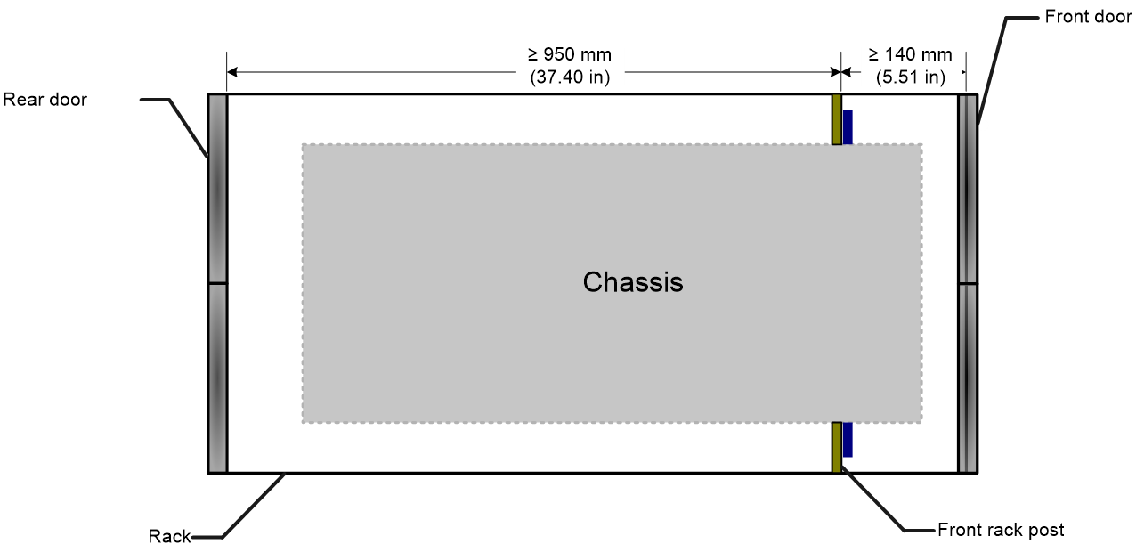
· A minimum of 1.1 m (3.61 ft) in depth (recommended). · A minimum of 140 mm (5.51 in) between the front rack posts and the front door. · A minimum of 950 mm (37.40 in) between the front rack posts and the rear door. |
|
M9000-AI-E16 |
· Height—841.7 mm (33.14 in) · Width—440 mm (17.32 in) · Depth—735 mm (28.94 in) ¡ 640 mm (25.20 in) for the gateway ¡ 95 mm (3.74 in) for the cable management brackets at the gateway front ¡ 12 mm (0.47 in) for the captive screw of the fan tray at the gateway rear |
Figure 1 Rack dimensions
Cooling
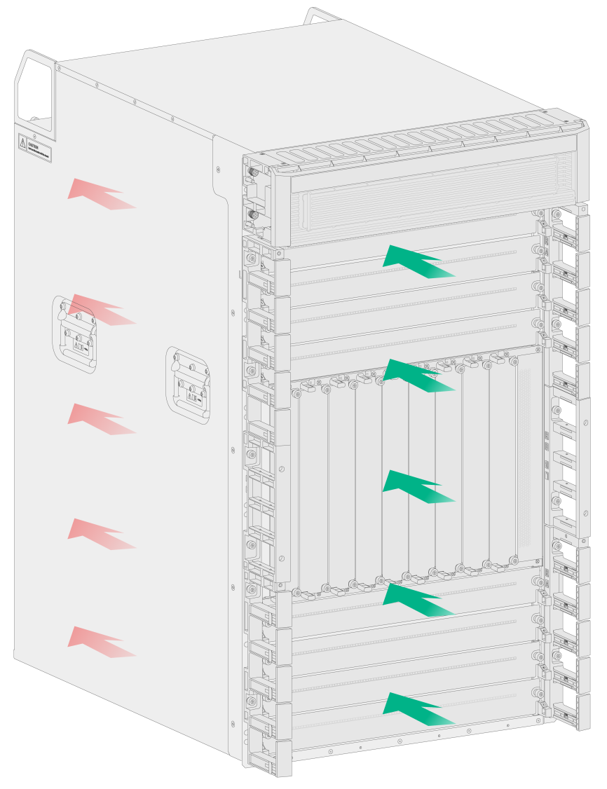
The gateway uses front-to-rear airflow for heat dissipation. Plan the installation site for the gateway based on its airflow direction for adequate ventilation. Make sure the following requirements are met:
· The installation site has a good cooling system.
· The rack for the gateway has a good cooling system.
· Leave a minimum clearance of 300 mm (11.81 in) around the inlet and outlet air vents.
Figure 2 Airflow through the gateway (M9000-AI-E16 gateway)
Power
A good power supply system is essential for correct operation of the gateway. The gateway supports AC, DC, and high-voltage DC power inputs. Make sure the equipment room meets the following requirements for the power supply systems.
· The AC power supply system is stable and reliable and capable of providing power required by the gateway. Prepare a diesel generator as a backup power source except for the power lines.
· The DC power supply system is stable and reliable and its output voltage is stable and within the acceptable range allowed by the gateway.
· Enough batteries are available to ensure uninterrupted device operation in the event of a power failure.
For the power supply system to provide power as required by the router:
1. Calculate the system power consumption.
The system power consumption varies by module type and density. For more information about system power consumption calculation, see "Appendix B Technical Specifications."
2. Select power supplies and identify the number of power supplies.
The total maximum output power of all power supplies must be higher than the system power consumption. For more information about available power supplies, see "Appendix A FRUs and Compatibility Matrixes."
Lightning protection
To protect the gateway from the lightning, make sure the following requirements are met:
· The grounding cable for the gateway is correctly grounded.
· The grounding terminal of the AC power receptacle is correctly grounded.
· If an AC power cord is routed from outdoors for connecting to the device, connect the power cord first to a power lightning arrester before connecting it to the power receptacle on the device.
· If a network cable is routed from outdoors for connecting to the device, connect the network cable first to a network port lightning arrester before connecting it to the port.
|
|
IMPORTANT: · No network port lightning arrester or AC power lightning arrester is provided with the device. Purchase them as required. · For the technical specifications and installation instructions for the lightning arresters, see the documents shipped with them. |
Temperature
|
CAUTION: If condensation appears on the gateway when you move it to a high-temperature environment, dry the gateway before powering it on to avoid short circuits. |
If the temperature in the equipment room is too high, too low, or changes dramatically, the device reliability is reduced and its service lifetime is shortened.
High temperature can accelerate the aging of insulation materials and significantly lower the reliability and lifespan of the gateway.
To ensure the correct operation of the gateway, make sure the room temperature meets the requirements in Table 2.
Table 2 Temperature requirements
|
Temperature |
Range |
|
Operating temperature |
0°C to 45°C (32°F to 113°F) |
|
Storage temperature |
–40°C to +70°C (–40°F to +158°F) |
Humidity
Maintain appropriate humidity in your equipment room, as described in Table 3.
· Lasting high relative humidity tends to cause poor insulation, electricity leakage, mechanical property change of materials, and corrosion of metal parts.
· Lasting low relative humidity is likely to result in loose screws due to washer contraction, and even electrostatic discharge (ESD), which causes the circuits to fail.
|
Humidity |
Range |
|
Operating humidity |
5% RH to 95% RH, noncondensing |
|
Storage humidity |
5% RH to 95% RH, noncondensing |
Cleanliness
Dust buildup on the gateway might result in electrostatic adsorption, which causes poor contact of metal components and contact points. In the worst case, electrostatic adsorption can cause communication failure.
Table 4 Dust concentration limit in the equipment room
|
Substance |
Concentration limit (particles/m3) |
|
Dust particles |
≤ 3 x 10⁴ (No visible dust on desk in three days) |
|
NOTE: Dust particle diameter ≥ 5 µm |
|
The equipment room must also meet limits on salts, acids, and sulfides to eliminate corrosion and premature aging of components, as shown in Table 5.
Table 5 Harmful gas limits in an equipment room
|
Gas |
Max. (mg/m3) |
|
SO2 |
1.0 |
|
H2S |
0.5 |
|
NH3 |
3.0 |
|
Cl2 |
0.3 |
|
NO2 |
1.0 |
EMI
Electromagnetic interference (EMI) might be coupled from the source to the gateway through the following coupling mechanisms:
· Capacitive coupling
· Inductive coupling
· Radiative coupling
· Common impedance coupling
· Conductive coupling
To prevent EMI, take the following actions:
· Filter interference from the power grid.
· Keep the gateway grounding facilities away from grounding and lightning protection facilities of other devices.
· Keep the gateway far away from radio transmitting stations, radar stations, and high-frequency devices to make sure the EMI levels do not exceed the compliant range.
· Use electromagnetic shielding, for example, shielded interface cables, when necessary.
Installation tools and accessories
No installation tools are provided with the gateway. Prepare them yourself as required.
Figure 3 Installation tools
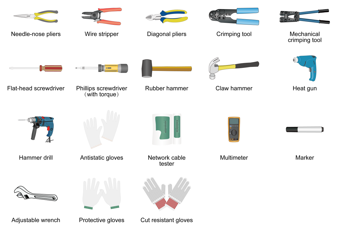
Figure 4 Installation accessories

Pre-installation checklist
Table 6 Pre-installation checklist
|
Item |
Requirements |
Result |
|
|
Installation site |
Load bearing |
· The floor or ground at the installation site can support the sum of the weight of the gateway and the rack. · The slide rails can support the weight of the gateway. |
|
|
Space |
· There is a minimum clear height of 3 m (9.84 ft) (from the beam or the air duct to the floor) in the equipment room. · There is a minimum clearance of 1200 mm (47.24 in) between the rack and walls or other devices. |
|
|
|
Ventilation |
· There is a minimum clearance of 300 mm (11.81 in) around the inlet and outlet air vents. · A good ventilation system is available at the installation site. |
|
|
|
Power supply |
· The power supply system can output enough power to maintain the device operation. · An uninterrupted power supply (UPS) is available. · The power-off switch in the equipment room is located so that the power can be immediately shut off when an accident occurs. |
|
|
|
Grounding |
· The grounding specifications for the equipment room comply with national and industry standards. · All communication devices in the equipment room are reliably grounded. · The working earthing and protective earthing systems of the communication power supplies use the same earthing conductor set with the protective earthing system of the communication devices. |
|
|
|
Temperature |
0°C to 45°C (32°F to 113°F). |
|
|
|
Humidity |
5% RH to 95% RH (noncondensing). |
|
|
|
Cleanliness |
· Dust concentration ≤ 3 × 10⁴ particles/m3. · No visible dust on desk within three days. |
|
|
|
EMI prevention |
· Take effective measures to protect the power system from the power grid system. · Separate the operation ground of the gateway from the grounding device or lightning protection grounding device as far as possible. · Keep the gateway far away from radio stations, radar and high-frequency devices working in high current. · Use electromagnetic shielding when necessary. |
|
|
|
Safety precautions |
· The gateway is far away from any heat source and moist area. · The emergency power switch in the equipment room is located. |
|
|
|
Accessories |
Installation accessories provided with the gateway. |
|
|
|
Reference |
· Documents shipped with the gateway. · Online documents. |
|
|
