- Table of Contents
-
- 02-Typical configuration example
- 01-AAA_Configuration_Examples
- 02-ACL_Configuration_Examples
- 03-ATM_Configuration_Examples
- 04-IGMP_Configuration_Examples
- 05-IP_Source_Guard_Configuration_Examples
- 06-Ethernet_OAM_Configuration_Examples
- 07-NQA_Configuration_Examples
- 08-QinQ_Configuration_Examples
- 09-OSPF_Configuration_Examples
- 10-MPLS_TE_Configuration_Examples
- 11-OpenFlow_Configuration_Examples
- 12-NAT_Configuration_Examples
- 13-RBAC_Configuration_Examples
- 14-IRF_Configuration_Examples
- 15-POS_Interface_Configuration_Examples
- 16-CPOS_Interface_Configuration_Examples
- 17-DLDP_Configuration_Examples
- 18-IS-IS_Configuration_Examples
- 19-MPLS_L3VPN_Configuration_Examples
- 20-SSH_Configuration_Examples
- 21-Login_Management_Configuration_Examples
- 22-SNMP_Configuration_Examples
- 23-Priority_Marking_and_Queue_Scheduling_Configuration_Examples
- 24-Multicast_VPN_Configuration_Examples
- 25-BGP_Configuration_Examples
- 26-HoVPN_Configuration_Examples
- 27-L2TP_Configuration_Examples
- 28-VRRP_Configuration_Examples
- 29-Traffic_Filtering_Configuration_Examples
- 30-Samplers_and_IPv4_NetStream_Configuration_Examples
- 31-Software_Upgrade_Examples
- 32-MPLS_L2VPN_Configuration_Examples
- 33-NetStream_Configuration_Examples
- 34-Policy-Based_Routing_Configuration_Examples
- 35-Traffic_Policing_Configuration_Examples
- 36-BFD_Configuration_Examples
- 37-OSPFv3_Configuration_Examples
- 38-VPLS_Configuration_Examples
- 39-GTS_and_Rate_Limiting_Configuration_Examples
- 40-IPv6_IS-IS_Configuration_Examples
- 41-MPLS OAM_Configuration_Examples
- 42-BGP_Route_Selection_Configuration_Examples
- 43-IS-IS_Route_Summarization_Configuration_Examples
- 44-Attack_Protection_Configuration_Examples
- Related Documents
-
| Title | Size | Download |
|---|---|---|
| 41-MPLS OAM_Configuration_Examples | 144.20 KB |
Introduction
This document provides MPLS OAM configuration examples.
MPLS Operation, Administration, and Maintenance (OAM) provides fault management tools for the following purposes:
· MPLS data plane connectivity verification.
· Data plane and control plane consistency verification.
· Fault isolation.
Prerequisites
The configuration examples in this document were created and verified in a lab environment, and all the devices were started with the factory default configuration. When you are working on a live network, make sure you understand the potential impact of every command on your network.
This document assumes that you have basic knowledge of MPLS OAM.
Example: Configuring BFD for an LSP
Network configuration
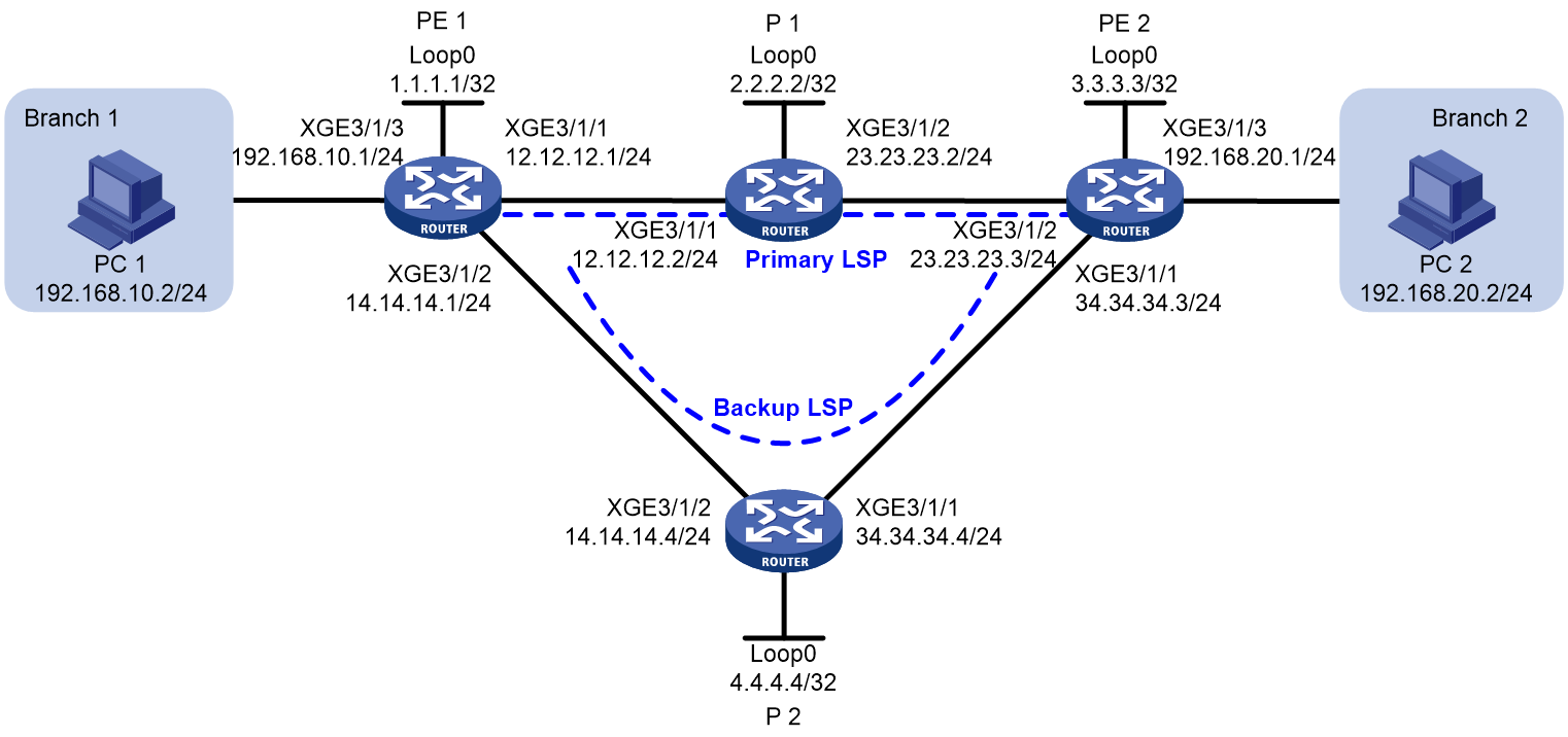
As shown in Figure 1, Branch 1 and Branch 2 of a company are connected to each other through an MPLS backbone of the ISP. The branches need to exchange real-time data.
To ensure high availability of the real-time service between the branches, deploy LDP FRR on the MPLS backbone to provide a primary LSP and a backup LSP. Configure BFD for the primary LSP, so when the primary LSP fails, BFD can quickly detect the failure and notify LDP of the failure to trigger a traffic switchover to the backup LSP.
Procedures
1. Assign IP addresses to interfaces:
# Assign an IP address to Ten-GigabitEthernet 3/1/1 on PE 1.
<PE1> system-view
[PE1] interface ten-gigabitethernet 3/1/1
[PE1-Ten-GigabitEthernet3/1/1] ip address 12.12.12.1 24
[PE1-Ten-GigabitEthernet3/1/1] quit
# Assign IP addresses to other interfaces (including the loopback interfaces) according to Figure 1. (Details not shown.)
2. On the MPLS backbone, configure OSPF to ensure IP connectivity between the routers, and enable OSPF FRR.
# Configure PE 1.
[PE1] ospf
[PE1-ospf-1] area 0
[PE1-ospf-1-area-0.0.0.0] network 1.1.1.1 0.0.0.0
[PE1-ospf-1-area-0.0.0.0] network 12.12.12.0 0.0.0.255
[PE1-ospf-1-area-0.0.0.0] network 14.14.14.0 0.0.0.255
[PE1-ospf-1-area-0.0.0.0] network 192.168.10.0 0.0.0.255
[PE1-ospf-1-area-0.0.0.0] quit
[PE1-ospf-1] fast-reroute lfa
[PE1-ospf-1] quit
# Configure P.
[P1] ospf
[P1-ospf-1] area 0
[P1-ospf-1-area-0.0.0.0] network 2.2.2.2 0.0.0.0
[P1-ospf-1-area-0.0.0.0] network 12.12.12.0 0.0.0.255
[P1-ospf-1-area-0.0.0.0] network 23.23.23.0 0.0.0.255
[P1-ospf-1-area-0.0.0.0] quit
[P1-ospf-1] quit
# Configure PE 2.
[PE2] ospf
[PE2-ospf-1] area 0
[PE2-ospf-1-area-0.0.0.0] network 3.3.3.3 0.0.0.0
[PE2-ospf-1-area-0.0.0.0] network 23.23.23.0 0.0.0.255
[PE2-ospf-1-area-0.0.0.0] network 34.34.34..0 0.0.0.255
[PE2-ospf-1-area-0.0.0.0] network 192.168.20.0 0.0.0.255
[PE2-ospf-1-area-0.0.0.0] quit
[PE2-ospf-1] fast-reroute lfa
[PE2-ospf-1] quit
# Configure P 2.
[P2] ospf
[P2-ospf-1] area 0
[P2-ospf-1-area-0.0.0.0] network 4.4.4.4 0.0.0.0
[P2-ospf-1-area-0.0.0.0] network 14.14.14.0 0.0.0.255
[P2-ospf-1-area-0.0.0.0] network 34.34.34.0 0.0.0.255
[P2-ospf-1-area-0.0.0.0] quit
[P2-ospf-1] quit
# Adjust the OSPF cost values of Ten-GigabitEthernet 3/1/1 and Ten-GigabitEthernet 3/1/2 to ensure that the OSPF cost of the backup LSP is greater than that of the primary LSP.
[P2] interface ten-gigabitethernet 3/1/1
[P2-Ten-GigabitEthernet3/1/1] ospf cost 10
[P2-Ten-GigabitEthernet3/1/1] quit
[P2] interface ten-gigabitethernet 3/1/2
[P2-Ten-GigabitEthernet3/1/2] ospf cost 10
[P2-Ten-GigabitEthernet3/1/2] quit
3. Configure basic MPLS and enable LDP.
# Configure PE 1.
[PE1] mpls lsr-id 1.1.1.1
[PE1] mpls ldp
[PE1-ldp] quit
[PE1] interface ten-gigabitethernet 3/1/1
[PE1-Ten-GigabitEthernet3/1/1] mpls enable
[PE1-Ten-GigabitEthernet3/1/1] mpls ldp enable
[PE1-Ten-GigabitEthernet3/1/1] quit
[PE1] interface ten-gigabitethernet 3/1/2
[PE1-Ten-GigabitEthernet3/1/2] mpls enable
[PE1-Ten-GigabitEthernet3/1/2] mpls ldp enable
[PE1-Ten-GigabitEthernet3/1/2] quit
# Configure P 1.
[P1] mpls lsr-id 2.2.2.2
[P1] mpls ldp
[P1-ldp] quit
[P1] interface ten-gigabitethernet 3/1/1
[P1-Ten-GigabitEthernet3/1/1] mpls enable
[P1-Ten-GigabitEthernet3/1/1] mpls ldp enable
[P1-Ten-GigabitEthernet3/1/1] quit
[P1] interface ten-gigabitethernet 3/1/2
[P1-Ten-GigabitEthernet3/1/2] mpls enable
[P1-Ten-GigabitEthernet3/1/2] mpls ldp enable
[P1-Ten-GigabitEthernet3/1/2] quit
# Configure PE 2.
[PE2] mpls lsr-id 3.3.3.3
[PE2] mpls ldp
[PE2-ldp] quit
[PE2] interface ten-gigabitethernet 2/0/1
[PE2-Ten-GigabitEthernet2/0/1] mpls enable
[PE2-Ten-GigabitEthernet2/0/1] mpls ldp enable
[PE2-Ten-GigabitEthernet2/0/1] quit
[PE2] interface ten-gigabitethernet 2/0/2
[PE2-Ten-GigabitEthernet2/0/2] mpls enable
[PE2-Ten-GigabitEthernet2/0/2] mpls ldp enable
[PE2-Ten-GigabitEthernet2/0/2] quit
# Configure P 2.
[P2] mpls lsr-id 4.4.4.4
[P2] mpls ldp
[P2-ldp] quit
[P2] interface ten-gigabitethernet 3/1/1
[P2-Ten-GigabitEthernet3/1/1] mpls enable
[P2-Ten-GigabitEthernet3/1/1] mpls ldp enable
[P2-Ten-GigabitEthernet3/1/1] quit
[P2] interface ten-gigabitethernet 3/1/2
[P2-Ten-GigabitEthernet3/1/2] mpls enable
[P2-Ten-GigabitEthernet3/1/2] mpls ldp enable
[P2-Ten-GigabitEthernet3/1/2] quit
After the previous configuration, you can see that the state of LDP sessions is Operational. Take PE 1 as an example:
[PE1] display mpls ldp peer
Total number of peers: 2
Peer LDP ID State Role GR MD5 KA Sent/Rcvd
2.2.2.2:0 Operational Passive Off Off 55/55
4.4.4.4:0 Operational Passive Off Off 6/6
# On PE 1, create an IP prefix list named PE1. Configure that only the routes permitted by the prefix can trigger LDP to establish LSPs.
[PE1] ip prefix-list PE1 index 10 permit 192.168.10.0 24
[PE1] ip prefix-list PE1 index 20 permit 192.168.20.0 24
[PE1] ip prefix-list PE1 index 30 permit 1.1.1.1 32
[PE1] ip prefix-list PE1 index 40 permit 3.3.3.3 32
[PE1] mpls ldp
[PE1-ldp] lsp-trigger prefix-list PE1
[PE1-ldp] quit
# On P 1, create an IP prefix list named P1. Configure that only the routes permitted by the prefix can trigger LDP to establish LSPs.
[P1] ip prefix-list P1 index 10 permit 192.168.10.0 24
[P1] ip prefix-list P1 index 20 permit 192.168.20.0 24
[P1] ip prefix-list P1 index 30 permit 1.1.1.1 32
[P1] ip prefix-list P1 index 40 permit 3.3.3.3 32
[P1] mpls ldp
[P1-ldp] lsp-trigger prefix-list P1
[P1-ldp] quit
# On PE 2, create an IP prefix list named PE2. Configure that only the routes permitted by the prefix can trigger LDP to establish LSPs.
[PE2] ip prefix-list PE2 index 10 permit 192.168.10.0 24
[PE2] ip prefix-list PE2 index 20 permit 192.168.20.0 24
[PE2] ip prefix-list PE2 index 30 permit 1.1.1.1 32
[PE2] ip prefix-list PE2 index 40 permit 3.3.3.3 32
[PE2] mpls ldp
[PE2-ldp] lsp-trigger prefix-list PE2
[PE2-ldp] quit
# On P 2, create an IP prefix list named P2. Configure that only the routes permitted by the prefix can trigger LDP to establish LSPs.
[P2] ip prefix-list P2 index 10 permit 192.168.10.0 24
[P2] ip prefix-list P2 index 20 permit 192.168.20.0 24
[P2] ip prefix-list P2 index 30 permit 1.1.1.1 32
[P2] ip prefix-list P2 index 40 permit 3.3.3.3 32
[P2] mpls ldp
[P2-ldp] lsp-trigger prefix-list P2
[P2-ldp] quit
# Execute the display mpls ldp lsp command on PE 1. The output shows that the LSP destined for 192.168.20.0/24 has been established.
[PE1]display mpls ldp lsp
VPN instance: public instance
Status Flags: * - stale, L - liberal, B - backup, N/A – unavailable
FECs: 4 Ingress: 4 Transit: 4 Egress: 2
FEC In/Out Label Nexthop OutInterface/LSINDEX
1.1.1.1/32 3/-
-/1151(L)
-/1279(L)
3.3.3.3/32 -/1150 12.12.12.2 XGE3/1/1
1150/1150 12.12.12.2 XGE3/1/1
-/1150(B) 12.12.12.2 XGE3/1/2
1150/1150(B) 12.12.12.2 XGE3/1/2
192.168.10.0/24 1141/-
-/1141(L)
-/1141(L)
192.168.20.0/24 -/1133 12.12.12.2 XGE3/1/1
1133/1133 12.12.12.2 XGE3/1/1
-/1133(B) 14.14.14.4 XGE3/1/2
1133/1133(B) 14.14.14.4 XGE3/1/2
5. Enable BFD for MPLS, and configure BFD to verify connectivity for the LSP:
[PE1] mpls bfd 3.3.3.3 32
[PE2] mpls bfd 1.1.1.1 32
Verifying the configuration
1. On PE 1 and PE 2, execute the display mpls bfd command to view information about the BFD sessions for the LSPs. Take PE 1 as an example:
[PE1]display mpls bfd
Total number of sessions: 2, 2 up, 0 down, 0 init
FEC Type: LSP
FEC Info:
Destination: 1.1.1.1
Mask Length: 32
NHLFE ID: -
Local Discr: 1026 Remote Discr: 514
Source IP: 1.1.1.1 Destination IP: 3.3.3.3
Session State: Up Session Role: Active
Template Name: -
FEC Type: LSP
FEC Info:
Destination: 3.3.3.3
Mask Length: 32
NHLFE ID: 1028
Local Discr: 1025 Remote Discr: -
Source IP: 1.1.1.1 Destination IP: 127.0.0.1
Session State: Up Session Role: Passive
Template Name: -
2. On PE 1, execute the tracert mpls ipv4 command to verify that the current LSP in use is the primary LSP. (To use the tracert feature, you must also enable sending of ICMP time exceeded messages on the transit devices and enable sending of ICMP destination unreachable messages on the destination device.)
<PE1>tracert mpls -a 192.168.10.1 ipv4 192.168.20.0 24
MPLS trace route FEC 192.168.20.0/24
TTL Replier Time Type Downstream
0 Ingress 12.12.12.2/[1141]
1 12.12.12.2 2 ms Transit 23.23.23.3/[1141]
2 23.23.23.3 2 ms Egress
3. Continuously ping PE 2 from PE 1. During this period, shut down Ten-GigabitEthernet 3/1/1 of P 1. Verify the communication between PE 1 and PE 2.
# Continuously ping PE 2 from PE 1.
<PE1>ping -c 100000 -a 192.168.10.1 192.168.20.1
Ping 192.168.20.1 (192.168.20.1) from 192.168.10.1: 56 data bytes, press CTRL_C
to break
56 bytes from 192.168.20.1: icmp_seq=0 ttl=254 time=2.576 ms
56 bytes from 192.168.20.1: icmp_seq=1 ttl=254 time=1.996 ms
...
# Shut down Ten-GigabitEthernet 3/1/1 of P 1.
[P1] interface ten-gigabitethernet3/1/1
[P1-Ten-GigabitEthernet3/1/1] shut
# You can see that PE 1 and PE 2 resumed connectivity quickly after a short period of disconnection.
<PE1>ping -c 100000 -a 192.168.10.1 192.168.20.1
Ping 192.168.20.1 (192.168.20.1) from 192.168.10.1: 56 data bytes, press CTRL_C
to break
56 bytes from 192.168.20.1: icmp_seq=0 ttl=254 time=2.576 ms
56 bytes from 192.168.20.1: icmp_seq=1 ttl=254 time=1.996 ms
...
56 bytes from 192.168.20.1: icmp_seq=7 ttl=254 time=2.214 ms
Request time out
56 bytes from 192.168.20.1: icmp_seq=9 ttl=254 time=2.659 ms
56 bytes from 192.168.20.1: icmp_seq=10 ttl=254 time=5.049 ms
56 bytes from 192.168.20.1: icmp_seq=11 ttl=254 time=2.098 ms
56 bytes from 192.168.20.1: icmp_seq=12 ttl=254 time=2.225 ms
56 bytes from 192.168.20.1: icmp_seq=13 ttl=254 time=2.187 ms
--- Ping statistics for 192.168.20.1 ---
14 packet(s) transmitted, 13 packet(s) received, 7.1% packet loss
round-trip min/avg/max/std-dev = 1.990/2.455/5.049/0.772 ms
4. Test whether a switchover has happened:
# On PE 1, execute the tracert mpls ipv4 command. You can see the currently used LSP is the bakcup LSP.
<PE1>tracert mpls -a 192.168.10.1 ipv4 192.168.20.0 24
MPLS trace route FEC 192.168.20.0/24
TTL Replier Time Type Downstream
0 Ingress 14.14.14.4/[1133]
1 14.14.14.4 2 ms Transit 34.34.34.3/[1141]
2 34.34.34.3 2 ms Egress
Configuration files
· PE 1
#
ospf 1
fast-reroute lfa
area 0.0.0.0
network 1.1.1.1 0.0.0.0
network 12.12.12.0 0.0.0.255
network 14.14.14.0 0.0.0.255
network 192.168.10.0 0.0.0.255
#
mpls lsr-id 1.1.1.1
#
mpls ldp
lsp-trigger prefix-list PE1
#
mpls bfd enable
#
interface LoopBack0
ip address 1.1.1.1 255.255.255.255
#
interface Ten-GigabitEthernet3/1/1
port link-mode route
ip address 12.12.12.1 255.255.255.0
mpls enable
mpls ldp enable
#
interface Ten-GigabitEthernet3/1/2
port link-mode route
ip address 14.14.14.1 255.255.255.0
mpls enable
mpls ldp enable
#
ip prefix-list PE1 index 10 permit 192.168.10.0 24
ip prefix-list PE1 index 20 permit 192.168.20.0 24
ip prefix-list PE1 index 30 permit 1.1.1.1 32
ip prefix-list PE1 index 40 permit 3.3.3.3 32
#
mpls bfd 3.3.3.3 32
#
· PE 2
#
ospf 1
fast-reroute lfa
area 0.0.0.0
network 3.3.3.3 0.0.0.0
network 23.23.23.0 0.0.0.255
network 34.34.34.0 0.0.0.255
network 192.168.20.0 0.0.0.255
#
mpls lsr-id 3.3.3.3
#
mpls ldp
lsp-trigger prefix-list PE2
#
mpls bfd enable
#
interface LoopBack0
ip address 3.3.3.3 255.255.255.255
#
interface Ten-GigabitEthernet3/1/1
port link-mode route
ip address 34.34.34.3 255.255.255.0
mpls enable
mpls ldp enable
#
interface Ten-GigabitEthernet3/1/2
port link-mode route
ip address 23.23.23.3 255.255.255.0
mpls enable
mpls ldp enable
#
ip prefix-list PE2 index 10 permit 192.168.10.0 24
ip prefix-list PE2 index 20 permit 192.168.20.0 24
ip prefix-list PE2 index 30 permit 1.1.1.1 32
ip prefix-list PE2 index 40 permit 3.3.3.3 32
#
mpls bfd 1.1.1.1 32
#
· P 1
#
ospf 1
area 0.0.0.0
network 2.2.2.2 0.0.0.0
network 12.12.12.0 0.0.0.255
network 23.23.23.0 0.0.0.255
#
mpls lsr-id 2.2.2.2
#
mpls ldp
lsp-trigger prefix-list P1
#
interface LoopBack0
ip address 2.2.2.2 255.255.255.255
#
interface Ten-GigabitEthernet3/1/1
port link-mode route
ip address 12.12.12.2 255.255.255.0
mpls enable
mpls ldp enable
#
interface Ten-GigabitEthernet3/1/2
port link-mode route
ip address 23.23.23.2 255.255.255.0
mpls enable
mpls ldp enable
#
ip prefix-list P1 index 10 permit 192.168.10.0 24
ip prefix-list P1 index 20 permit 192.168.20.0 24
ip prefix-list P1 index 30 permit 1.1.1.1 32
ip prefix-list P1 index 40 permit 3.3.3.3 32
#
· P 2
#
ospf 1
area 0.0.0.0
network 4.4.4.4 0.0.0.0
network 14.14.14.0 0.0.0.255
network 34.34.34.0 0.0.0.255
#
mpls lsr-id 4.4.4.4
#
mpls ldp
lsp-trigger prefix-list P2
#
interface LoopBack0
ip address 4.4.4.4 255.255.255.255
#
interface Ten-GigabitEthernet3/1/1
port link-mode route
ip address 34.34.34.4 255.255.255.0
ospf cost 10
mpls enable
mpls ldp enable
#
interface Ten-GigabitEthernet3/1/2
port link-mode route
ip address 14.14.14.4 255.255.255.0
ospf cost 10
mpls enable
mpls ldp enable
#
ip prefix-list P2 index 10 permit 192.168.10.0 24
ip prefix-list P2 index 20 permit 192.168.20.0 24
ip prefix-list P2 index 30 permit 1.1.1.1 32
ip prefix-list P2 index 40 permit 3.3.3.3 32
#
Example: Configuring BFD for an MPLS TE tunnel
Network configuration
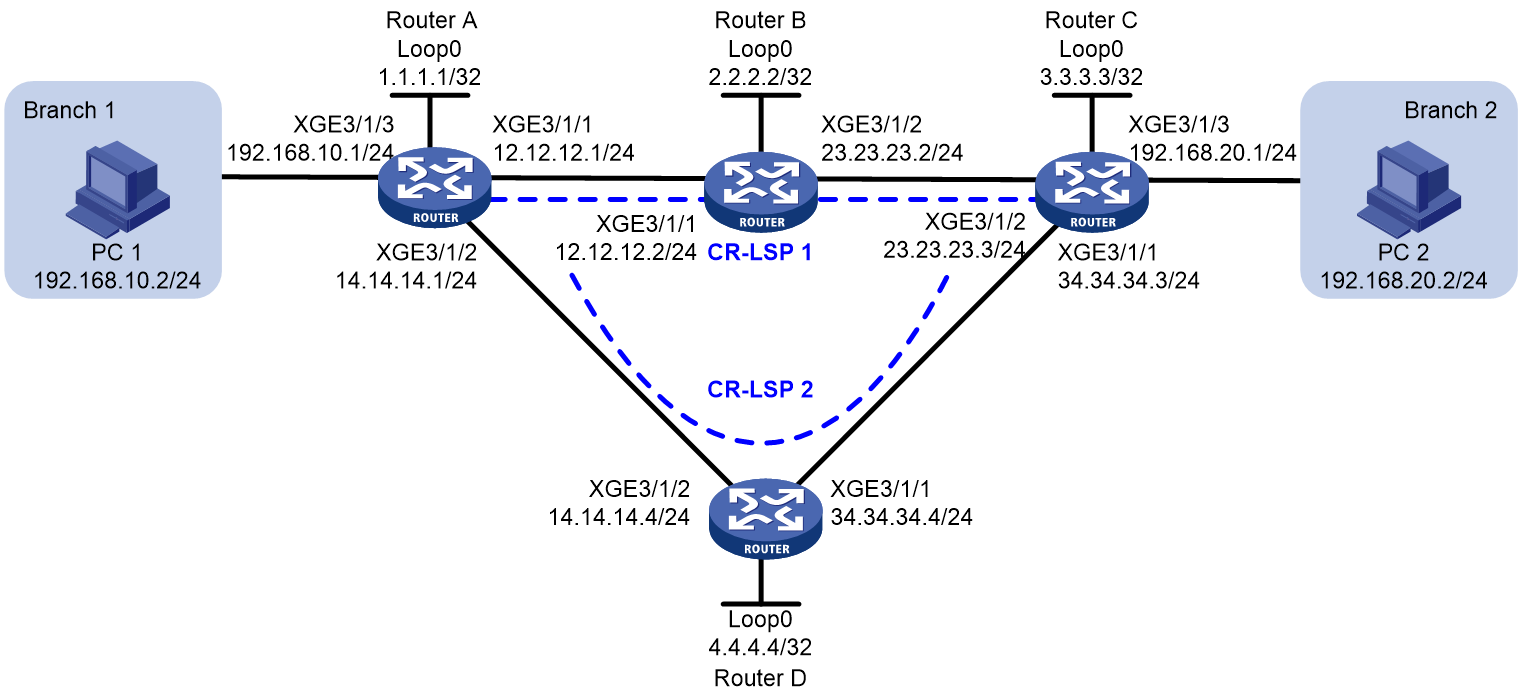
As shown in Figure 2, Branch 1 and Branch 2 of a company are connected to each other through an MPLS TE tunnel. The branches need to exchange real-time data.
To ensure high availability of the real-time service between the branches, deploy CRLSP backup for the MPLS TE tunnel to provide a primary CRLSP and a backup CRLSP. Configure BFD for the MPLS TE tunnel, so when the primary CRLSP fails, BFD can quickly detect the failure and notify RSVP of the failure to trigger a traffic switchover to the backup CRLSP.
Restrictions and guidelines
· MPLS TE cannot reserve resources and allocate labels on OSPF virtual links to establish CRLSPs. To configure OSPF TE, make sure no virtual links exist in OSPF areas.
Procedures
1. Assign IP addresses to interfaces:
# Assign an IP address to Ten-GigabitEthernet 3/1/1 on Router A.
<RouterA> system-view
[RouterA] interface ten-gigabitethernet 3/1/1
[RouterA-Ten-GigabitEthernet3/1/1] ip address 12.12.12.1 24
[RouterA-Ten-GigabitEthernet3/1/1] quit
# # Assign IP addresses to other interfaces (including the loopback interfaces) according to Figure 2. (Details not shown.)
2. Configure an LSR ID, enable MPLS, MPLS TE, and RSVP-TE on the routers:
# Configure Router A.
[RouterA] mpls te
[RouterA-te] quit
[RouterA] rsvp
[RouterA-rsvp] quit
[RouterA] interface ten-gigabitethernet 3/1/1
[RouterA-Ten-GigabitEthernet3/1/1] mpls enable
[RouterA-Ten-GigabitEthernet3/1/1] mpls te enable
[RouterA-Ten-GigabitEthernet3/1/1] rsvp enable
[RouterA-Ten-GigabitEthernet3/1/1] quit
[RouterA] interface ten-gigabitethernet 3/1/2
[RouterA-Ten-GigabitEthernet3/1/2] mpls enable
[RouterA-Ten-GigabitEthernet3/1/2] mpls te enable
[RouterA-Ten-GigabitEthernet3/1/2] rsvp enable
[RouterA-Ten-GigabitEthernet3/1/2] quit
# Configure Router B, Router C, and Router D in the same way as you configure Route A. (Details not shown.)
3. On the MPLS backbone, configure OSPF to ensure IP connectivity between the routers, enable the OSPF Opaque capability, and enable MPLS TE in OSPF area 0:
# Configure Router A.
[RouterA] ospf
[RouterA-ospf-1] opaque-capability enable
[RouterA-ospf-1] area 0
[RouterA-ospf-1-area-0.0.0.0] mpls te enable
[RouterA-ospf-1-area-0.0.0.0] network 1.1.1.1 0.0.0.0
[RouterA-ospf-1-area-0.0.0.0] network 12.12.12.0 0.0.0.255
[RouterA-ospf-1-area-0.0.0.0] network 14.14.14.0 0.0.0.255
[RouterA-ospf-1-area-0.0.0.0] network 192.168.10.0 0.0.0.255
[RouterA-ospf-1-area-0.0.0.0] quit
[RouterA-ospf-1] quit
# Configure Router B.
[RouterB] ospf
[RouterB-ospf-1] opaque-capability enable
[RouterB-ospf-1] area 0
[RouterB-ospf-1-area-0.0.0.0] mpls te enable
[RouterB-ospf-1-area-0.0.0.0] network 2.2.2.2 0.0.0.0
[RouterB-ospf-1-area-0.0.0.0] network 12.12.12.0 0.0.0.255
[RouterB-ospf-1-area-0.0.0.0] network 23.23.23.0 0.0.0.255
[RouterB-ospf-1-area-0.0.0.0] quit
[RouterB-ospf-1] quit
# Configure Router C.
[RouterC] ospf
[RouterC-ospf-1] opaque-capability enable
[RouterC ospf-1] area 0
[RouterC-ospf-1-area-0.0.0.0] mpls te enable
[RouterC-ospf-1-area-0.0.0.0] network 3.3.3.3 0.0.0.0
[RouterC ospf-1-area-0.0.0.0] network 23.23.23.0 0.0.0.255
[RouterC ospf-1-area-0.0.0.0] network 34.34.34..0 0.0.0.255
[RouterC ospf-1-area-0.0.0.0] network 192.168.20.0 0.0.0.255
[RouterC ospf-1-area-0.0.0.0] quit
[RouterC ospf-1] quit
# Configure Router D.
[RouterD] ospf
[RouterD-ospf-1] opaque-capability enable
[RouterD-ospf-1] area 0
[RouterD-ospf-1-area-0.0.0.0] mpls te enable
[RouterD-ospf-1-area-0.0.0.0] network 4.4.4.4 0.0.0.0
[RouterD-ospf-1-area-0.0.0.0] network 14.14.14.0 0.0.0.255
[RouterD-ospf-1-area-0.0.0.0] network 34.34.34.0 0.0.0.255
[RouterD-ospf-1-area-0.0.0.0] quit
[RouterD-ospf-1] quit
4. Configure the MPLS TE tunnel:
[RouterA] interface tunnel 3 mode mpls-te
[RouterA-Tunnel3] ip address 9.1.1.1 255.255.255.0
[RouterA-Tunnel3] destination 3.3.3.3
[RouterA-Tunnel3] mpls te signaling rsvp-te
[RouterA-Tunnel3] mpls te backup hot-standby
[RouterA-Tunnel3] quit
# Create explicit paths for the tunnel. Configure CR-LSP 1 as the primary path and CR-LSP 2 as the backup path by setting the preference of CR-LSP 1 to 1 and that of CR-LSP 2 to 2.
[RouterA] explicit-path cr-lsp1
[RouterA-explicit-path-cr-lsp1] nexthop 12.12.12.2
[RouterA-explicit-path-cr-lsp1] quit
[RouterA]explicit-path cr-lsp2
[RouterA-explicit-path-cr-lsp2] nexthop 14.14.14.4
[RouterA-explicit-path-cr-lsp2]quit
[RouterA] interface tunnel 3
[RouterA-Tunnel3] mpls te path preference 1 explicit-path cr-lsp1
[RouterA-Tunnel3] mpls te path preference 2 explicit-path cr-lsp2
[RouterA-Tunnel3] quit
[RouterC] interface tunnel 3 mode mpls-te
[RouterC-Tunnel3] ip address 9.3.3.3 255.255.255.0
[RouterC-Tunnel3] destination 1.1.1.1
[RouterC-Tunnel3] mpls te signaling rsvp-te
[RouterC-Tunnel3] mpls te backup hot-standby
[RouterC-Tunnel3] quit
# Create explicit paths for the tunnel. Configure CR-LSP 1 as the primary path and CR-LSP 2 as the backup path by setting the preference of CR-LSP 1 to 1 and that of CR-LSP 2 to 2.
[RouterC] explicit-path cr-lsp1
[RouterC-explicit-path-cr-lsp1] nexthop 23.23.23.2
[RouterC-explicit-path-cr-lsp1] quit
[RouterC]explicit-path cr-lsp2
[RouterC-explicit-path-cr-lsp2] nexthop 34.34.34.4
[RouterC-explicit-path-cr-lsp2]quit
[RouterC] interface tunnel 3
[RouterC-Tunnel3] mpls te path preference 1 explicit-path cr-lsp1
[RouterC-Tunnel3] mpls te path preference 2 explicit-path cr-lsp2
[RouterC-Tunnel3] quit
5. Configure a static route to direct traffic to the MPLS TE tunnel:
[RouterA] ip route-static 192.168.20.0 24 tunnel 3 preference 1
# On Router C, configure a static route to direct traffic destined for 192.168.10.0/24 to MPLS TE tunnel interface Tunnel3.
[RouterC] ip route-static 192.168.10.0 24 tunnel 3 preference 1
6. Enable BFD for MPLS, and configure BFD to verify connectivity of the MPLS TE tunnel:
# Configure Router A.
[RouterA] mpls bfd enable
[RouterA] interface tunnel 3
[RouterA-Tunnel3] mpls bfd
[RouterA-Tunnel3] quit
# Configure Router C.
[RouterC] mpls bfd enable
[RouterC] interface tunnel 3
[RouterC-Tunnel3] mpls bfd
[RouterC-Tunnel3] quit
Verifying the configuration
1. Verify that the MPLS TE tunnel has been established successfully:
# On Router A and Router C, execute the display interface tunnel command. The output shows that the tunnel state is UP. Take Router A as an example:
<RouterA> display interface tunnel
Tunnel3
Interface index: 17796
Current state: UP
Line protocol state: UP
Description: Tunnel3 Interface
Bandwidth: 64kbps
Maximum Transmit Unit: 1496
Internet Address is 9.1.1.1/24 Primary
Tunnel source unknown, destination 3.3.3.3
Tunnel TTL 255
Tunnel protocol/transport CR_LSP
Last clearing of counters: Never
Last 300 seconds input rate: 0 bytes/sec, 0 bits/sec, 0 packets/sec
Last 300 seconds output rate: 0 bytes/sec, 0 bits/sec, 0 packets/sec
Input: 0 packets, 0 bytes, 0 drops
Output: 0 packets, 0 bytes, 0 drops
2. On Router A, execute the tracert mpls te command to verify that the current path in use is CR-LSP1. (To use the tracert feature, you must also enable sending of ICMP time exceeded messages on the transit devices and enable sending of ICMP destination unreachable messages on the destination device.)
<RouterA>tracert mpls te Tunnel 3
MPLS trace route TE tunnel Tunnel3
TTL Replier Time Type Downstream
0 Ingress 12.12.12.2/[1140]
1 12.12.12.2 30 ms Transit 23.23.23.3/[3]
2 23.23.23.3 2 ms Egress
3. On Router A, execute the display mpls bfd command. The output shows that two BFD sessions have been created for the MPLS TE tunnel. The session for the primary CRLSP is up and that for the backup CRLSP is down. Take Router A as an example:
<RouterA>display mpls bfd te tunnel 3
Total number of sessions: 2, 1 up, 1 down, 0 init
FEC Type: TE Tunnel
FEC Info:
Send Addr: 1.1.1.1
End Addr: 3.3.3.3
Tunnel ID: 3
LSP ID : 1150
NHLFE ID: 1045
Local Discr: 1026 Remote Discr: -
Source IP: 1.1.1.1 Destination IP: 127.0.0.2
Session State: Down Session Role: Passive
Template Name: -
FEC Type: TE Tunnel
FEC Info:
Send Addr: 1.1.1.1
End Addr: 3.3.3.3
Tunnel ID: 3
LSP ID : 1151
NHLFE ID: 1047
Local Discr: 1027 Remote Discr: 515
Source IP: 1.1.1.1 Destination IP: 127.0.0.1
Session State: Up Session Role: Passive
Template Name: -
4. Continuously ping Router C from Router A. During this period, shut down Ten-GigabitEthernet 3/1/1 of Router B. Verify the communication between Router A and Router C.
# Continuously ping Router C from Router A.
<RouterA>ping -c 10000 -a 192.168.10.1 192.168.20.1
Ping 192.168.20.1 (192.168.20.1) from 192.168.10.1: 56 data bytes, press CTRL_C
to break
56 bytes from 192.168.20.1: icmp_seq=0 ttl=254 time=3.443 ms
56 bytes from 192.168.20.1: icmp_seq=1 ttl=254 time=2.835 ms
...
# Shut down Ten-GigabitEthernet 3/1/1 of Router B.
[RouterB] interface ten-gigabitethernet3/1/1
[RouterB-Ten-GigabitEthernet3/1/1] shutdown
# You can see that Router A and Router C resumed connectivity quickly after a short period of disconnection.
<RouterA>ping -c 10000 -a 192.168.10.1 192.168.20.1
Ping 192.168.20.1 (192.168.20.1) from 192.168.10.1: 56 data bytes, press CTRL_C
to break
56 bytes from 192.168.20.1: icmp_seq=0 ttl=254 time=3.443 ms
56 bytes from 192.168.20.1: icmp_seq=1 ttl=254 time=2.835 ms
...
56 bytes from 192.168.20.1: icmp_seq=22 ttl=254 time=3.503 ms
Request time out
56 bytes from 192.168.20.1: icmp_seq=24 ttl=254 time=2.434 ms
56 bytes from 192.168.20.1: icmp_seq=25 ttl=254 time=3.196 ms
56 bytes from 192.168.20.1: icmp_seq=26 ttl=254 time=3.592 ms
56 bytes from 192.168.20.1: icmp_seq=27 ttl=254 time=2.305 ms
56 bytes from 192.168.20.1: icmp_seq=28 ttl=254 time=2.139 ms
--- Ping statistics for 192.168.20.1 ---
29 packet(s) transmitted, 28 packet(s) received, 3.4% packet loss
round-trip min/avg/max/std-dev = 2.076/2.701/3.921/0.609 ms
5. Test whether a switchover has happened:
# On Router A, execute the tracert mpls te command. You can see the currently used path of the tunnel is CR-LSP2.
<RouterA>tracert mpls te Tunnel 3
MPLS trace route TE tunnel Tunnel3
TTL Replier Time Type Downstream
0 Ingress 14.14.14.4/[1142]
1 14.14.14.4 198 ms Transit 34.34.34.3/[3]
2 34.34.34.3 7 ms Egress
# On Router A, execute the display mpls bfd command. The output shows that a BFD session exists for the CR-LSP2 path of the tunnel and the session state is up.
<RouterA>display mpls bfd te tunnel 3
Total number of sessions: 1, 1 up, 0 down, 0 init
FEC Type: TE Tunnel
FEC Info:
Send Addr: 1.1.1.1
End Addr: 3.3.3.3
Tunnel ID: 3
LSP ID : 1151
NHLFE ID: 1047
Local Discr: 1027 Remote Discr: 515
Source IP: 1.1.1.1 Destination IP: 127.0.0.1
Session State: Up Session Role: Passive
Template Name: -
Configuration files
· Router A:
#
ospf 1
area 0.0.0.0
network 1.1.1.1 0.0.0.0
network 12.12.12.0 0.0.0.255
network 14.14.14.0 0.0.0.255
network 192.168.10.0 0.0.0.255
mpls te enable
#
mpls lsr-id 1.1.1.1
#
mpls te
#
explicit-path cr-lsp1
nexthop index 1 12.12.12.2 include strict
#
explicit-path cr-lsp2
nexthop index 1 14.14.14.4 include strict
#
rsvp
#
mpls bfd enable
#
interface LoopBack0
ip address 1.1.1.1 255.255.255.255
#
interface Ten-GigabitEthernet3/1/1
port link-mode route
ip address 12.12.12.1 255.255.255.0
mpls enable
mpls te enable
rsvp enable
#
interface Ten-GigabitEthernet3/1/2
port link-mode route
ip address 14.14.14.1 255.255.255.0
mpls enable
mpls te enable
rsvp enable
#
interface Ten-GigabitEthernet3/1/3
port link-mode route
ip address 192.168.10.1 255.255.255.0
#
interface Tunnel3 mode mpls-te
ip address 9.1.1.1 255.255.255.0
mpls te path preference 1 explicit-path cr-lsp1
mpls te path preference 2 explicit-path cr-lsp2
mpls te backup hot-standby
mpls bfd
destination 3.3.3.3
#
ip route-static 192.168.20.0 24 Tunnel3 preference 1
#
#
ospf 1
area 0.0.0.0
network 2.2.2.2 0.0.0.0
network 12.12.12.0 0.0.0.255
network 23.23.23.0 0.0.0.255
mpls te enable
#
mpls lsr-id 2.2.2.2
#
mpls te
#
rsvp
#
interface LoopBack0
ip address 2.2.2.2 255.255.255.255
#
interface Ten-GigabitEthernet3/1/1
port link-mode route
ip address 12.12.12.2 255.255.255.0
mpls enable
mpls te enable
rsvp enable
#
interface Ten-GigabitEthernet3/1/2
port link-mode route
ip address 23.23.23.2 255.255.255.0
mpls enable
mpls te enable
rsvp enable
#
· Router C:
#
ospf 1
area 0.0.0.0
network 3.3.3.3 0.0.0.0
network 23.23.23.0 0.0.0.255
network 34.34.34.0 0.0.0.255
network 192.168.20.0 0.0.0.255
mpls te enable
#
mpls lsr-id 3.3.3.3
#
mpls te
#
explicit-path cr-lsp1
nexthop index 1 23.23.23.2 include strict
#
explicit-path cr-lsp2
nexthop index 1 34.34.34.4 include strict
#
rsvp
#
mpls bfd enable
#
interface LoopBack0
ip address 3.3.3.3 255.255.255.255
#
interface Ten-GigabitEthernet3/1/1
port link-mode route
ip address 34.34.34.3 255.255.255.0
mpls enable
mpls te enable
rsvp enable
#
interface Ten-GigabitEthernet3/1/2
port link-mode route
ip address 23.23.23.3 255.255.255.0
mpls enable
mpls te enable
rsvp enable
#
interface Ten-GigabitEthernet3/1/3
port link-mode route
ip address 192.168.20.1 255.255.255.0
#
interface Tunnel3 mode mpls-te
ip address 9.3.3.3 255.255.255.0
mpls te path preference 1 explicit-path cr-lsp1
mpls te path preference 2 explicit-path cr-lsp2
mpls te backup hot-standby
mpls bfd
destination 1.1.1.1
#
ip route-static 192.168.10.0 24 Tunnel3 preference 1
#
· Router D:
#
ospf 1
area 0.0.0.0
network 4.4.4.4 0.0.0.0
network 14.14.14.0 0.0.0.255
network 34.34.34.0 0.0.0.255
mpls te enable
#
mpls lsr-id 4.4.4.4
#
mpls te
#
rsvp
#
interface LoopBack0
ip address 4.4.4.4 255.255.255.255
#
interface Ten-GigabitEthernet3/1/1
port link-mode route
ip address 34.34.34.4 255.255.255.0
mpls enable
mpls te enable
rsvp enable
#
interface Ten-GigabitEthernet3/1/2
port link-mode route
ip address 14.14.14.4 255.255.255.0
mpls enable
mpls te enable
rsvp enable
#
Related documentation
· H3C CR16000-F Routers MPLS Configuration Guide-R8385P09
· H3C CR16000-F Routers MPLS Command Reference-R8385P09
