- Table of Contents
-
- 02-Typical configuration example
- 01-AAA_Configuration_Examples
- 02-ACL_Configuration_Examples
- 03-ATM_Configuration_Examples
- 04-IGMP_Configuration_Examples
- 05-IP_Source_Guard_Configuration_Examples
- 06-Ethernet_OAM_Configuration_Examples
- 07-NQA_Configuration_Examples
- 08-QinQ_Configuration_Examples
- 09-OSPF_Configuration_Examples
- 10-MPLS_TE_Configuration_Examples
- 11-OpenFlow_Configuration_Examples
- 12-NAT_Configuration_Examples
- 13-RBAC_Configuration_Examples
- 14-IRF_Configuration_Examples
- 15-POS_Interface_Configuration_Examples
- 16-CPOS_Interface_Configuration_Examples
- 17-DLDP_Configuration_Examples
- 18-IS-IS_Configuration_Examples
- 19-MPLS_L3VPN_Configuration_Examples
- 20-SSH_Configuration_Examples
- 21-Login_Management_Configuration_Examples
- 22-SNMP_Configuration_Examples
- 23-Priority_Marking_and_Queue_Scheduling_Configuration_Examples
- 24-Multicast_VPN_Configuration_Examples
- 25-BGP_Configuration_Examples
- 26-HoVPN_Configuration_Examples
- 27-L2TP_Configuration_Examples
- 28-VRRP_Configuration_Examples
- 29-Traffic_Filtering_Configuration_Examples
- 30-Samplers_and_IPv4_NetStream_Configuration_Examples
- 31-Software_Upgrade_Examples
- 32-MPLS_L2VPN_Configuration_Examples
- 33-NetStream_Configuration_Examples
- 34-Policy-Based_Routing_Configuration_Examples
- 35-Traffic_Policing_Configuration_Examples
- 36-BFD_Configuration_Examples
- 37-OSPFv3_Configuration_Examples
- 38-VPLS_Configuration_Examples
- 39-GTS_and_Rate_Limiting_Configuration_Examples
- 40-IPv6_IS-IS_Configuration_Examples
- 41-MPLS OAM_Configuration_Examples
- 42-BGP_Route_Selection_Configuration_Examples
- 43-IS-IS_Route_Summarization_Configuration_Examples
- 44-Attack_Protection_Configuration_Examples
- Related Documents
-
| Title | Size | Download |
|---|---|---|
| 27-L2TP_Configuration_Examples | 166.72 KB |
General restrictions and guidelines
Example: Configuring client-initiated L2TP tunnels
Example: Configuring LAC-auto-initiated L2TP tunnels
Example: Configuring L2TP load balancing
Introduction
The following information provides L2TP configuration examples.
Prerequisites
Procedures and information in the following examples might be slightly different depending on the software or hardware version.
The configuration examples in this document were created and verified in a lab environment, and all the devices were started with the factory default configuration. When you are working on a live network, make sure you understand the potential impact of every command on your network.
This document assumes that you have basic knowledge of L2TP.
General restrictions and guidelines
In standard system operating mode, only some cards support this feature. For more information, see L2TP configuration in the configuration guides for your device.
In SD-WAN system operating mode, only a device with IM-SFMX cards installed supports this feature, and the device can act only as an LNS.
Example: Configuring client-initiated L2TP tunnels
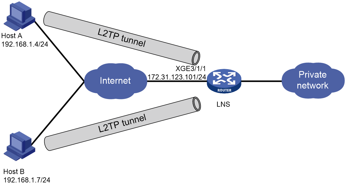
Network configuration
As shown in Figure 1, the hosts at different locations directly initiate tunneling requests to the LNS to access the private network. Configure the LNS as follows:
· Create two ISP domains to provide access services for the hosts.
· Assign the hosts to different subnets.
Prerequisites
Perform the following tasks on the hosts:
· Assign Host A to the abc.com domain, and set its computer name to hosta.abc.com.
· Assign Host B to the def.com domain, and set its computer name to hostb.def.com.
Procedures
Configuring the LNS
# Enable L2TP.
<LNS> system-view
[LNS] l2tp enable
# Enable DHCP.
[LNS] dhcp enable
# Create local BAS IP address pool pool1.
[LNS] ip pool pool1 bas local
# Set the gateway address to 10.0.1.1, and specify the DNS server at 1.1.1.1 for the IP address pool.
[LNS-ip-pool-pool1] gateway 10.0.1.1 24
[LNS-ip-pool-pool1] dns-list 1.1.1.1
# Exclude 10.0.1.1 from IP address allocation.
[LNS-ip-pool-pool1] forbidden-ip 10.0.1.1
[LNS-ip-pool-pool1] quit
# Create local BAS IP address pool pool2.
[LNS] ip pool pool2 bas local
# Set the gateway address to 10.0.2.1, and specify the DNS server at 2.2.2.2 for the IP address pool.
[LNS-ip-pool-pool2] gateway 10.0.2.1 24
[LNS-ip-pool-pool2] dns-list 2.2.2.2
# Exclude 10.0.2.1 from IP address allocation.
[LNS-ip-pool-pool2] forbidden-ip 10.0.2.1
[LNS-ip-pool-pool2] quit
# Specify domain name abc.com in local BAS IP address pool pool1, and configure local authentication for PPP users in the domain.
[LNS] domain name abc.com
[LNS-isp-abc.com] authorization-attribute ip-pool pool1
[LNS-isp-abc.com] authentication ppp local
[LNS-isp-abc.com] accounting ppp local
[LNS-isp-abc.com] quit
# Specify domain name def.com in local BAS IP address pool pool2, and configure local authentication for PPP users in the domain.
[LNS] domain name def.com
[LNS-isp-def.com] authorization-attribute ip-pool pool2
[LNS-isp-def.com] authentication ppp local
[LNS-isp-def.com] accounting ppp local
[LNS-isp-def.com] quit
# Create interface Virtual-Template 1. Configure the VT interface to authenticate the peer by using CHAP in domain abc.com.
[LNS] interface virtual-template 1
[LNS-Virtual-Template1] ppp authentication-mode chap domain abc.com
[LNS-Virtual-Template1] quit
# Create interface Virtual-Template 2. Configure the VT interface to authenticate the peer by using CHAP in domain def.com.
[LNS] interface virtual-template 2
[LNS-Virtual-Template2] ppp authentication-mode chap domain def.com
[LNS-Virtual-Template2] quit
# Assign an IP address to Ten-GigabitEthernet 3/1/1.
[LNS] interface ten-gigabitethernet 3/1/1
[LNS-Ten-GigabitEthernet3/1/1] ip address 172.31.123.101 24
[LNS-Ten-GigabitEthernet3/1/1] quit
# Create local users, set their passwords, and enable the PPP service.
[LNS] local-user user1 class network
[LNS-luser-network-user1] password simple hello
[LNS-luser-network-user1] service-type ppp
[LNS-luser-network-user1] quit
[LNS] local-user user2 class network
[LNS-luser-network-user2] password simple hello
[LNS-luser-network-user2] service-type ppp
[LNS-luser-network-user2] quit
# Create L2TP group 1 in LNS mode.
[LNS] l2tp-group 1 mode lns
# Specify Virtual-Template 1 for receiving calls from the peer named hosta.abc.com.
[LNS-l2tp1] allow l2tp virtual-template 1 remote hosta.abc.com
# Disable tunnel authentication.
[LNS-l2tp1] undo tunnel authentication
[LNS-l2tp1] quit
# Create L2TP group 2 in LNS mode.
[LNS] l2tp-group 2 mode lns
# Specify Virtual-Template 2 for receiving calls from the peer named hostb.def.com.
[LNS-l2tp2] allow l2tp virtual-template 2 remote hostb.def.com
# Disable tunnel authentication.
[LNS-l2tp2] undo tunnel authentication
[LNS-l2tp2] quit
Configuring the hosts
1. Assign IP addresses 192.168.1.4 and 192.168.1.7 to Host A and Host B, respectively.
2. Create a virtual private L2TP network connection by using the Windows system, or install the L2TP LAC client software, such as WinVPN Client. If you use any other clients, make sure the LACs and the LNS use consistent names for tunnel setup.
3. Complete the following configuration procedure (the procedure depends on the client software):
¡ Specify the PPP usernames as user1 and user2 on Host A and Host B, respectively, and set their passwords to hello.
¡ Specify the Internet interface address of the security gateway as the IP address of the LNS. In this example, the IP address is 172.31.123.101, which is used by Ten-GigabitEthernet 3/1/1 on the LNS.
¡ Modify the connection attributes: set the protocol to L2TP, the encryption attribute to customized, and the authentication mode to CHAP.
¡ Configure routes for the hosts to reach the LNS at Layer 3.
Verifying the configuration
# On the LNS, use the display l2tp tunnel command to check the established L2TP tunnels.
[LNS] display l2tp tunnel
LocalTID RemoteTID State Sessions RemoteAddress RemotePort
RemoteName
36406 13 Established 1 192.168.1.4 1701
hosta.abc.com
11556 13 Established 1 192.168.1.7 1701
hostb.def.com
Configuration files
#
dhcp enable
#
ip pool pool1 bas local
gateway 10.0.1.1 mask 255.255.255.0
dns-list 1.1.1.1
forbidden-ip 10.0.1.1
#
ip pool pool2 bas local
gateway 10.0.2.1 mask 255.255.255.0
dns-list 2.2.2.2
forbidden-ip 10.0.2.1
#
interface Virtual-Template1
ppp authentication-mode chap domain abc.com
#
interface Virtual-Template2
ppp authentication-mode chap domain def.com
#
interface ten-gigabitethernet3/1/1
ip address 172.31.123.101 255.255.255.0
#
domain name abc.com
authorization-attribute ip-pool pool1
authentication ppp local
accounting ppp local
#
domain name def.com
authorization-attribute ip-pool pool2
authentication ppp local
accounting ppp local
#
local-user user1 class network
password simple hello
service-type ppp
#
local-user user2 class network
password simple hello
service-type ppp
#
l2tp-group 1 mode lns
allow l2tp virtual-template 1 remote hosta.abc.com
undo tunnel authentication
#
l2tp-group 2 mode lns
allow l2tp virtual-template 2 remote hostb.def.com
undo tunnel authentication
#
l2tp enable
#
Example: Configuring LAC-auto-initiated L2TP tunnels
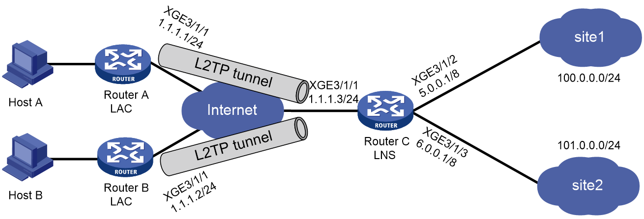
Network configuration
As shown in Figure 2, configure each LAC to establish an L2TP tunnel with the LNS in LAC-auto-initiated mode. When Host A and Host B initiate connections, they use the established tunnels to access Site 1 and Site 2, respectively.
Procedures
Configuring Router C
# Enable L2TP.
<RouterC> system-view
[RouterC] l2tp enable
# Create local users, set their passwords, and enable the PPP service.
[RouterC] local-user user1 class network
[RouterC-luser-network-user1] password simple 1234
[RouterC-luser-network-user1] service-type ppp
[RouterC-luser-network-user1] quit
[RouterC] local-user user2 class network
[RouterC-luser-network-user2] password simple 1234
[RouterC-luser-network-user2] service-type ppp
[RouterC-luser-network-user2] quit
# Configure VPN instances vpn1 and vpn2.
[RouterC] ip vpn-instance vpn1
[RouterC-vpn-instance-vpn1] route-distinguisher 100:1
[RouterC-vpn-instance-vpn1] vpn-target 100:1 import-extcommunity
[RouterC-vpn-instance-vpn1] vpn-target 100:1 export-extcommunity
[RouterC-vpn-instance-vpn1] quit
[[RouterC] ip vpn-instance vpn2
[RouterC-vpn-instance-vpn2] route-distinguisher 200:1
[RouterC-vpn-instance-vpn2] vpn-target 200:1 import-extcommunity
[RouterC-vpn-instance-vpn2] vpn-target 200:1 export-extcommunity
[RouterC-vpn-instance-vpn2] quit
# Enable DHCP.
[RouterC] dhcp enable
# Configure local BAS IP address pool pool1.
[RouterC] ip pool pool1 bas local
[RouterC-ip-pool-pool1] gateway 100.0.0.1 24
[RouterC-ip-pool-pool1] dns-list 3.3.3.3
# Exclude 100.0.0.1 from IP address allocation.
[RouterC-ip-pool-pool1] forbidden-ip 100.0.0.1
# Apply local BAS IP address pool pool1 to VPN instance vpn1.
[RouterC-ip-pool-pool1] vpn-instance vpn1
[RouterC-ip-pool-pool1] quit
# Configure local BAS IP address pool pool2.
[RouterC] ip pool pool2 bas local
[RouterC-ip-pool-pool2] gateway 101.0.0.1 24
[RouterC-ip-pool-pool2] dns-list 4.4.4.4
# Exclude 101.0.0.1 from IP address allocation.
[RouterC-ip-pool-pool2] forbidden-ip 101.0.0.1
# Apply local BAS IP address pool pool2 to VPN instance vpn2.
[RouterC-ip-pool-pool2] vpn-instance vpn2
[RouterC-ip-pool-pool2] quit
# Specify domain name abc.com in local BAS IP address pool pool1, and configure local authentication for PPP users in the domain.
[DeviceC] domain name abc.com
[DeviceC-isp-abc.com] authorization-attribute ip-pool pool1
[DeviceC-isp-abc.com] authentication ppp local
[DeviceC-isp-abc.com] quit
# Specify domain name def.com in local BAS IP address pool pool2, and configure local authentication for PPP users in the domain.
[DeviceC] domain name def.com
[DeviceC-isp-def.com] authorization-attribute ip-pool pool2
[DeviceC-isp-def.com] authentication ppp local
[DeviceC-isp-def.com] quit
# Create interface Virtual-Template 1.
[RouterC] interface virtual-template 1
# Configure the VT interface to authenticate the peer by using PAP in domain abc.com.
[RouterC-Virtual-Template1] ppp authentication-mode pap domain abc.com
# Associate Virtual-Template 1 with VPN instance vpn1.
[RouterC-Virtual-Template1] ip binding vpn-instance vpn1
[RouterC-Virtual-Template1] quit
# Create interface Virtual-Template 2.
[RouterC] interface virtual-template 2
# Configure the VT interface to authenticate the peer by using PAP in domain def.com.
[RouterC-Virtual-Template2] ppp authentication-mode pap domain def.com
# Associate Virtual-Template 2 with VPN instance vpn2.
[RouterC-Virtual-Template2] ip binding vpn-instance vpn2
[RouterC-Virtual-Template2] quit
# Create L2TP group 1 in LNS mode.
[RouterC] l2tp-group 1 mode lns
[RouterC-l2tp1] tunnel name lns-A
[RouterC-l2tp1] undo tunnel authentication
[RouterC-l2tp1] allow l2tp virtual-template 1 remote lac-A
[RouterC-l2tp1] quit
# Create L2TP group 2 in LNS mode.
[RouterC] l2tp-group 2 mode lns
# Configure the local tunnel name as lns-B, and specify Virtual-Template 2 for receiving tunneling requests from lac-B.
[RouterC-l2tp2] tunnel name lns-B
[RouterC-l2tp2] undo tunnel authentication
[RouterC-l2tp2] allow l2tp virtual-template 2 remote lac-B
[RouterC-l2tp2] quit
# Assign IP addresses to interfaces, and associate interfaces with VPN instances.
[RouterC] interface ten-gigabitethernet 3/1/1
[RouterC-Ten-GigabitEthernet3/1/1] ip address 1.1.1.3 24
[RouterC-Ten-GigabitEthernet3/1/1] quit
[RouterC] interface ten-gigabitethernet 3/1/2
[RouterC-Ten-GigabitEthernet3/1/2] ip binding vpn-instance vpn1
[RouterC-Ten-GigabitEthernet3/1/2] ip address 5.0.0.1 8
[RouterC-Ten-GigabitEthernet3/1/2] quit
[RouterC] interface ten-gigabitethernet 3/1/3
[RouterC-Ten-GigabitEthernet3/1/3] ip binding vpn-instance vpn2
[RouterC-Ten-GigabitEthernet3/1/3] ip address 6.0.0.1 8
[RouterC-Ten-GigabitEthernet3/1/3] quit
Configuring Router A
# Enable L2TP.
<RouterA> system-view
[RouterA] l2tp enable
# Create L2TP group 1 in LAC mode.
[RouterA] l2tp-group 1 mode lac
# Configure the local tunnel name as lac-A, and specify the IP address of the tunnel peer (LNS).
[RouterA-l2tp1] tunnel name lac-A
[RouterA-l2tp1] undo tunnel authentication
[RouterA-l2tp1] lns-ip 1.1.1.3
[RouterA-l2tp1] quit
# Create Virtual-PPP 1. Configure its username and password as user1 and 1234 and PPP authentication as PAP.
[RouterA] interface virtual-PPP 1
[RouterA-Virtual-PPP1] ip address ppp-negotiate
[RouterA-Virtual-PPP1] ppp pap local-user user1 password simple 1234
[RouterA-Virtual-PPP1] quit
# Assign an IP address to Ten-GigabitEthernet 3/1/1.
[RouterA] interface ten-gigabitethernet 3/1/1
[RouterA-Ten-GigabitEthernet3/1/1] ip address 1.1.1.1 24
[RouterA-Ten-GigabitEthernet3/1/1] quit
[RouterA] ip route-static 5.0.0.0 8 Virtual-PPP 1
# Trigger the LAC to establish an L2TP tunnel with the LNS.
[RouterA] interface virtual-PPP 1
[RouterA-Virtual-PPP1] l2tp-auto-client l2tp-group 1
[RouterA-Virtual-PPP1] quit
Configuring Router B
# Enable L2TP.
<RouterB> system-view
[RouterB] l2tp enable
# Create L2TP group 1 in LAC mode.
[RouterB] l2tp-group 1 mode lac
# Configure the local tunnel name as lac-B, and specify the IP address of the tunnel peer (LNS).
[RouterB-l2tp1] tunnel name lac-B
[RouterB-l2tp1] undo tunnel authentication
[RouterB-l2tp1] lns-ip 1.1.1.3
[RouterB-l2tp1] quit
# Create Virtual-PPP 1. Configure its username and password as user2 and 1234 and PPP authentication as PAP.
[RouterB] interface virtual-PPP 1
[RouterB-Virtual-PPP1] ip address ppp-negotiate
[RouterB-Virtual-PPP1] ppp pap local-user user2 password simple 1234
[RouterB-Virtual-PPP1] quit
# Assign an IP address to Ten-GigabitEthernet 3/1/1.
[RouterB] interface ten-gigabitethernet 3/1/1
[RouterB-Ten-GigabitEthernet3/1/1] ip address 1.1.1.2 24
[RouterB-Ten-GigabitEthernet3/1/1] quit
# Configure a static route so that packets destined for Site 2 will be forwarded through the L2TP tunnel.
[RouterB] ip route-static 6.0.0.0 8 virtual-PPP 1
# Trigger the LAC to establish an L2TP tunnel with the LNS.
[RouterB] interface virtual-PPP 1
[RouterB-Virtual-PPP1] l2tp-auto-client l2tp-group 1
[RouterB-Virtual-PPP1] quit
Verifying the configuration
# On Router A, verify that Virtual-PPP 1 has obtained an IP address from local BAS IP address pool pool1.
[RouterA] display interface virtual-ppp 1 brief
Brief information on interfaces in route mode:
Link: ADM - administratively down; Stby - standby
Protocol: (s) - spoofing
Interface Link Protocol Primary IP Description
VPPP1 UP UP 100.0.0.2
# On Router B, verify that Virtual-PPP 1 has obtained an IP address from local BAS IP address pool pool2.
[RouterB] display interface virtual-ppp 1 brief
Brief information on interfaces in route mode:
Link: ADM - administratively down; Stby - standby
Protocol: (s) - spoofing
Interface Link Protocol Primary IP Description
VPPP1 UP UP 101.0.0.2
# Verify that Router A can ping 5.0.0.1 on Router C through the L2TP tunnel.
[RouterA] ping -a 100.0.0.2 5.0.0.1
Ping 5.0.0.1 (5.0.0.1): 56 data bytes, press CTRL_C to break
56 bytes from 5.0.0.1: icmp_seq=0 ttl=128 time=0.452 ms
56 bytes from 5.0.0.1: icmp_seq=1 ttl=128 time=0.625 ms
56 bytes from 5.0.0.1: icmp_seq=2 ttl=128 time=0.673 ms
56 bytes from 5.0.0.1: icmp_seq=3 ttl=128 time=0.687 ms
56 bytes from 5.0.0.1: icmp_seq=4 ttl=128 time=0.679 ms
--- Ping statistics for 5.0.0.1 ---
5 packets transmitted, 5 packets received, 0.0% packet loss
round-trip min/avg/max/std-dev = 0.452/0.623/0.687/0.088 ms
# Verify that Router B can ping 6.0.0.1 on Router C through the L2TP tunnel.
[RouterB] ping 6.0.0.1
Ping 6.0.0.1 (6.0.0.1): 56 data bytes, press CTRL_C to break
56 bytes from 6.0.0.1: icmp_seq=0 ttl=128 time=0.452 ms
56 bytes from 6.0.0.1: icmp_seq=1 ttl=128 time=0.625 ms
56 bytes from 6.0.0.1: icmp_seq=2 ttl=128 time=0.673 ms
56 bytes from 6.0.0.1: icmp_seq=3 ttl=128 time=0.687 ms
56 bytes from 6.0.0.1: icmp_seq=4 ttl=128 time=0.679 ms
--- Ping statistics for 6.0.0.1 ---
5 packets transmitted, 5 packets received, 0.0% packet loss
round-trip min/avg/max/std-dev = 0.452/0.623/0.687/0.088 ms
Configuration files
· Router C:
#
ip vpn-instance vpn1
route-distinguisher 100:1
vpn-target 100:1 import-extcommunity
vpn-target 100:1 export-extcommunity
#
ip vpn-instance vpn2
route-distinguisher 200:1
vpn-target 200:1 import-extcommunity
vpn-target 200:1 export-extcommunity
#
dhcp enable
#
ip pool pool1 bas local
vpn-instance vpn1
gateway 100.0.0.1 mask 255.255.255.0
dns-list 3.3.3.3
forbidden-ip 100.0.0.1
#
ip pool pool2 bas local
vpn-instance vpn2
gateway 101.0.0.1 mask 255.255.255.0
dns-list 4.4.4.4
forbidden-ip 101.0.0.1
#
interface Virtual-Template1
ppp authentication-mode pap domain abc.com
ip binding vpn-instance vpn1
#
interface Virtual-Template2
ppp authentication-mode pap
ip binding vpn-instance vpn2
#
interface ten-gigabitethernet3/1/1
ip address 1.1.1.3 255.255.255.0
#
interface ten-gigabitethernet3/1/2
ip binding vpn-instance vpn1
ip address 5.0.0.1 255.0.0.0
#
interface ten-gigabitethernet3/1/3
ip binding vpn-instance vpn2
ip address 6.0.0.1 255.0.0.0
#
local-user user1 class network
password cipher $c$3$Wf7ut8Li9ryKmOvk53vSKPHvBQHOu8w=
service-type ppp
#
local-user user2 class network
password cipher $c$3$rpUZj85qaeXDflgm1P5af58Kj/maHXM=
service-type ppp
#
l2tp-group 1 mode lns
allow l2tp virtual-template 1 remote lac-A
undo tunnel authentication
tunnel name lns-A
#
l2tp-group 2 mode lns
allow l2tp virtual-template 2 remote lac-B
tunnel name lns-B
#
l2tp enable
#
domain name abc.com
authorization-attribute ip-pool pool1
authentication ppp local
#
domain name def.com
authorization-attribute ip-pool pool2
authentication ppp local
#
· Router A:
#
interface Virtual-PPP1
ppp pap local-user user1 password cipher $c$3$CYBBKjOoTx2nLdklyFk5zUtfXOKC5f8=
ip address ppp-negotiate
l2tp-auto-client l2tp-group 1
#
interface ten-gigabitethernet3/1/1
ip address 1.1.1.1 255.255.255.0
#
ip route-static 5.0.0.0 8 Virtual-PPP1
#
l2tp-group 1 mode lac
lns-ip 1.1.1.3
undo tunnel authentication
tunnel name lac-A
#
l2tp enable
#
· Router B:
#
interface Virtual-PPP1
ppp pap local-user user2 password cipher $c$3$w9MwmqfWlBN/bbkspWTwTE9V3Zxe6Sk=
ip address ppp-negotiate
l2tp-auto-client l2tp-group 1
#
interface ten-gigabitethernet3/1/1
ip address 1.1.1.2 255.255.255.0
#
ip route-static 6.0.0.0 8 Virtual-PPP1
#
l2tp-group 1 mode lac
lns-ip 1.1.1.3
undo tunnel authentication
tunnel name lac-B
#
l2tp enable
#
Example: Configuring L2TP load balancing
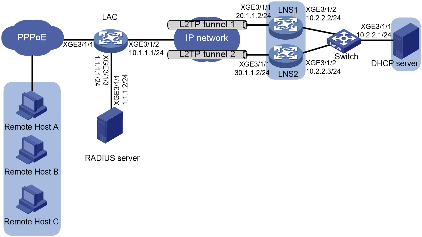
Network configuration
As shown in Figure 3, configure the LAC to establish an L2TP tunnel with each LNS for the hosts to access the private networks attached to the LNSs through PPPoE. Configure the LAC to perform weighted load balancing over the L2TP tunnels.
Restrictions and guidelines
This example uses a RADIUS server to deliver tunnel attributes to the LAC. You also can configure L2TP load balancing at the CLI on the LAC.
You can use a RADIUS server to issue tunnel attributes for L2TP load balancing only when users use the same username and password, and only 1:1 load balancing is supported in this condition.
Prerequisites
# Assign IP addresses to interfaces as shown in Figure 3. (Details not shown.)
# Configure routing settings for the LAC to communicate with the LNSs and RADIUS server. (Details not shown.)
Procedures
Configuring the RADIUS server
|
|
NOTE: This example uses a FreeRADIUS server that runs on Linux. |
# Add the RADIUS client IP address and shared key to the clients.conf configuration file.
client 1.1.1.1/32 {
ipaddr = 1.1.1.1
netmask=32
secret = 123
}
# Add PPP user configuration to the users file.
user1 Cleartext-Password := "pass1"
Service-Type = Framed-User,
Framed-Protocol = PPP,
h3c-Remanent-Volume = "1",
Session-timeout =60,
Tunnel-Server-Endpoint:30 = "20.1.1.2 30.1.1.2",
Tunnel-Medium-Type:30 = IPv4,
Tunnel-Client-Auth-Id:30 = "LAC",
Tunnel-Type:30 = L2TP,
Tunnel-Password:30 = aabbcc,
When an L2TP user dials into the LAC, the LAC as a RADIUS client will submit user identity information to the RADIUS server. Then, the RADIUS server authenticates the user, returns the authentication result, and issues the tunnel attributes in Table 1 to the LAC for it to set up L2TP tunnels and sessions.
Table 1 Tunnel attributes issued to an LAC by a RADIUS server
|
Attribute No. |
Attribute |
Description |
|
64 |
Tunnel-Type |
Tunnel type. Only L2TP is supported. |
|
65 |
Tunnel-Medium-Type |
Tunnel medium type. Only IPv4 is supported. |
|
67 |
Tunnel-Server-Endpoint |
LNS IP address. Multiple IP addresses indicate 1:1 load balancing. |
|
69 |
Tunnel-Password |
Tunnel password. |
|
90 |
Tunnel-Client-Auth-Id |
LAC-end tunnel name. |
Configuring the LAC
# Create RADIUS scheme rs1 and enter its view.
<LAC> system-view
[LAC] radius scheme rs1
# Specify the primary authentication and accounting servers, and set the shared key for secure RADIUS authentication and accounting communication.
[LAC-radius-rs1] primary authentication 1.1.1.2
[LAC-radius-rs1] primary accounting 1.1.1.2
[LAC-radius-rs1] key authentication simple 123
[LAC-radius-rs1] key accounting simple 123
[LAC-radius-rs1] quit
# Configure the LAC to remove the domain name from the username sent to the RADIUS server.
[LAC] user-name-format without-domain
# Create interface Virtual-Template 1. Configure the VT interface to authenticate the peer by using PAP in domain dm1.
[LAC] interface virtual-template 1
[LAC-Virtual-Template1] ppp authentication-mode pap domain dm1
[LAC-Virtual-Template1] quit
# Configure ISP domain dm1 to apply RADIUS scheme rs1 to PPP users.
[LAC] domain name dm1
[LAC-isp-dm1] authentication ppp radius-scheme rs1
[LAC-isp-dm1] accounting ppp radius-scheme rs1
[LAC-isp-dm1] authorization ppp radius-scheme rs1
[LAC-isp-dm1] quit
# Enable the PPPoE server on Ten-GigabitEthernet 3/1/1 and bind the interface to Virtual-Template 1.
[LAC] interface ten-gigabitethernet 3/1/1
[LAC-Ten-GigabitEthernet3/1/1] pppoe-server bind virtual-template 1
[LAC-Ten-GigabitEthernet3/1/1] quit
# Enable L2TP.
[LAC] l2tp enable
Configuring LNS 1
# Create local user user1, set its password, and enable the PPP service.
<LNS1> system-view
[LNS1] local-user user1 class network
[LNS1-luser-network-user1] password simple pass1
[LNS1-luser-network-user1] service-type ppp
[LNS1-luser-network-user1] quit
# Enable DHCP.
[LNS1] dhcp enable
# Enable recording client information in DHCP relay entries.
[LNS1] dhcp relay client-information record
# Create remote BAS IP address pool pool1. Set the gateway address to 192.168.1.1. Exclude IP address 192.168.1.1 from IP address allocation. Specify the remote DHCP server at 10.2.2.1 for the address pool.
[LNS1] ip pool pool1 bas remote
[LNS1-ip-pool-pool1] gateway 192.168.1.1 25
[LNS1-ip-pool-pool1] forbidden-ip 192.168.1.1
[LNS1-ip-pool-pool1] remote-server 10.2.2.1
[LNS1-ip-pool-pool1] quit
# Configure ISP domain dm1 to perform local authentication, accounting, and authorization for PPP users and apply address pool pool1 to the PPP users.
[LNS1] domain name dm1
[LNS1-isp-dm1] authentication ppp local
[LNS1-isp-dm1] accounting ppp local
[LNS1-isp-dm1] authorization ppp local
[LNS1-isp-dm1] authorization-attribute ip-pool pool1
[LNS1-isp-dm1] quit
# Create interface Virtual-Template 1. Configure the VT interface to authenticate the peer by using PAP in domain dm1.
[LNS1] interface virtual-template 1
[LNS1-virtual-template1] ppp authentication-mode pap domain dm1
[LNS1-virtual-template1] quit
# Enable L2TP.
[LNS1] l2tp enable
# Create L2TP group 1 in LNS mode.
[LNS1] l2tp-group 1 mode lns
# Configure the local tunnel name as LNS1, and specify Virtual-Template 1 for receiving calls from the LAC.
[LNS1-l2tp1] tunnel name LNS1
[LNS1-l2tp1] allow l2tp virtual-template 1 remote LAC
# Enable tunnel authentication, and specify the tunnel authentication key as aabbcc.
[LNS1-l2tp1] tunnel authentication
[LNS1-l2tp1] tunnel password simple aabbcc
[LNS1-l2tp1] quit
Configuring LNS 2
# Create local user user1, set its password, and enable the PPP service.
<LNS2> system-view
[LNS2] local-user user1 class network
[LNS2-luser-network-user1] password simple pass1
[LNS2-luser-network-user1] service-type ppp
[LNS2-luser-network-user1] quit
# Enable DHCP.
[LNS2] dhcp enable
# Enable recording client information in DHCP relay entries.
[LNS2] dhcp relay client-information record
# Create remote BAS IP address pool pool2. Set the gateway address to 192.168.1.129. Exclude IP address 192.168.1.129 from IP address allocation. Specify the remote DHCP server at 10.2.2.1 for the address pool.
[LNS2] ip pool pool2 bas remote
[LNS2-ip-pool-pool2] gateway 192.168.1.129 25
[LNS2-ip-pool-pool2] forbidden-ip 192.168.1.129
[LNS2-ip-pool-pool2] remote-server 10.2.2.1
[LNS2-ip-pool-pool2] quit
# Configure ISP domain dm1 to perform local authentication, accounting, and authorization for PPP users and apply address pool pool1 to the PPP users.
[LNS2] domain name dm1
[LNS2-isp-dm1] authentication ppp local
[LNS2-isp-dm1] accounting ppp local
[LNS2-isp-dm1] authorization ppp local
[LNS2-isp-dm1] authorization-attribute ip-pool pool2
[LNS2-isp-dm1] quit
# Create interface Virtual-Template 1. Configure the VT interface to authenticate the peer by using PAP in domain dm1.
[LNS2] interface virtual-template 1
[LNS2-virtual-template1] ppp authentication-mode pap domain dm1
[LNS2-virtual-template1] quit
# Enable L2TP.
[LNS2] l2tp enable
# Create L2TP group 1 in LNS mode.
[LNS2] l2tp-group 1 mode lns
# Configure the local tunnel name as LNS2, and specify Virtual-Template 1 for receiving calls from the LAC.
[LNS2-l2tp1] tunnel name LNS2
[LNS2-l2tp1] allow l2tp virtual-template 1 remote LAC
# Enable tunnel authentication, and specify the tunnel authentication key as aabbcc.
[LNS2-l2tp1] tunnel authentication
[LNS2-l2tp1] tunnel password simple aabbcc
[LNS2-l2tp1] quit
Configuring the DHCP server
# Enable DHCP.
<DHCP> system-view
[DHCP] dhcp enable
# Configure common IP address pool pool1.
[DHCP] ip pool pool1
[DHCP-ip-pool-pool1] network 192.168.1.0 25
[DHCP-ip-pool-pool1] gateway-list 192.168.1.1
[DHCP-ip-pool-pool1] dns-list 8.8.8.8
# Exclude 192.168.1.1 from IP address allocation.
[DHCP-ip-pool-pool1] forbidden-ip 192.168.1.1
[DHCP-ip-pool-pool1] quit
# Configure common IP address pool pool2.
[DHCP] ip pool pool2
[DHCP-ip-pool-pool2] network 192.168.1.128 25
[DHCP-ip-pool-pool2] gateway-list 192.168.1.129
[DHCP-ip-pool-pool2] dns-list 8.8.8.8
# Exclude 192.168.1.1 from IP address allocation.
[DHCP-ip-pool-pool2] forbidden-ip 192.168.1.129
[DHCP-ip-pool-pool2] quit
# Configure static routes to the LAC.
[DHCP] ip route-static 192.168.1.0 255.255.255.128 10.2.2.2
[DHCP] ip route-static 192.168.1.128 255.255.255.128 10.2.2.3
Configuring the hosts
# On the hosts, enter username user1 and password pass1 in the dial-up network window to dial a PPPoE connection.
Verifying the configuration
# Verify that Host A, Host B, and Host C have obtained IP addresses 192.168.1.2, 192.168.1.130. and 192.168.1.3, and they can ping the gateway.
# On LNS 1 and LNS 2, use the use the display l2tp session command to check the established L2TP sessions.
[LNS1] display l2tp session
LocalSID RemoteSID LocalTID State
Username
49545 10341 22365 Established
user1
24517 50848 22365 Established
user1
[LNS2] display l2tp session
LocalSID RemoteSID LocalTID State
Username
21869 45683 29701 Established
user1
# On the LAC, use the display l2tp tunnel command to check the established L2TP tunnels.
[LAC] display l2tp tunnel
LocalTID RemoteTID State Sessions RemoteAddress RemotePort
RemoteName
2349 22365 Established 2 20.1.1.2 1701
LNS1
47731 29701 Established 1 30.1.1.2 1701
LNS2
Configuration files
· LAC:
#
interface Virtual-Template1
ppp authentication-mode pap domain dm1
ip address 10.0.0.1 255.255.255.0
#
interface ten-gigabitethernet3/1/1
pppoe-server bind virtual-template 1
pppoe-server access-line-id content all
#
interface ten-gigabitethernet3/1/2
ip address 10.1.1.1 255.255.255.0
#
interface ten-gigabitethernet3/1/3
ip address 1.1.1.1 255.255.255.0
#
ip route-static 0.0.0.0 0 10.1.1.2
#
radius scheme rs1
primary authentication 1.1.1.2
primary accounting 1.1.1.2
key authentication cipher $c$3$JWv9UgkAq9zqCA/zIgiY+2CNEa/y5w==
key accounting cipher $c$3$G+VGeU3QNguXqt2JfJhppzWUI/9S5w==
#
l2tp enable
· LNS 1:
#
dhcp enable
#
local-user user1 class network
password simple pass1
service-type ppp
#
ip pool pool1 bas remote
gateway 192.168.1.1 mask 255.255.255.128
forbidden-ip 192.168.1.1
remote-server 10.2.2.1
#
interface Virtual-Template1
ppp authentication-mode pap domain dm1
#
interface ten-gigabitethernet3/1/1
ip address 20.1.1.2 255.255.255.0
#
interface ten-gigabitethernet3/1/2
ip address 10.2.2.2 255.255.255.0
#
ip route-static 0.0.0.0 0 20.1.1.1
#
domain name dm1
authentication ppp local
accounting ppp local
authorization ppp local
authorization-attribute ip-pool pool1
#
l2tp-group 1 mode lns
allow l2tp virtual-template 1 remote LAC
tunnel authentication
tunnel password simple aabbcc
tunnel name LNS
#
l2tp enable
· LNS 2:
#
dhcp enable
#
local-user user1 class network
password simple pass1
service-type ppp
#
ip pool pool2 bas remote
gateway 192.168.1.129 mask 255.255.255.128
forbidden-ip 192.168.1.129
remote-server 10.2.2.1
#
interface Virtual-Template1
ppp authentication-mode pap domain dm1
#
interface ten-gigabitethernet3/1/1
ip address 30.1.1.2 255.255.255.0
#
domain name dm1
authentication ppp local
accounting ppp local
authorization ppp local
authorization-attribute ip-pool pool2
#
interface ten-gigabitethernet3/1/2
ip address 10.2.2.3 255.255.255.0
#
ip route-static 0.0.0.0 0 30.1.1.1
#
l2tp-group 1 mode lns
allow l2tp virtual-template 1 remote LAC
tunnel authentication
tunnel password simple aabbcc
tunnel name LNS
#
l2tp enable
· DHCP server:
#
dhcp enable
#
ip pool pool1
gateway-list 192.168.1.1
network 192.168.1.0 mask 255.255.255.128
forbidden-ip 192.168.1.1
#
ip pool pool2
gateway-list 192.168.1.128
network 192.168.1.129 mask 255.255.255.128
forbidden-ip 192.168.1.129
#
interface ten-gigabitethernet3/1/1
ip address 10.2.2.1 255.255.255.0
#
ip route-static 192.168.1.0 25 10.2.2.2
ip route-static 192.168.1.128 25 10.2.2.3
Related documentation
· H3C CR16000-F Routers BRAS Services Configuration Guide-R8385P09
· H3C CR16000-F Routers BRAS Services Command Reference-R8385P09
·
