- Table of Contents
-
- 02-Typical configuration example
- 01-AAA_Configuration_Examples
- 02-ACL_Configuration_Examples
- 03-ATM_Configuration_Examples
- 04-IGMP_Configuration_Examples
- 05-IP_Source_Guard_Configuration_Examples
- 06-Ethernet_OAM_Configuration_Examples
- 07-NQA_Configuration_Examples
- 08-QinQ_Configuration_Examples
- 09-OSPF_Configuration_Examples
- 10-MPLS_TE_Configuration_Examples
- 11-OpenFlow_Configuration_Examples
- 12-NAT_Configuration_Examples
- 13-RBAC_Configuration_Examples
- 14-IRF_Configuration_Examples
- 15-POS_Interface_Configuration_Examples
- 16-CPOS_Interface_Configuration_Examples
- 17-DLDP_Configuration_Examples
- 18-IS-IS_Configuration_Examples
- 19-MPLS_L3VPN_Configuration_Examples
- 20-SSH_Configuration_Examples
- 21-Login_Management_Configuration_Examples
- 22-SNMP_Configuration_Examples
- 23-Priority_Marking_and_Queue_Scheduling_Configuration_Examples
- 24-Multicast_VPN_Configuration_Examples
- 25-BGP_Configuration_Examples
- 26-HoVPN_Configuration_Examples
- 27-L2TP_Configuration_Examples
- 28-VRRP_Configuration_Examples
- 29-Traffic_Filtering_Configuration_Examples
- 30-Samplers_and_IPv4_NetStream_Configuration_Examples
- 31-Software_Upgrade_Examples
- 32-MPLS_L2VPN_Configuration_Examples
- 33-NetStream_Configuration_Examples
- 34-Policy-Based_Routing_Configuration_Examples
- 35-Traffic_Policing_Configuration_Examples
- 36-BFD_Configuration_Examples
- 37-OSPFv3_Configuration_Examples
- 38-VPLS_Configuration_Examples
- 39-GTS_and_Rate_Limiting_Configuration_Examples
- 40-IPv6_IS-IS_Configuration_Examples
- 41-MPLS OAM_Configuration_Examples
- 42-BGP_Route_Selection_Configuration_Examples
- 43-IS-IS_Route_Summarization_Configuration_Examples
- 44-Attack_Protection_Configuration_Examples
- Related Documents
-
| Title | Size | Download |
|---|---|---|
| 16-CPOS_Interface_Configuration_Examples | 97.57 KB |
Introduction
This document provides CPOS-E1 channel configuration examples.
Prerequisites
The configuration examples in this document were created and verified in a lab environment, and all the devices were started with the factory default configuration. When you are working on a live network, make sure you understand the potential impact of every command on your network.
This document assumes that you have basic knowledge of CPOS interface, E1, and MP.
Restrictions and guidelines
MP supports binding interfaces on the same LPU rather than on different LPUs. MP binding on different subcards on the same LPU is not supported.
Only subcards MIC-ET16L, MIC-CLP2L, and MIC-CLP4L support MP binding.
Example: Configuring CPOS-E1 channels
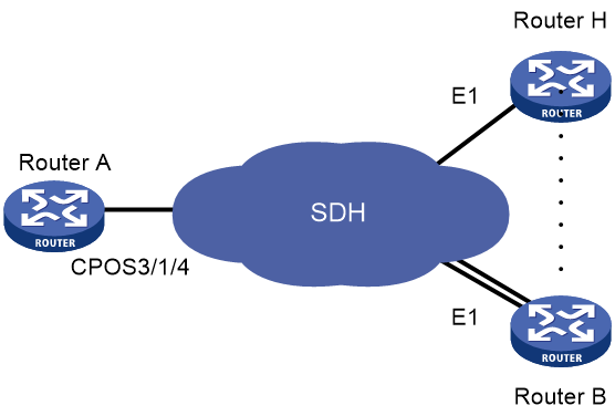
Network configuration
As shown in Figure 1, branch nodes Router B through Router H are uplinked to the central node Router A through E1 links. Router A aggregates these E1 links by using a CPOS interface.
Add one additional E1 link on Router B to expand its capacity, and use an MP-group interface to bind the two E1 links.
Restrictions and guidelines
For correct network synchronization, make sure the master clock mode is configured on the SONET/SDH devices connected to the routers.
Procedures
Configuring Router A
# Configure E1 channels 1 and 2 of CPOS 3/1/4 to operate in unframed mode.
[RouterA] controller cpos 3/1/4
[RouterA-Cpos3/1/4] e1 1 unframed
[RouterA-Cpos3/1/4] e1 2 unframed
# Create MP-group 3/1/1 and assign an IP address to it.
[RouterA] interface mp-group 3/1/1
[RouterA-Mp-group3/1/1] ip address 10.1.1.1 24
[RouterA-Mp-group3/1/1] quit
# Assign Serial 3/1/4/1:0 to MP-group interface 3/1/1.
[RouterA] interface serial3/1/4/1:0
[RouterA-Serial3/1/4/1:0] ppp mp mp-group 3/1/1
[RouterA-Serial3/1/4/1:0] quit
# Assign Serial 3/1/4/2:0 to MP-group interface 3/1/1.
[RouterA] interface serial3/1/4/2:0
[RouterA-Serial3/1/4/2:0] ppp mp mp-group 3/1/1
[RouterA-Serial3/1/4/2:0] quit
Configuring Router B
# Configure E1 3/1/10 to operate in E1 mode.
<RouterB> system-view
[RouterB] controller e1 3/1/10
[RouterB-E1 3/1/10] using e1
[RouterB-E1 3/1/10] quit
# Configure E1 3/1/8 to operate in E1 mode.
[RouterB] controller e1 3/1/8
[RouterB-E1 3/1/8] using e1
[RouterB-E1 3/1/8] quit
# Create MP-group 3/1/1 and assign an IP address to it.
[RouterB] interface mp-group 3/1/1
[RouterB-Mp-group3/1/1] ip address 10.1.1.2 24
[RouterB-Mp-group3/1/1] quit
# Assign Serial 3/1/10:0 to MP-group interface 3/1/1.
[RouterB] interface serial3/1/10:0
[RouterB-Serial3/1/10:0] ppp mp mp-group 3/1/1
[RouterB-Serial3/1/10:0] quit
# Assign Serial 3/1/8:0 to MP-group interface 3/1/1.
[RouterB] interface serial3/1/8:0
[RouterB-Serial3/1/8:0] ppp mp mp-group 3/1/1
[RouterB-Serial3/1/8:0] quit
Verifying the configuration
1. Verify the MP interface configuration and state on Router A and Router B.
# Display detailed information about MP-group interface 3/1/1 on Router A.
[RouterA] display interface mp-group 3/1/1
MP-group3/1/1
Current state: UP
Line protocol state: UP
Description: MP-group3/1/1 Interface
Bandwidth: 1024kbps
Maximum transmit unit: 1500
Hold timer: 10 seconds, retry times: 5
Internet Address is 10.1.1.1/24 (primary)
Link layer protocol: PPP
LCP: opened, MP: opened, IPCP: opened, OSICP: opened, MPLSCP: opened, IPv6CP: op
ened
Physical: MP, baudrate: 1024000 bps
Last link flapping: Never
Last clearing of counters: Never
Last 5 seconds input rate: 14 bytes/sec, 112 bits/sec, 0 packets/sec
Last 5 seconds output rate: 14 bytes/sec, 112 bits/sec, 0 packets/sec
Input: 73 packets, 24764 bytes, 0 drops
Output: 62 packets, 24882 bytes, 0 drops
The output shows that the MP-group interface on Router A is up.
# Display detailed information about MP-group interface 3/1/1 on Router B.
[RouterB] display interface mp-group 3/1/1
MP-group3/1/1
Current state: UP
Line protocol state: UP
Description: MP-group3/1/1 Interface
Bandwidth: 1024kbps
Maximum transmit unit: 1500
Hold timer: 10 seconds, retry times: 5
Internet Address is 10.1.1.2/24 (primary)
Link layer protocol: PPP
LCP: opened, MP: opened, IPCP: opened, OSICP: opened, MPLSCP: opened, IPv6CP: opened
Physical: MP, baudrate: 1024000 bps
Last link flapping: Never
Last clearing of counters: Never
Last 10 seconds input rate: 374 bytes/sec, 2992 bits/sec, 1 packets/sec
Last 10 seconds output rate: 293 bytes/sec, 2344 bits/sec, 0 packets/sec
Input: 39 packets, 12301 bytes, 0 drops
Output: 37 packets, 11824 bytes, 0 drops
The output shows that the MP-group interface on Router B is up.
2. Verify that the MP-group interface configuration on Router A and Router B.
# Display MP information on MP-group interface 3/1/1 of Router A.
[RouterA] display ppp mp interface mp-group 3/1/1
Template: MP-group3/1/1
max-bind: 16, fragment: enabled, min-fragment: 128
Master link: MP-group3/1/1, Active members: 2, Bundle Multilink
Peer's endPoint descriptor: MP-group3/1/1
Sequence format: long (rcv)/long (sent)
Bundle Up Time: 2021/07/25 09:16:07:745
0 lost fragments, 0 reordered, 0 unassigned, 0 interleaved
Sequence: 0 (rcv)/0 (sent)
Active member channels: 16 members
Serial3/1/4/1:0 Up-Time:2021/07/25 09:16:07:747
Serial3/1/4/2:0 Up-Time:2021/07/25 09:16:07:746
The output shows that the MP-group interface has been correctly configured.
# Display MP information on MP-group interface 3/1/1 of Router B.
[RouterB] display ppp mp interface mp-group 3/1/1
Template: MP-group3/1/1
max-bind: 16, fragment: enabled, min-fragment: 128
Master link: MP-group3/1/1, Active members: 2, Bundle Multilink
Peer's endPoint descriptor: MP-group3/1/1
Sequence format: long (rcv)/long (sent)
Bundle Up Time: 2021/07/25 09:16:07:745
0 lost fragments, 0 reordered, 0 unassigned, 0 interleaved
Sequence: 0 (rcv)/0 (sent)
Active member channels: 16 members
Serial3/1/8:0 Up-Time:2014/07/25 09:16:07:747
Serial3/1/10:0 Up-Time:2014/07/25 09:16:07:746
The output shows that the MP-group interface has been correctly configured.
3. Verify that the MP-group interface on Router A and Router B can ping each other.
# Ping MP-group interface 3/1/1 on Router B from Router A.
Ping 10.1.1.2 (10.1.1.2): 56 data bytes, press CTRL_C to break
56 bytes from 10.1.1.2: icmp_seq=0 ttl=255 time=32.998 ms
56 bytes from 10.1.1.2: icmp_seq=1 ttl=255 time=27.632 ms
56 bytes from 10.1.1.2: icmp_seq=2 ttl=255 time=34.517 ms
56 bytes from 10.1.1.2: icmp_seq=3 ttl=255 time=45.058 ms
56 bytes from 10.1.1.2: icmp_seq=4 ttl=255 time=35.121 ms
--- Ping statistics for 10.1.1.2 ---
5 packet(s) transmitted, 5 packet(s) received, 0.0% packet loss
round-trip min/avg/max/std-dev = 27.632/35.065/45.058/5.651 ms
# Ping MP-group interface 3/1/1 on Router A from Router B.
[RouterB] ping 10.1.1.1
Ping 10.1.1.1 (10.1.1.1): 56 data bytes, press CTRL_C to break
56 bytes from 10.1.1.1: icmp_seq=0 ttl=255 time=27.877 ms
56 bytes from 10.1.1.1: icmp_seq=1 ttl=255 time=27.616 ms
56 bytes from 10.1.1.1: icmp_seq=2 ttl=255 time=42.308 ms
56 bytes from 10.1.1.1: icmp_seq=3 ttl=255 time=36.238 ms
56 bytes from 10.1.1.1: icmp_seq=4 ttl=255 time=71.639 ms
--- Ping statistics for 10.1.1.1 ---
5 packet(s) transmitted, 5 packet(s) received, 0.0% packet loss
round-trip min/avg/max/std-dev = 27.616/41.136/71.639/16.214 ms
The output shows that the MP-group interfaces on Router A and Router B can ping each other.
Configuration files
· Router A:
controller cpos 3/1/4
e1 1 unframed
e1 2 unframed
#
interface mp-group 3/1/1
ip address 10.1.1.1 24
#
interface serial3/1/4/1:0
ppp mp mp-group 3/1/1
#
interface serial3/1/4/2:0
ppp mp mp-group 3/1/1
#
· Router B:
#
controller e1 3/1/10
using e1
#
controller e1 3/1/8
using e1
#
interface mp-group 3/1/1
ip address 10.1.1.2 24
#
interface serial3/1/8:0
ppp mp mp-group 3/1/1
#
interface serial3/1/10:0
ppp mp mp-group 3/1/1
#
Related documentation
· H3C CR16000-F Routers Interface Configuration Guide-R8385P09
· H3C CR16000-F Routers Interface Command Reference-R8385P09
· H3C CR16000-F Routers Layer 2—WAN Access Configuration Guide-R8385P09
· H3C CR16000-F Routers Layer 2—WAN Access Command Reference-R8385P09
