- Table of Contents
-
- 02-Typical configuration example
- 01-AAA_Configuration_Examples
- 02-ACL_Configuration_Examples
- 03-ATM_Configuration_Examples
- 04-IGMP_Configuration_Examples
- 05-IP_Source_Guard_Configuration_Examples
- 06-Ethernet_OAM_Configuration_Examples
- 07-NQA_Configuration_Examples
- 08-QinQ_Configuration_Examples
- 09-OSPF_Configuration_Examples
- 10-MPLS_TE_Configuration_Examples
- 11-OpenFlow_Configuration_Examples
- 12-NAT_Configuration_Examples
- 13-RBAC_Configuration_Examples
- 14-IRF_Configuration_Examples
- 15-POS_Interface_Configuration_Examples
- 16-CPOS_Interface_Configuration_Examples
- 17-DLDP_Configuration_Examples
- 18-IS-IS_Configuration_Examples
- 19-MPLS_L3VPN_Configuration_Examples
- 20-SSH_Configuration_Examples
- 21-Login_Management_Configuration_Examples
- 22-SNMP_Configuration_Examples
- 23-Priority_Marking_and_Queue_Scheduling_Configuration_Examples
- 24-Multicast_VPN_Configuration_Examples
- 25-BGP_Configuration_Examples
- 26-HoVPN_Configuration_Examples
- 27-L2TP_Configuration_Examples
- 28-VRRP_Configuration_Examples
- 29-Traffic_Filtering_Configuration_Examples
- 30-Samplers_and_IPv4_NetStream_Configuration_Examples
- 31-Software_Upgrade_Examples
- 32-MPLS_L2VPN_Configuration_Examples
- 33-NetStream_Configuration_Examples
- 34-Policy-Based_Routing_Configuration_Examples
- 35-Traffic_Policing_Configuration_Examples
- 36-BFD_Configuration_Examples
- 37-OSPFv3_Configuration_Examples
- 38-VPLS_Configuration_Examples
- 39-GTS_and_Rate_Limiting_Configuration_Examples
- 40-IPv6_IS-IS_Configuration_Examples
- 41-MPLS OAM_Configuration_Examples
- 42-BGP_Route_Selection_Configuration_Examples
- 43-IS-IS_Route_Summarization_Configuration_Examples
- 44-Attack_Protection_Configuration_Examples
- Related Documents
-
| Title | Size | Download |
|---|---|---|
| 15-POS_Interface_Configuration_Examples | 121.99 KB |
Example: Directly connecting routers through POS interfaces that use PPP
Example: Directly connecting routers through POS interfaces that use HDLC
Introduction
This document provides POS interface configuration examples.
Prerequisites
The configuration examples in this document were created and verified in a lab environment, and all the devices were started with the factory default configuration. When you are working on a live network, make sure you understand the potential impact of every command on your network.
This document assumes that you have basic knowledge of POS, SDH, SONET, PPP, and HDLC.
Example: Directly connecting routers through POS interfaces that use PPP
Network configuration
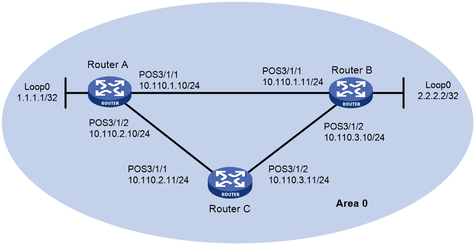
As shown in Figure 1, connect Router A, Router B, and Router C with each other through POS interfaces that use PPP encapsulation. Run OSPF on the routers to implement Layer 3 connectivity. Configure the POS interfaces to meet the following requirements:
· When the link between Router A and Router B is up, the traffic from Router A to Router B is forwarded through the path Router A > Router B.
· Upon receiving MS-RDI signals from Router B, Router A does not immediately shut down POS 3/1/1. Instead, Router A places the POS interface in down state if the signals keeps arriving within 100 milliseconds.
· When POS 3/1/1 on Router A goes down, the traffic from Router A to Router B switches to the path Router A > Router C > Router B.
Analysis
To configure Router A to take an action when an RDI alarm occurs on a POS interface, use the alarm-detect rdi action link-down command.
To configure Router A to place a Pos interface in down state only if DRI alarms keeps occurring on the interface within a period of time, set the physical state change suppression interval.
Restrictions and guidelines
When two routers are directly connected through POS interfaces, set different clock modes on the two routers.
Procedures
Configuring Router A
1. Configure interfaces:
# Assign an IP address to POS 3/1/1.
<RouterA> system-view
[RouterA] interface pos 3/1/1
[RouterA-Pos3/1/1] ip address 10.110.1.10 255.255.255.0
# Enable PPP encapsulation on POS 3/1/1.
[RouterA-Pos3/1/1] link-protocol ppp
# Set the clock mode to master for POS 3/1/1.
[RouterA-Pos3/1/1] clock master
# Configure POS 3/1/1 to go down when an RDI alarm occurs.
[RouterA-Pos3/1/1] alarm-detect rdi action link-down
# Set the physical state change suppression interval to 100 milliseconds for POS 3/1/1.
[RouterA-Pos3/1/1] link-delay msec 100
[RouterA-Pos3/1/1] quit
# Assign an IP address to POS 3/1/2.
[RouterA] interface pos 3/1/2
# Enable PPP encapsulation on POS 3/1/2.
[RouterA-Pos3/1/2] ip address 10.110.2.10 255.255.255.0
[RouterA-Pos3/1/2] link-protocol ppp
# Set the clock mode to master for POS 3/1/2.
[RouterA-Pos3/1/2] clock master
[RouterA-Pos3/1/2] quit
2. Configure OSPF:
[RouterA] ospf
[RouterA-ospf-1] area 0
[RouterA-ospf-1-area-0.0.0.0] network 10.110.1.0 0.0.0.255
[RouterA-ospf-1-area-0.0.0.0] network 10.110.2.0 0.0.0.255
[RouterA-ospf-1-area-0.0.0.0] network 1.1.1.1 0.0.0.0
[RouterA-ospf-1-area-0.0.0.0] quit
[RouterA-ospf-1] quit
Configuring Router B
1. Configure interfaces:
# Assign an IP address to POS 3/1/1, and enable PPP encapsulation on the interface.
<RouterB> system-view
[RouterB] interface pos 3/1/1
[RouterB-Pos3/1/1] ip address 10.110.1.11 255.255.255.0
[RouterB-Pos3/1/1] link-protocol ppp
[RouterB-Pos3/1/1] quit
# Assign an IP address to POS 3/1/2, and enable PPP encapsulation on the interface.
[RouterB] interface pos 3/1/2
[RouterB-Pos3/1/2] ip address 10.110.3.10 255.255.255.0
[RouterB-Pos3/1/2] link-protocol ppp
[RouterB-Pos3/1/2] quit
2. Configure OSPF:
[RouterB] ospf
[RouterB-ospf-1] area 0
[RouterB-ospf-1-area-0.0.0.0] network 10.110.1.0 0.0.0.255
[RouterB-ospf-1-area-0.0.0.0] network 10.110.3.0 0.0.0.255
[RouterB-ospf-1-area-0.0.0.0] network 2.2.2.2 0.0.0.0
[RouterB-ospf-1-area-0.0.0.0] quit
[RouterB-ospf-1] quit
Configuring Router C
1. Configure interfaces:
# Assign an IP address to POS 3/1/1, and enable PPP encapsulation on the interface.
<RouterC> system-view
[RouterC] interface pos 3/1/1
[RouterC-Pos3/1/1] ip address 10.110.2.11 255.255.255.0
[RouterC-Pos3/1/1] link-protocol ppp
[RouterC-Pos3/1/1] quit
# Assign an IP address to POS 3/1/2, and enable PPP encapsulation on the interface.
[RouterC] interface pos 3/1/2
[RouterC-Pos3/1/2] ip address 10.110.3.11 255.255.255.0
[RouterC-Pos3/1/2] link-protocol ppp
# Set the clock mode to master for POS 3/1/2.
[RouterC-Pos3/1/2] clock master
[RouterC-Pos3/1/2] quit
2. Configure OSPF:
[RouterC] ospf
[RouterC-ospf-1] area 0
[RouterC-ospf-1-area-0.0.0.0] network 10.110.2.0 0.0.0.255
[RouterC-ospf-1-area-0.0.0.0] network 10.110.3.0 0.0.0.255
[RouterC-ospf-1-area-0.0.0.0] quit
[RouterC-ospf-1] quit
Verifying the configuration
# On Router A, display information about the routes to 2.2.2.2/32 (Router B).
<RouterA> display ip routing-table 2.2.2.2 verbose
Summary Count : 1
Destination: 2.2.2.2/32
Protocol: OSPF
Process ID: 1
SubProtID: 0x1 Age: 04h20m37s
FlushedAge: 15h28m49s
Cost: 1 Preference: 10
IpPre: N/A QosLocalID: N/A
Tag: 0 State: Active Adv
OrigTblID: 0x0 OrigVrf: default-vrf
TableID: 0x2 OrigAs: 0
NibID: 0x26000002 LastAs: 0
AttrID: 0xffffffff Neighbor: 0.0.0.0
Flags: 0x1008c OrigNextHop: 10.110.1.11
Label: NULL RealNextHop: 10.110.1.11
BkLabel: NULL BkNextHop: N/A
SRLabel: NULL Interface: Pos3/1/1
BkSRLabel: NULL BkInterface: N/A
Tunnel ID: Invalid IPInterface: Pos3/1/1
BkTunnel ID: Invalid BkIPInterface: N/A
InLabel: NULL ColorInterface: N/A
SIDIndex: NULL BkColorInterface: N/A
FtnIndex: 0x0 TunnelInterface: N/A
TrafficIndex: N/A BkTunnelInterface: N/A
Connector: N/A PathID: 0x0
UserID: 0x0 SRTunnelID: Invalid
SID Type: N/A NID: Invalid
FlushNID: Invalid BkNID: Invalid
BkFlushNID: Invalid StatFlags: 0x0
SID: N/A
BkSID: N/A
The output shows that the route between Router A and Router B is a direct route.
# Verify that POS 3/1/1 on Router A goes down after Router A keeps receiving RDI signals from Router B within 100 milliseconds.
<RouterA> display interface pos 3/1/1 brief
Brief information on interfaces in route mode:
Link: ADM - administratively down; Stby - standby
Protocol: (s) - spoofing
Interface Link Protocol Primary IP Description
Pos3/1/1 DOWN DOWN --
# Verify that the next hop of the route to 2.2.2.2/32 (Router B) on Router A becomes Router C.
<RouterA> display ip routing-table 2.2.2.2 verbose
Summary Count : 1
Destination: 2.2.2.2/32
Protocol: OSPF
Process ID: 1
SubProtID: 0x1 Age: 04h20m37s
FlushedAge: 15h28m49s
Cost: 2 Preference: 10
IpPre: N/A QosLocalID: N/A
Tag: 0 State: Active Adv
OrigTblID: 0x0 OrigVrf: default-vrf
TableID: 0x2 OrigAs: 0
NibID: 0x26000002 LastAs: 0
AttrID: 0xffffffff Neighbor: 0.0.0.0
Flags: 0x1008c OrigNextHop: 10.110.2.11
Label: NULL RealNextHop: 10.110.2.11
BkLabel: NULL BkNextHop: N/A
SRLabel: NULL Interface: Pos3/1/2
BkSRLabel: NULL BkInterface: N/A
Tunnel ID: Invalid IPInterface: Pos3/1/2
BkTunnel ID: Invalid BkIPInterface: N/A
InLabel: NULL ColorInterface: N/A
SIDIndex: NULL BkColorInterface: N/A
FtnIndex: 0x0 TunnelInterface: N/A
TrafficIndex: N/A BkTunnelInterface: N/A
Connector: N/A PathID: 0x0
UserID: 0x0 SRTunnelID: Invalid
SID Type: N/A NID: Invalid
FlushNID: Invalid BkNID: Invalid
BkFlushNID: Invalid StatFlags: 0x0
SID: N/A
BkSID: N/A
CommBlockLen: 0 Priority: Critical
Configuration files
· Router A:
interface Pos3/1/1
clock master
link-delay msec 100
alarm-detect rdi action link-down
ip address 10.110.1.10 255.255.255.0
#
interface Pos3/1/2
clock master
ip address 10.110.1.10 255.255.255.0
#
ospf 1
area 0.0.0.0
network 10.110.1.0 0.0.0.255
network 10.110.2.0 0.0.0.255
network 1.1.1.1 0.0.0.0
#
· Router B:
#
interface Pos3/1/1
ip address 10.110.1.11 255.255.255.0
#
interface Pos3/1/2
ip address 10.110.3.10 255.255.255.0
#
ospf 1
area 0.0.0.0
network 10.110.1.0 0.0.0.255
network 10.110.3.0 0.0.0.255
network 2.2.2.2 0.0.0.0
#
· Router C:
#
interface Pos3/1/1
ip address 10.110.1.10 255.255.255.0
#
interface Pos3/1/2
clock master
ip address 10.110.1.10 255.255.255.0
#
ospf 1
area 0.0.0.0
network 10.110.2.0 0.0.0.255
network 10.110.3.0 0.0.0.255
#
Example: Directly connecting routers through POS interfaces that use HDLC
Network configuration
As shown in Figure 2, configure an HDLC link bundle to increase bandwidth and enhance connection reliability between Router A and Router B.

Restrictions and guidelines
An interface can belong to only one HDLC link bundle at any point in time. To assign a member interface to another HDLC link bundle, remove the interface from the current HDLC link bundle first.
The link layer protocol of an interface to be assigned to an HDLC link bundle must be HDLC. After the interface is assigned to the HDLC link bundle, its link layer protocol cannot be changed.
When two routers are directly connected through POS interfaces, set different clock modes on the two routers.
Procedures
Configuring Router A
# Create HDLC link bundle interface 1 and assign an IP address to it.
<RouterA> system-view
[RouterA] interface hdlc-bundle 1
[RouterA-HDLC-bundle1] ip address 1.1.1.1 24
[RouterA-HDLC-bundle1] quit
# Set the clock mode to master for POS 3/1/1, and enable HDLC encapsulation on the interface.
[RouterA] interface pos 3/1/1
[RouterA-Pos3/1/1] clock master
[RouterA-Pos3/1/1] link-protocol hdlc
# Assign POS 3/1/1 to HDLC link bundle interface 1.
[RouterA-Pos3/1/1] bundle id 1
[RouterA-Pos3/1/1] quit
# Set the clock mode to master for POS 3/1/2, and enable HDLC encapsulation on the interface.
[RouterA] interface pos 3/1/2
[RouterA-Pos3/1/2] clock master
[RouterA-Pos3/1/2] link-protocol hdlc
# Assign POS 3/1/2 to HDLC link bundle interface 1.
[RouterA-Pos3/1/2] bundle id 1
[RouterA-Pos3/1/2] quit
Configuring Router B
# Create HDLC link bundle interface 1 and assign an IP address to it.
<RouterB> system-view
[RouterB] interface hdlc-bundle 1
[RouterB-HDLC-bundle1] ip address 1.1.1.2 24
[RouterB-HDLC-bundle1] quit
# Enable HDLC encapsulation on the interface.
[RouterB] interface pos 3/1/1
[RouterB-Pos3/1/1] link-protocol hdlc
# Assign POS 3/1/1 to HDLC link bundle interface 1.
[RouterB-Pos3/1/1] bundle id 1
[RouterB-Pos3/1/1] quit
# Enable HDLC encapsulation on the interface.
[RouterB] interface pos 3/1/2
[RouterB-Pos3/1/2] link-protocol hdlc
# Assign POS 3/1/2 to HDLC link bundle interface 1.
[RouterB-Pos3/1/2] bundle id 1
[RouterB-Pos3/1/2] quit
Verifying the configuration
# Verify that the bundle interfaces on Router A and Router B can ping each other.
[RouterA] ping –a 1.1.1.1 1.1.1.2
Ping 1.1.1.2 (1.1.1.2) from 1.1.1.1: 56 data bytes, press CTRL_C to break
56 bytes from 1.1.1.2: icmp_seq=0 ttl=255 time=0.000 ms
56 bytes from 1.1.1.2: icmp_seq=1 ttl=255 time=0.000 ms
56 bytes from 1.1.1.2: icmp_seq=2 ttl=255 time=0.000 ms
56 bytes from 1.1.1.2: icmp_seq=3 ttl=255 time=0.000 ms
56 bytes from 1.1.1.2: icmp_seq=4 ttl=255 time=0.000 ms
--- Ping statistics for 1.1.1.2 ---
5 packet(s) transmitted, 5 packet(s) received, 0.0% packet loss
round-trip min/avg/max/std-dev = 0.000/0.000/0.000/0.000 ms
# Display HDLC link bundle information on Router A and Router B. This example uses Router A.
[RouterA] display bundle hdlc-bundle 1 slot 3
Bundle: HDLC-bundle1
Selected members: 2, Total bandwidth: 1244160 kbps
Member State Bandwidth(kbps) Priority
Pos3/1/1 Selected 622080 32768
Pos3/1/2 Selected 622080 32768
The output shows that HDLC bundle 1 has member interfaces POS 3/1/1 and POS 3/1/2 and both of the member interfaces are in Selected state.
Configuration files
· Router A:
#
interface pos 3/1/1
clock master
link-protocol hdlc
bundle id 1
#
interface pos 3/1/2
clock master
link-protocol hdlc
bundle id 1
#
interface hdlc-bundle 1
ip address 1.1.1.1 24
#
· Router B:
#
interface pos 3/1/1
link-protocol hdlc
bundle id 1
#
interface pos 3/1/2
link-protocol hdlc
bundle id 1
#
interface hdlc-bundle 1
ip address 1.1.1.2 24
#
Related documentation
· H3C CR16000-F Routers Interface Configuration Guide-R8385P09
· H3C CR16000-F Routers Interface Command Reference-R8385P09
· H3C CR16000-F Routers Layer 2—WAN Access Configuration Guide-R8385P09
· H3C CR16000-F Routers Layer 2—WAN Access Command Reference-R8385P09
