- Table of Contents
-
- H3C Servers Storage Controller User Guide-6W107
- 00-Preface
- 01-Storage controller overview
- 02-Storage controller features
- 03-Configuring an embedded RSTe RAID controller
- 04-Configuring an NVMe VROC module
- 05-Configuring a P430 storage controller
- 06-Configuring a 1000 storage controller
- 07-Configuring a 9361, 9440, 9460, L460, P5408, or H5408 storage controller
- 08-Configuring an H460, P460, P240 or P4408 storage controller
- 09-Configuring a 9300 storage controller
- 10-Configuring a 9311 storage controller
- 11-Configuring an LSI 9400 or 9500 series storage controller
- 12-Configuring a RAID-MARVELL-SANTACRUZ-LP-2i storage controller
- 13-Appendix A Troubleshooting storage controllers
- 14-Appendix B RAID arrays and fault tolerance
- Related Documents
-
14-Appendix B RAID arrays and fault tolerance
Appendix B RAID arrays and fault tolerance
RAID arrays
Physical drives
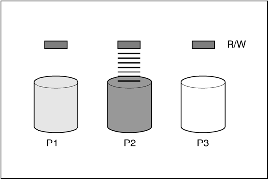
The capacity and performance of a single physical drive is adequate for home users. However, business users demand higher storage capacities, higher data transfer rates, and greater protection against data loss when drives fail.
As shown in Figure 1, connecting extra physical drives (denoted by Pn) to a system increases the total storage capacity, but has no effect on the efficiency of read/write (R/W) operations. Data can still be transferred to only one physical drive at a time.
Figure 1 Data can still be transferred to only one physical drive at a time
Logical drives
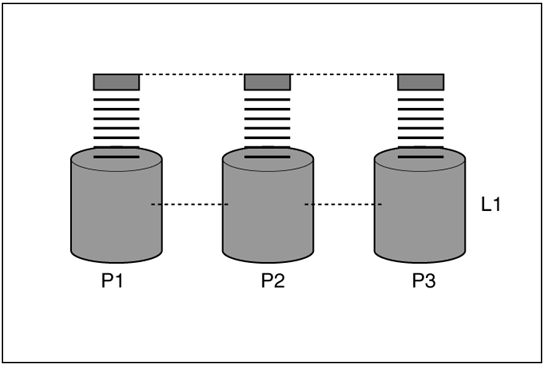
As shown in Figure 2, with a storage controller installed in the system, the capacity of several physical drives can be combined into one or more virtual units called logical drives (also called logical volumes and denoted by Ln). The read/write heads of all the constituent physical drives are active simultaneously, reducing the total time required for data transfer.
Figure 2 The read/write heads of all the constituent physical drives are active simultaneously
Data striping
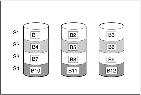
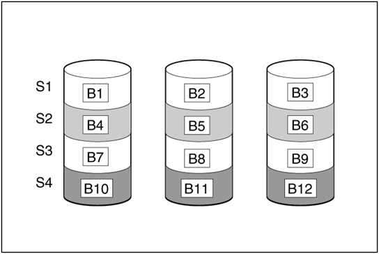
Data striping divides continuous data into parts of the same size and writes these parts into different drives. As shown in Figure 3, each unit of data is called a block (denoted by Bn), and adjacent blocks form a set of data stripes (Sn) across all the physical drives that comprise the logical drive.
Because the read/write heads are active simultaneously, the same amount of data is written to each drive during any given time interval.
Figure 3 Data blocks and stripes
For data in the logical drive to be readable, the data block sequence must be the same in every stripe. This sequencing process is performed by the storage controller, which sends the data blocks to the drive write heads in the correct order.
A natural consequence of the striping process is that each physical drive in a given logical drive contains the same amount of data. If one physical drive has a larger capacity than other physical drives in the same logical drive, the extra capacity is wasted because it cannot be used by the logical drive.
RAID arrays
As shown in Figure 4, a group of physical drives containing the logical drive is called a RAID array (or array, denoted by An). Since all the physical drives in an array are commonly configured into just one logical drive, the term logical drive is often used to refer to an array. However, an array can contain several logical drives, each of a different size.
Each logical drive in an array is distributed across all of the physical drives within the array. A logical drive can also extend across more than one port on the same controller, but it cannot extend across more than one controller.
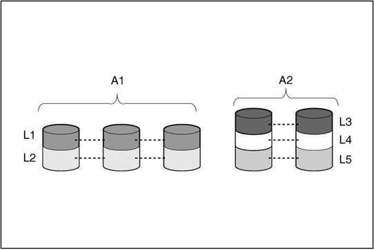
Drive failure, although rare, can be catastrophic. For arrays that are configured as shown in Figure 4, failure of any physical drive in the array causes every logical drive in the array to suffer irretrievable data loss. To avoid data loss due to physical drive failure, logical drives are configured with fault tolerance. For more information, see “Fault tolerance methods.”
For any configuration except RAID 0, further protection against data loss can be achieved by assigning a drive as an online spare (or hot spare). This drive contains no data and is connected to the same controller as the array. When any other physical drive in the array fails, the controller automatically rebuilds information that was originally on the failed drive to the online spare. The system is thus restored to full RAID-level data protection, although it now no longer has an online spare. (However, in the unlikely event that another drive in the array fails while data is being rewritten to the online spare, the logical drive will still fail.)
When you configure an online spare, it is automatically assigned to all logical drives in the same array. If several arrays are all on one controller, you do not need to assign a separate online spare to each array. Instead, you can configure one hard drive to be the online spare for the arrays.
Fault tolerance methods
RAID 0
RAID 0 does not support fault tolerance. As shown in Figure 5, RAID 0 configuration provides data striping, but there is no protection against data loss when a drive fails.
Application scenarios
RAID 0 is useful for rapid storage of large amounts of noncritical data (for printing or image editing, for example) or when cost is the most important consideration.
Advantages
· Has the highest write performance among all RAID methods.
· Has the lowest cost per unit of stored data among all RAID methods.
· All drive capacity is used to store data (none needed for fault tolerance).
Disadvantages
· All data on the logical drive is lost if a physical drive fails.
· Cannot use an online spare.
· Can only preserve data by backing it up to external drives.
RAID 1
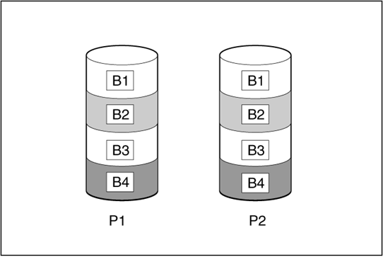
RAID 1 is also called drive mirroring. As shown in Figure 6, P1 and P2 represent two physical drives, and they form a logical drive. Each data block is duplicated to a second drive and saved on two drives.
Application scenarios
RAID 1 is useful when high performance and data protection are more important than the cost of physical drives.
Advantages
· Has the highest security performance among all RAID methods.
· No data is lost as long as no failed drive is mirrored to another failed drive.
· Up to half of the physical drives in the array can fail.
Disadvantages
· This method is expensive as it needs many drives for fault tolerance.
· Only half of the total drive capacity is usable for data storage.
RAID 1E
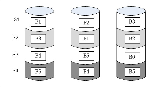
RAID 1E enhances RAID 1. RAID 1E not only mirrors data but also stripes data. RAID 1E can mirror data for an odd number of drives, as shown in Figure 7.
Application scenarios
RAID 1E is useful when high performance and data protection are more important than the cost of physical drives.
Advantages
· Has higher read performance than RAID 1 and mirrors data for an odd number of drives.
· No data is lost as long as no failed drive is mirrored to another failed drive.
· Up to half of the physical drives in the array can fail.
Disadvantages
· This method is expensive as it needs many drives for fault tolerance.
· Only half of the total drive capacity is usable for data storage.
· Has lower security performance than RAID 10 when the same even number of drives are used to create the array.
RAID 5
As shown in Figure 8, in RAID 5 configuration, data protection is provided by parity data (denoted by Px,y). This parity data is calculated stripe by stripe from the user data that is written to all other blocks within that stripe. The blocks of parity data are distributed evenly over every physical drive within the logical drive.
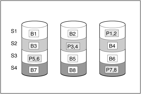
When a physical drive fails, data that was on the failed drive can be calculated from the remaining parity data and user data on the other drives in the array. This recovered data is usually written to an online spare in a process called a rebuild.
Application scenarios
RAID 5 is useful when cost, performance, and data availability are equally important.
Advantages
· Has high read performance.
· Data is not lost if only one physical drive fails.
· More drive capacity is usable than with RAID 10, because parity information requires only the storage space equivalent to one physical drive.
Disadvantages
· Has relatively low write performance.
· Data is lost if a second drive fails before data from the first failed drive is rebuilt.
RAID 6
As shown in Figure 9, RAID 6, like RAID 5, generates and stores parity information to protect against data loss caused by drive failure. However, RAID 6 uses two different sets of parity data (denoted by Px,y and Qx,y), allowing data to still be preserved if two drives fail. Each set of parity data uses a capacity equivalent to that of one of the constituent drives.
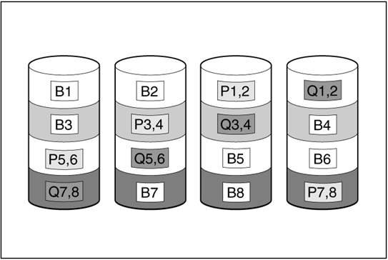
Application scenarios
RAID 6 is most useful when data loss is unacceptable, but cost is also an important factor. Data loss is less likely to occur in an array configured with RAID 6 than an array configured with RAID 5.
Advantages
· Has a high read performance.
· Has high data availability because any two drives can fail without loss of critical data.
· More drive capacity is usable than with RAID 10 because parity information requires only the storage space equivalent to two physical drives.
Disadvantages
The main disadvantage of RAID 6 is a relatively low write performance (lower than RAID 5), because of the need for two sets of parity data.
RAID 10
As shown in Figure 10, RAID 10 is a nested RAID level combining RAID 1 and RAID 0. To configure RAID 10, first configure RAID 1 and then RAID 0.
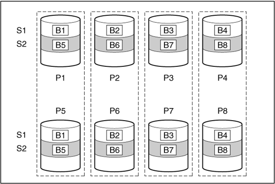
In each mirrored pair, the physical drive that is not busy answering other requests answers any read requests that are sent to the array. This behavior is called load balancing. If a physical drive fails, the remaining drive in the mirrored pair can still provide all the necessary data. Several drives in the array can fail without incurring data loss, as long as no two failed drives belong to the same mirrored pair.
Application scenarios
RAID 10 is useful when high performance and data protection are more important than the cost of physical drives.
Advantages
· Has the second highest read performance among all RAID methods.
· No data is lost as long as no failed drive is mirrored to another failed drive.
· Up to half of the physical drives in the array can fail.
Disadvantages
· This method is expensive as it needs many drives for fault tolerance.
· Only half of the total drive capacity is usable for data storage.
RAID 50
As shown in Figure 11, RAID 50 is a nested RAID level combining RAID 5 and RAID 0. The member drives are organized into several same RAID 5 logical drive groups (parity groups). RAID 50 configuration needs a minimum of six drives, which can be organized into two parity groups, each containing three drives.
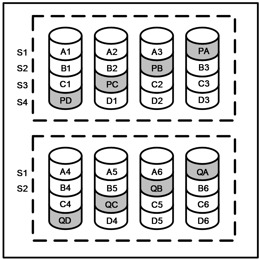
For any given number of drives, when the most parity groups are configured, the data loss probability is the lowest. For example, if 12 drives are used, configuring four parity groups is more secure than three parity groups. However, the more parity groups are configured, the less data can be stored on the array.
Application scenarios
RAID 50 is useful in large-sized databases, file servers, and application servers.
Advantages
· Has higher performance (especially write performance) than RAID 5.
· Has higher fault tolerance performance than RAID 0 and RAID 5.
· No data is lost even up to n (the number of parity groups) physical drives fail as long as the failed drives are in different parity groups.
Disadvantages
· Data is lost if a second drive in a parity group fails before data from the first failed drive in the parity group is rebuilt.
· More drive capacity is used for saving redundant or parity data than non-nested RAID levels.
RAID 60
As shown in Figure 12, RAID 60 is a nested RAID level combining RAID 6 and RAID 0. Member drives are organized into several same RAID 6 logical drive groups (parity groups). RAID 60 configuration needs a minimum of eight drives, which can be organized into two parity groups, each containing four drives.
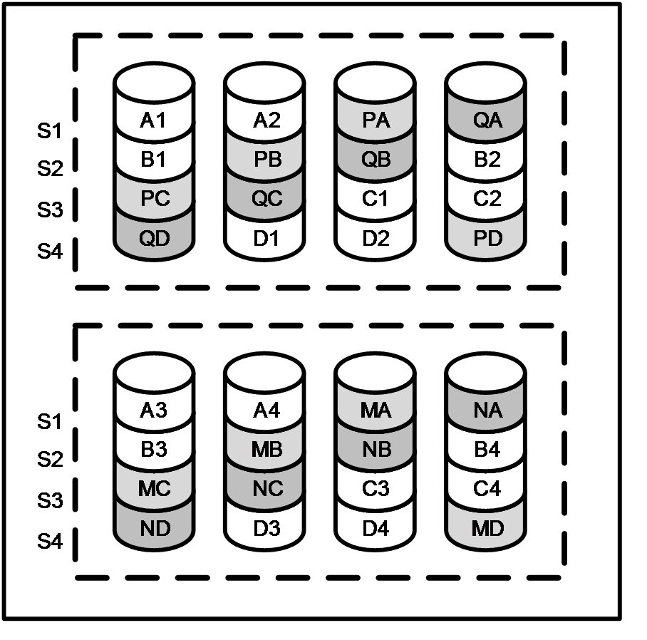
For any given number of drives, when the most parity groups are configured, the data loss probability is the lowest. For example, if 20 drives are used, configuring five parity groups is more secure than four parity groups. However, the more parity groups are configured, the less data can be stored on the array.
Application scenarios
RAID 60 is useful in archiving databases and high-availability solutions.
Advantages
· Has higher performance (especially write performance) than RAID 6.
· Has higher fault tolerance performance than RAID 0 and RAID 6.
· No data is lost even up to 2n (n is the number of parity groups) physical drives fail as long as no more than two drives fail in a parity group.
Disadvantages
· Data is lost if a third drive in a parity group fails before data from one of the two failed drives in the parity group is rebuilt.
· More drive capacity is used for saving redundant or parity data than non-nested RAID levels.
Probability of logical drive failure
The probability that a logical drive will fail depends on the RAID level setting and on the number and type of physical drives in the array. If the logical drive does not have an online spare, the following rules apply:
· A RAID 0 logical drive fails if one or more physical drives fail.
· A RAID 1, RAID 1E, or RAID 10 drive fails if any two failed physical drives are mirrored to each other.
¡ The maximum number of physical drives that can fail without causing failure of the logical drive is n/2, where n is the number of drives in the array. In practice, a logical drive usually fails before this maximum is reached. As the number of failed physical drives increases, it becomes increasingly likely that the newly failed drive is mirrored to a previously failed drive.
¡ The minimum number of physical drive failures that can cause the logical drive to fail is two. This situation occurs when the two failed drives are mirrored to each other. As the total number of drives in the array increases, the probability that the only two failed drives in an array are mirrored to each other decreases.
· A RAID 5 logical drive fails if two or more physical drives fail.
· A RAID 50 logical drive fails when two or more drives in a RAID 5 logical drive fail.
· A RAID 6 logical drive fails when three or more physical drives fail.
· A RAID 60 logical drive fails when three or more devices in a RAID 6 logical drive fail.
Selecting a RAID level
Follow the rules in Table 1 to select a RAID level.
Table 1 RAID level selection rules
|
Most important factor |
Important factor |
Suggested RAID levels |
|
Fault tolerance |
Cost |
RAID 6 |
|
I/O performance |
RAID 1E, RAID 10, RAID 50, RAID 60 |
|
|
Cost |
Fault tolerance |
RAID 6 |
|
I/O performance |
RAID 5 (RAID 0 if fault tolerance is not needed) |
|
|
I/O performance |
Cost |
RAID 5 (RAID 0 if fault tolerance is not needed) |
|
Fault tolerance |
RAID 1E, RAID 10, RAID 50, RAID 60 |
