- Table of Contents
-
- H3C Servers Storage Controller User Guide-6W107
- 00-Preface
- 01-Storage controller overview
- 02-Storage controller features
- 03-Configuring an embedded RSTe RAID controller
- 04-Configuring an NVMe VROC module
- 05-Configuring a P430 storage controller
- 06-Configuring a 1000 storage controller
- 07-Configuring a 9361, 9440, 9460, L460, P5408, or H5408 storage controller
- 08-Configuring an H460, P460, P240 or P4408 storage controller
- 09-Configuring a 9300 storage controller
- 10-Configuring a 9311 storage controller
- 11-Configuring an LSI 9400 or 9500 series storage controller
- 12-Configuring a RAID-MARVELL-SANTACRUZ-LP-2i storage controller
- 13-Appendix A Troubleshooting storage controllers
- 14-Appendix B RAID arrays and fault tolerance
- Related Documents
-
05-Configuring a P430 storage controller
Configuring a RAID-P430-M1 or RAID-P430-M2 storage controller
About RAID-P430-M1 and RAID-P430-M2 storage controllers
The RAID-P430-M1 and RAID-P430-M2 storage controllers support 6-Gbps and 12-Gbps SAS/SATA data channels and caching, which greatly increases performance and data security. For more information about storage controller details and the supported cache, contact Technical Support.
Features
Operating modes
The storage controller supports the following operating modes:
· RAID: expose raw mode—This is the default mode. In this mode, the system can identify and assign drive letters to both raw drives and member drives of RAID arrays.
· RAID: hide raw mode—In this mode, the system can identify and assign drive letters only to member drives of RAID arrays. Raw drives cannot be identified or used by the operating system.
· HBA mode—In this mode, physical drives are exposed as raw drives and RAID functions are disabled.
· Auto Volume mode—In this mode, physical drives with system partitions are exposed as raw drives. Physical drives without system partitions are configured as simple volumes.
· Simple Volume mode—In this mode, only non-redundant RAID arrays with the simple volume level (each contains only one drive) can be created. RAID arrays with other RAID levels cannot be created.
|
|
NOTE: Raw drives refer to drives that do not have RAID configuration. |
Before you configure RAID in RAID: expose raw or RAID: hide raw mode or set the controller operating mode to auto volume or simple volume mode, you must initialize target drives.
Before you configure the controller to operate in RAID: expose raw mode without RAID configuration or in HBA mode, you must uninitialize target drives.
For the new mode to take effect, restart the server after an operating mode change.
The operating system might fail to start up after the operating mode of the storage controller is changed. To resolve the issue, you can re-install the operating system. If the issue persists, contact Technical Support.
RAID levels
The supported RAID levels vary by storage controller model. For more information about the supported RAID levels of each storage controller, see H3C Servers Storage Controllers Technical Specifications.
Table 1 shows the minimum number of drives required by each RAID level and the maximum number of failed drives supported by each RAID level. For more information about RAID levels, see "Appendix B RAID arrays and fault tolerance."
Table 1 RAID levels and the numbers of drives for each RAID level
|
RAID level |
Min. drives required |
Max. failed drives |
|
RAID 0 |
2 |
0 |
|
RAID 1 |
2 |
1 |
|
RAID 1E |
3 |
Integer part of n/2, where n is the number of drives in the RAID 1E array. |
|
RAID 5 |
3 |
1 |
|
RAID 6 |
4 |
2 |
|
RAID 10 |
4 |
n, where n is the number of RAID 1 arrays in the RAID 10 array. |
|
RAID 50 |
6 |
n, where n is the number of RAID 5 arrays in the RAID 50 array. |
|
RAID 60 |
8 |
2n, where n is the number of RAID 6 arrays in the RAID 60 array. |
|
Simple Volume |
1 |
0 |
Hot spare drives
You can configure hot spare drives to improve data security. A hot spare drive is a standby drive that does not store any data. When a drive in a redundant RAID fails, a spare drive automatically replaces the failed drive and rebuilds the data of the failed drive.
The storage controller supports the following types of hot spare drives. For more information about hot spare drive types, see "Storage controller features."
· Global spare drive.
· Dedicated spare drive.
· Pooled spare drive.
Restrictions and guidelines for configuring RAID
· As a best practice, configure RAID with drives that do not contain RAID information.
· To build a RAID successfully and ensure RAID performance, make sure all drives in the RAID are the same type (HDDs or SSDs) and have the same connector type (SAS or SATA).
· For efficient use of storage, use drives that have the same capacity to build a RAID. If the drives have different capacities, the lowest capacity is used across all drives in the RAID.
· If you use one physical drive to create multiple RAIDs, RAID performance might decrease in addition to increased maintenance complexities.
High speed read/write cache
For the RAID-P430-M1 and RAID-P430-M2 storage controllers, you can enable caching on the storage controller by using ARCCONF commands. For more information, contact Technical Support.
Configuring RAID arrays in UEFI mode
This section describes how to configure RAID arrays through a storage controller in UEFI mode. For more information about how to enter the BIOS and set the boot mode to UEFI, see the BIOS user guide for the server.
RAID array configuration tasks at a glance
To configure RAID arrays in UEFI mode, perform the following tasks:
· Accessing the storage controller configuration screen
· Switching the storage controller operating mode
· (Optional.) Configuring hot spare drives
· (Optional.) Deleting RAID arrays
· (Optional.) Uninitializing drives
· (Optional.) Locating drives
· (Optional.) Erasing drives
· (Optional.) Restoring the default configuration for a storage controller
· (Optional.) Upgrading the storage controller firmware online
· (Optional.) Enabling RAID rebuilding
· (Optional.) Migrating RAID levels
· (Optional.) Expanding RAID capacity
Accessing the storage controller configuration screen
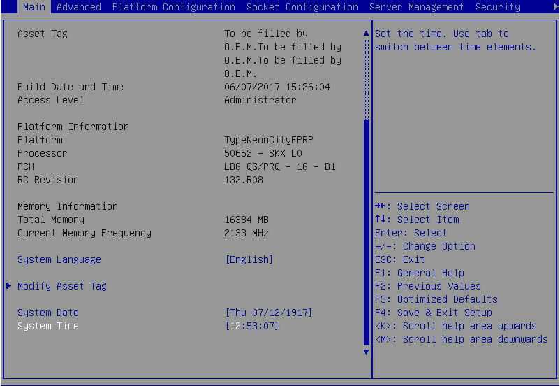
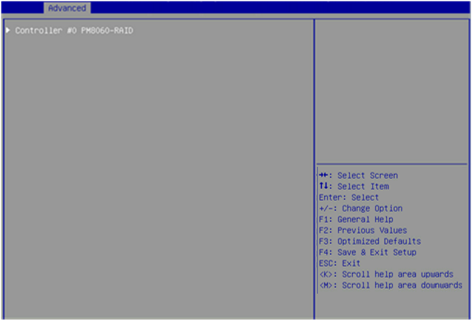
1. During server POST, press Delete, Esc, or F2 as prompted to open the BIOS setup screen as shown in Figure 1.
For how to navigate screens and modify settings, see the operation instructions at the lower right corner.
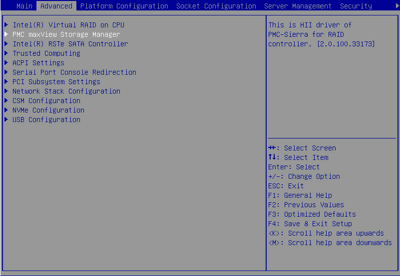
2. On the screen as shown in Figure 2, select Advanced > PMC maxView Storage Manager, and press Enter.
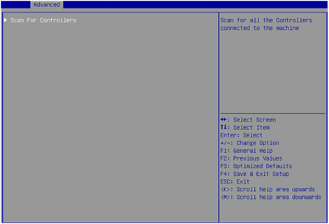
3. On the screen as shown in Figure 3, select Scan For Controllers, and press Enter.
Figure 3 Selecting Scan For Controllers
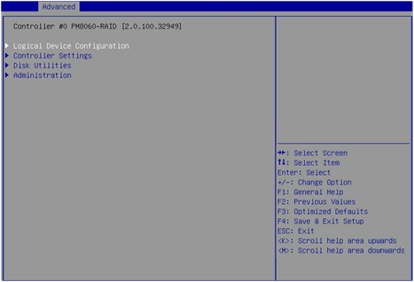
4. On the screen as shown in Figure 4, select Controller #0 PM8060-RAID, and press Enter.
Figure 4 Selecting Controller #0 PM8060-RAID
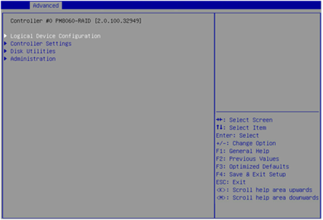
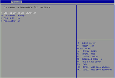
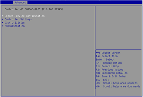
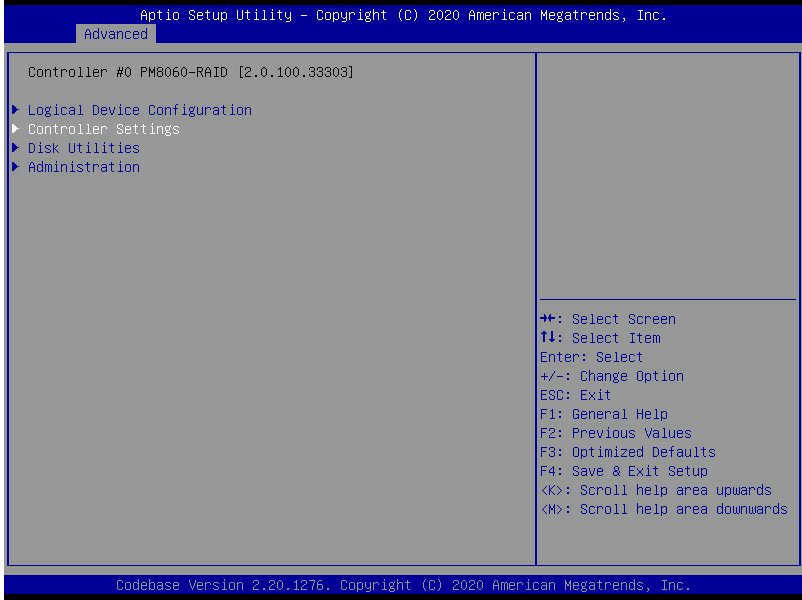
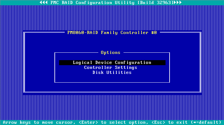
5. The storage controller configuration screen as shown in Figure 5 opens. This screen contains tasks as described in Table 2.
Figure 5 Storage controller configuration screen
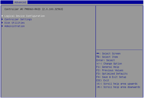
Table 2 Storage controller configuration tasks
|
Option |
Description |
|
Logical Device Configuration |
Select Logical Device Configuration to perform the following tasks: · Manage RAID arrays. · Create RAID arrays. · Initialize drives. · Erase drives. · Configure global hot spare drives. |
|
Controller Settings |
Select Controller Settings to perform the following tasks: · Modify the storage controller operating mode. · View the storage controller configuration information. · Restore the default configuration for a storage controller. |
|
Disk Utilities |
Select Disk Utilities to perform the following tasks: · View physical drive information. · Locate physical drives. · Format drives. |
|
Administration |
Select Administration to update the storage controller firmware. |
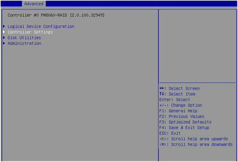
Switching the storage controller operating mode
1. On the storage controller configuration screen as shown in Figure 6, select Controller Settings, and press Enter.
Figure 6 Storage controller configuration screen
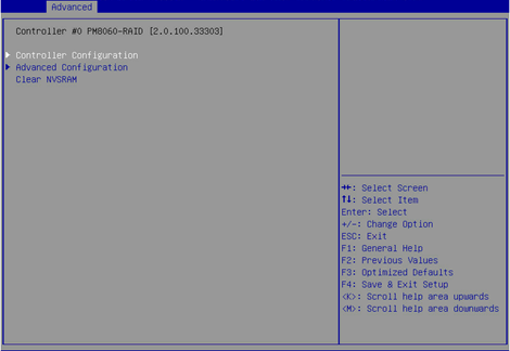
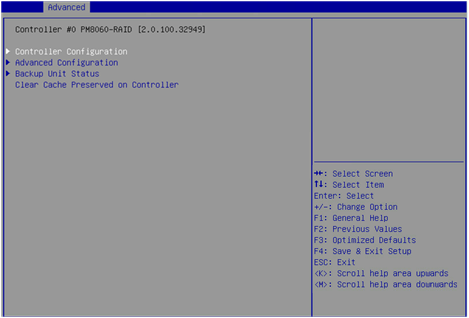
2. On the screen as shown in Figure 7, select Controller Configuration, and press Enter.
Figure 7 Controller Settings screen
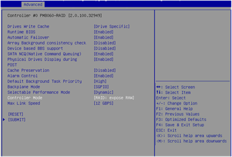
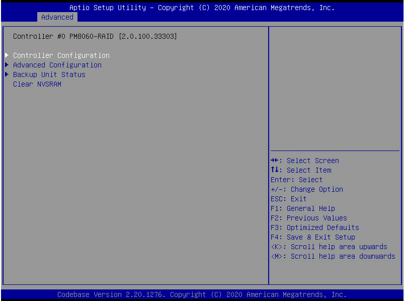
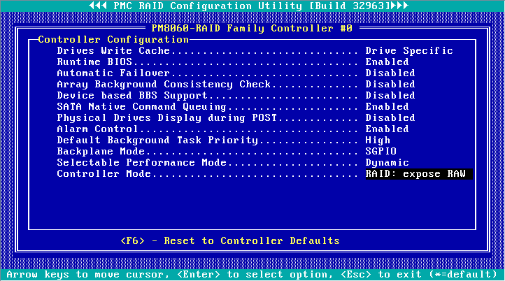
3. On the screen as shown in Figure 8, select Controller Mode, and press Enter.
Figure 8 Controller Configuration screen
4. On the screen as shown in Figure 9, select a storage controller operating mode, and press Enter.
Table 3 describes the storage controller operating modes.
Figure 9 Selecting a storage controller operating mode
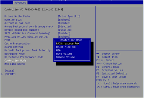
Table 3 Storage controller operating modes
|
Operating mode |
Description |
|
RAID: expose RAW |
All RAID functions can be used. Raw physical drives are exposed to the system. |
|
RAID: hide RAW |
All RAID functions can be used. Raw physical drives are not exposed to the system. |
|
HBA |
RAID functions are disabled. Raw physical drives are exposed to the system. Before setting this mode, you must delete all RAID arrays and hot spare drives, and perform the Uninitializing drives operation for all drives. |
|
Auto Volume |
In this mode, raw physical drives with system partitions are exposed to the system, and physical drives without system partitions are configured as simple volumes. Before setting this mode, you must delete all RAID arrays and hot spare drives in the system. |
|
Simple Volume |
In this mode, only non-redundant RAID arrays with the simple volume level (each contains only one drive) can be created. RAID arrays with other RAID levels cannot be created. Before setting this mode, you must delete all RAID arrays and hot spare drives in the system. |
Scanning drives
The storage controller might fail to timely recognize drives after the drives are hot swapped. To solve this problem, you can scan drives.
To scan drives:
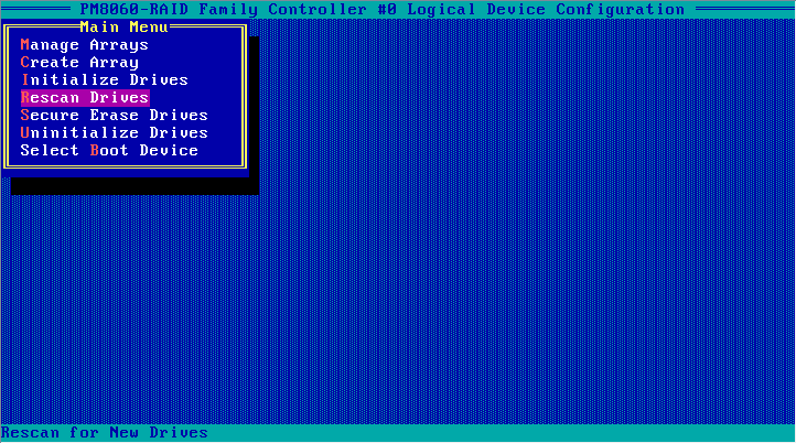
1. On the storage controller configuration screen as shown in Figure 10, select Logical Device Configuration, and press Enter.
Figure 10 Storage controller configuration screen
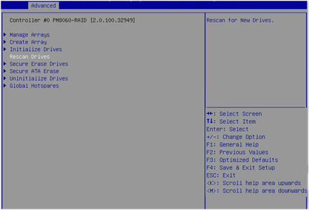
2. On the screen as shown in Figure 11, select Rescan Drives, and press Enter to scan drives.
Figure 11 Logical Device Configuration screen
Initializing drives
Initializing a drive is to divide a small partition from the drive for saving the RAID information. A raw drive must be initialized before it can be used for creating a RAID array or configured as a hot spare drive.
To initialize drives:
1. On the storage controller configuration screen as shown in Figure 12, select Logical Device Configuration, and press Enter.
Figure 12 Storage controller configuration screen

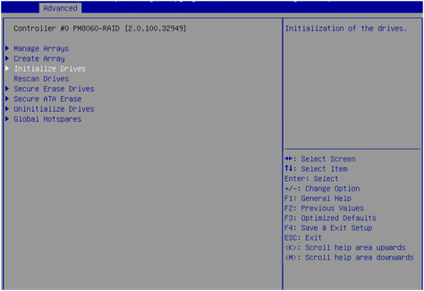
2. On the screen as shown in Figure 13, select Initialize Drives, and press Enter.
Figure 13 Logical Device Configuration screen
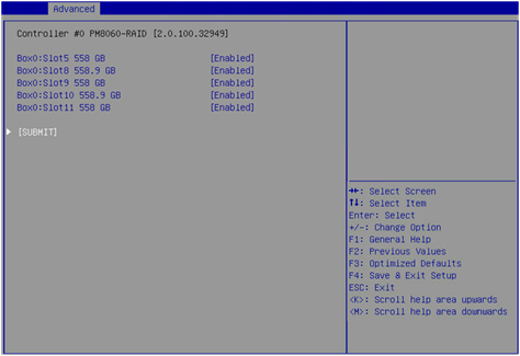
3. On the screen as shown in Figure 14, select the drives to be initialized. ([Enabled] following a drive means that the drive has been selected.) Then, select SUBMIT and press Enter.
4. If the system prompts that the initiation will erase all array information from the selected drives and affect RAID arrays using these selected drives, perform one of the following tasks:
¡ To verify if the drives are correctly selected, press ESC to go back to the previous step.
¡ If you have selected correct drives, select SUBMIT and then press Enter.
Figure 15 Drive initiation risk warning screen
Configuring RAID arrays
1. On the storage controller configuration screen as shown in Figure 16, select Logical Device Configuration, and press Enter.
Figure 16 Storage controller configuration screen
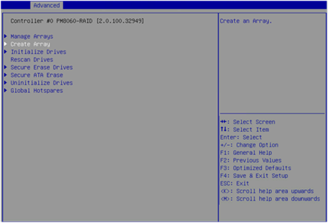
2. On the screen as shown in Figure 17, select Create Array, and press Enter.
Figure 17 Logical Device Configuration screen
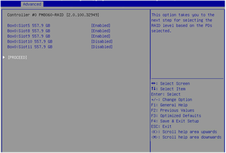
3. On the screen as shown in Figure 18, select the drives to be configured as a RAID array. ([Enabled] following a drive means that the drive has been selected.) Then, select PROCEED and press Enter.
A raw drive cannot be selected. To configure a RAID array for the drive, you must first initialize the drive. For more information about initializing drives, see "Initializing drives."
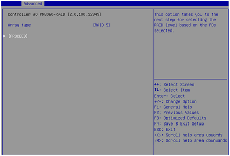
4. On the screen as shown in Figure 19, select Array type to set a RAID level, select PROCEED, and press Enter.
Figure 19 Selecting a RAID level
5. On the screen as shown in Figure 20, set the Array Label, Stripe Size, Array Size, Array Size Selection, Read Cache, Write Cache, and Create RAID via parameters, select SUBMIT, and press Enter to create the array.
Table 4 describes the configuration parameters.
Figure 20 Setting RAID parameters
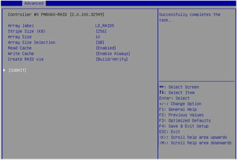
Table 4 Configuration parameters
|
Parameter |
Description |
|
Array Label |
RAID array name. The default is DefaultValue0. |
|
Stripe Size |
Strip size, which determines the data block size of a stripe on each drive. |
|
Array Size Selection |
RAID array capacity. |
|
Read Cache |
Read cache policy status. Options are Enabled and Disabled. |
|
Write Cache |
Write cache policy status: · Enable Always—Always enables the write cache. Without a supercapacitor installed, this status might cause data loss if power supply fails. · Enable With Backup Unit—Disables the write cache when the supercapacitor is absent or not ready. · Disabled—Disables the write cache. |
|
Create RAID via |
Operation after the RAID array is created. Options are as follows: · Quick Init—Performs initialization only when the corresponding stripe is accessed after the RAID array is created. · Skip Init—Establishes the RAID relationship immediately after the RAID array is created without clearing the data. · Build/Verify—Verifies the data for the drives after the RAID array is created to make the drives comply with the RAID level. · Clear—Clears the data of drives after the RAID array is created, which takes a long time. |
|
|
NOTE: If Build/Verify is selected, the read/write performance of a drive is low when the data of the drive is being verified. Do not perform any other tasks until the drive status becomes Optimal. |
6. On the storage controller configuration screen, select Logical Device Configuration > Manage Arrays, and press Enter, as shown in Figure 21.
Figure 21 Logical Device Configuration screen
7. On the screen as shown in Figure 22, the created RAID array is displayed. Select the RAID array, and press Enter.
Figure 22 Manage Arrays screen
8. On the RAID management screen that opens, select Array Properties, and press Enter to view detailed information about the RAID array (including the RAID array name, RAID level, and member drives), as shown in Figure 23.
Figure 23 RAID array information screen
Configuring hot spare drives
After configuring a RAID array, you can configure hot spare drives for the RAID array to improve the data security. You can configure global or dedicated hot spare drives as needed.
Configuring global hot spare drives
1. On the storage controller configuration screen as shown in Figure 24, select Logical Device Configuration, and press Enter.
Figure 24 Storage controller configuration screen

2. On the screen as shown in Figure 25, select Global Hotspares, and press Enter.
Figure 25 Logical Device Configuration screen
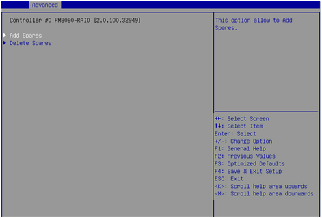
3. On the screen as shown in Figure 26, select Add Spares, and press Enter.
Figure 26 Global Hotspares configuration screen
|
|
NOTE: To delete a host spare drive, select Delete Spares on the screen as shown in Figure 26. |
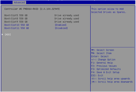
4. On the screen as shown in Figure 27, select the drives to be configured as global hot spare drives. ([Enabled] following a drive means that the drive has been selected.) Then, select ADD, and press Enter to configure the global hot spare drives.
|
|
NOTE: To configure a raw drive as a hot spare drive, you must first initialize the drive. For how to initialize drives, see "Initializing drives." |
Configuring dedicated hot spare drives
1. On the storage controller configuration screen, select Logical Device Configuration > Manage Arrays, and press Enter.
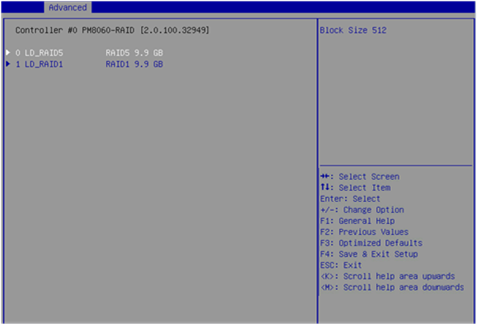
2. On the screen as shown in Figure 28, select the RAID array for which you want to configure dedicated hot spare drives, and press Enter.
Figure 28 Selecting a RAID array
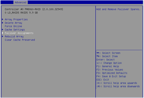
3. On the screen as shown in Figure 29, select Failover Assignments, and press Enter.
Figure 29 Selecting Failover Assignments
4. On the screen as shown in Figure 30, select Add Spares, and press Enter.
Figure 30 Failover Assignments

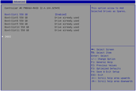
5. On the screen as shown in Figure 31, select the drives to be configured as dedicated hot spare drives. ([Enabled] following a drive means that the drive has been selected.) Then, select ADD, and press Enter to configure the dedicated hot spare drives.
Deleting RAID arrays
1. On the storage controller configuration screen as shown in Figure 32, select Logical Device Configuration, and press Enter.
Figure 32 Storage controller configuration screen

2. On the screen as shown in Figure 33, select Manage Arrays, and press Enter.
Figure 33 Logical Device Configuration screen

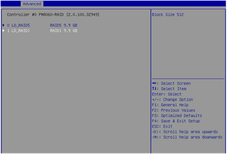
3. On the screen as shown in Figure 34, select the RAID array to be deleted, and press Enter.
Figure 34 Selecting the RAID array to be deleted
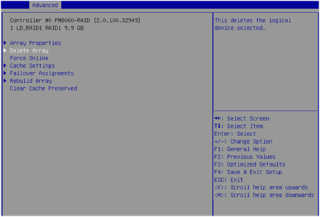
4. On the screen as shown in Figure 35, select Delete Array, and press Enter.
Figure 35 Selecting Delete Array
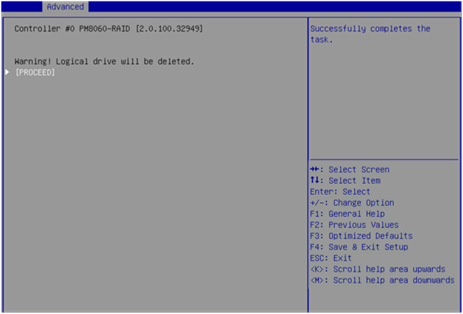
5. On the screen as shown in Figure 36, select PROCEED or SUBMIT, and press Enter to delete the selected RAID array.
Figure 36 Deleting a RAID array
Uninitializing drives
Perform this task to clear data, Adaptec metadata, and reserved space on drives, and remove the system partitions. After a drive in Ready state is uninitialized, it returns to the raw state.
To uninitialize drives:
1. On the storage controller configuration screen as shown in Figure 37, select Logical Device Configuration, and press Enter.
Figure 37 Storage controller configuration screen
2. On the screen as shown in Figure 38, select Uninitialize Drives, and press Enter.
Figure 38 Logical Device Configuration screen
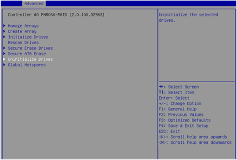
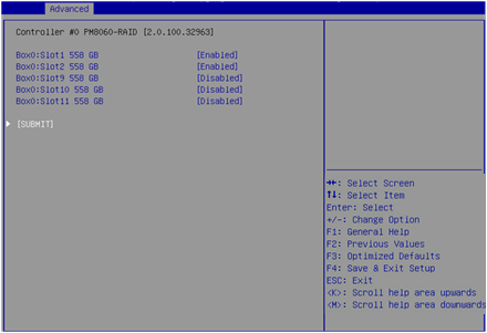
3. On the screen as shown in Figure 39, select the drives to be uninitialized. ([Enabled] following a drive means the drive has been selected.) Then, select SUBMIT, and press Enter to uninitialize the drives.
Locating drives
1. On the storage controller configuration screen as shown in Figure 40, select Disk Utilities, and press Enter.
Figure 40 Storage controller configuration screen
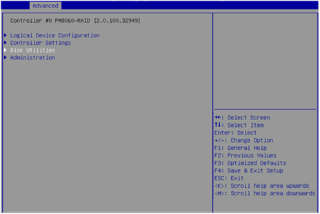
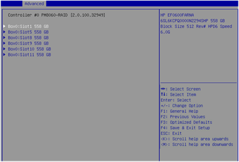
2. On the screen as shown in Figure 41, select the drive to be operated, and press Enter.
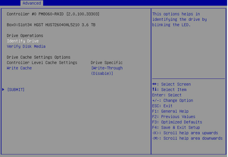
3. On the screen as shown in Figure 42, select an operation (Identify Drive in this example), and press Enter.
Table 5 describes the operation options.
Figure 42 Drive information display/operation screen
|
Option |
Description |
|
Verify Disk Media |
Verify the media of the drive. |
|
Identify Drive |
Locate the drive. With this operation performed for a drive, the Fault/UID LED on the drive backplane turns steady blue. |
|
Write Cache |
Set the write cache for the drive. |
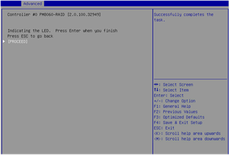
4. On the screen as shown in Figure 43, select PROCEED, and press Enter.
Then, the Fault/UID LED on the drive turns steady blue.
Erasing drives
|
|
WARNING! · To avoid data loss, do not enter the operating system and read or write the drives during the drive erasing process. · To avoid drive failure, do not perform any other operations during the drive erasing process. |
To erase drives:
1. On the storage controller configuration screen as shown in Figure 44, select Logical Device Configuration, and press Enter.
Figure 44 Storage controller configuration screen
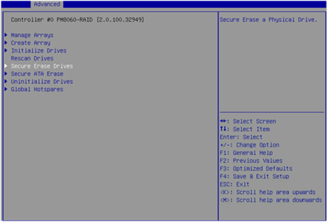
2. On the screen as shown in Figure 45, select Secure Erase Drives, and press Enter.
Figure 45 Selecting Secure Erase Drives
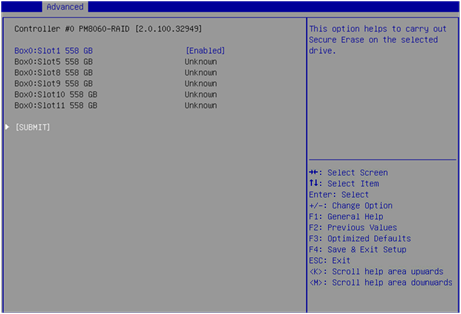
3. On the screen as shown in Figure 46, select the drives to be erased. ([Enabled] following a drive means that the drive has been selected.) Then, select SUBMIT, and press Enter.
Figure 46 Selecting the drives to be erased
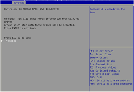
4. On the screen as shown in Figure 47, select PROCEED or SUBMIT, and press Enter to erase the drives.
Restoring the default configuration for a storage controller
1. On the storage controller configuration screen as shown in Figure 48, select Controller Settings, and press Enter.
Figure 48 Storage controller configuration screen

2. On the screen as shown in Figure 49, select Controller Configuration, and press Enter.
Figure 49 Controller Settings screen
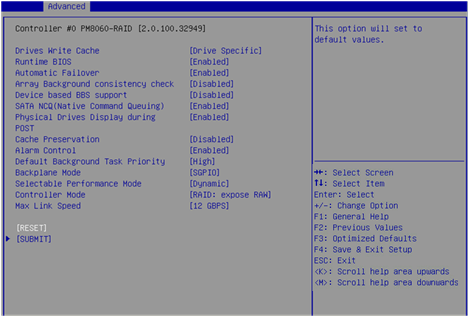
3. On the screen as shown in Figure 50, you can view the basic configuration of the storage controller. Select RESET, and press Enter.
|
|
IMPORTANT: The backplane mode sets the LED lighting policy. After the storage controller configuration is restored to the default, the LED lighting policy becomes IBPI, which causes the LED to operate abnormally. You must set the LED lighting policy to SGPIO. |
Figure 50 Controller Configuration screen
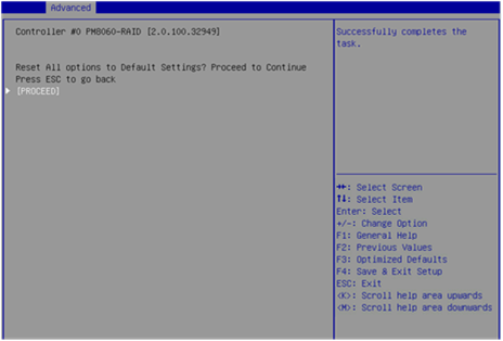
4. On the screen as shown in Figure 51, select PROCEED or SUBMIT, and press Enter to restore the storage controller configuration to the default.
Figure 51 Restoring the storage controller configuration to the default
Upgrading the storage controller firmware online
1. On the storage controller configuration screen as shown in Figure 52, select Administration, and press Enter.
Figure 52 Storage controller configuration screen
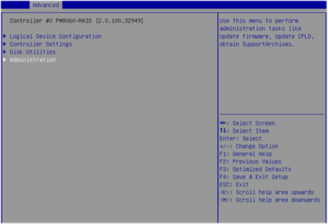
2. On the screen as shown in Figure 53, select FW update from Media, and press Enter.
Figure 53 Administration screen
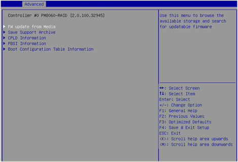
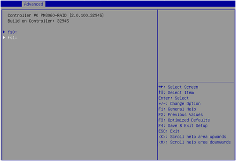
3. On the screen as shown in Figure 54, select the device where the update file resides (fs1 in this example), and press Enter.
Figure 54 Selecting the device where the update file resides
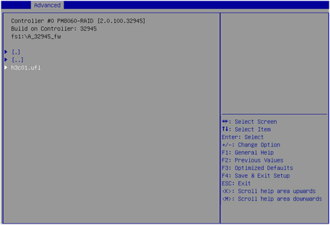
4. On the screen as shown in Figure 55, select the .ufi file and press Enter.
Figure 55 Selecting the update file
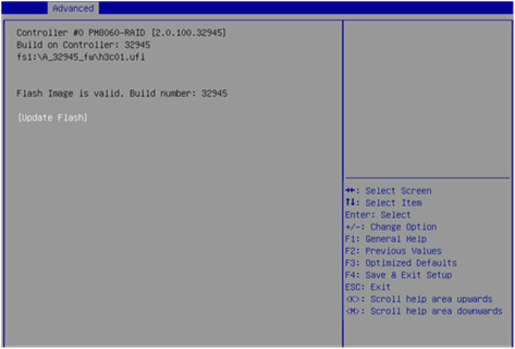
5. On the screen as shown in Figure 56, select Update Flash, and press Enter to start the update process. Wait until the update process is complete.
Figure 56 Selecting Update Flash
6. After the update is complete, press F4. On the dialog box that opens, select Yes to reboot the device and make the update take effect.
Enabling RAID rebuilding
If hot spare drives are not configured, you can perform this task to enable RAID rebuilding manually. If hot spare drives are configured, the system performs RAID rebuilding as required after a drive replacement, which is not affected by the status of the RAID rebuilding feature.
To enable RAID rebuilding:
1. On the storage controller configuration screen as shown in Figure 57, select Controller Settings, and press Enter.
Figure 57 Storage controller configuration screen
2. On the screen as shown in Figure 58, select Controller Configuration, and press Enter.
Figure 58 Controller Settings screen
3. On the screen as shown in Figure 59, set Automatic Failover to Enabled.
Figure 59 Controller Configuration screen
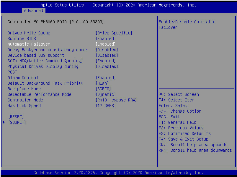
4. Select SUBMIT and then press Enter.
Migrating RAID levels
You can perform RAID level migration for the RAID-P430-M1 and RAID-P430-M2 storage controllers only by using ARCCONF commands. For more information, contact Technical Support.
Expanding RAID capacity
You can perform RAID capacity expansion for the RAID-P430-M1 and RAID-P430-M2 storage controllers only by using ARCCONF commands. For more information, contact Technical Support.
Configuring RAID arrays in legacy mode
This section describes how to configure RAID arrays through a storage controller in legacy mode. For more information about how to enter the BIOS and set the boot mode to legacy, see the BIOS user guide for the server.
RAID array configuration tasks at a glance
To configure RAID arrays in legacy mode, perform the following tasks:
· Accessing the storage controller configuration screen
· Switching the storage controller operating mode
· (Optional.) Configuring boot options
· (Optional.) Deleting RAID arrays
· (Optional.) Uninitializing drives
· (Optional.) Erasing drives
· (Optional.) Locating drives
· (Optional.) Modifying storage controller settings
Accessing the PMC RAID management screen
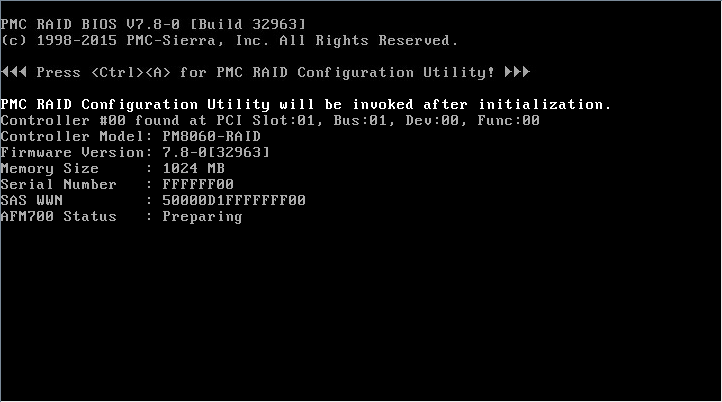
1. During server POST, press Ctrl+A when the screen as shown in Figure 60 opens.
Figure 60 Pressing Ctrl+A as prompted during server POST
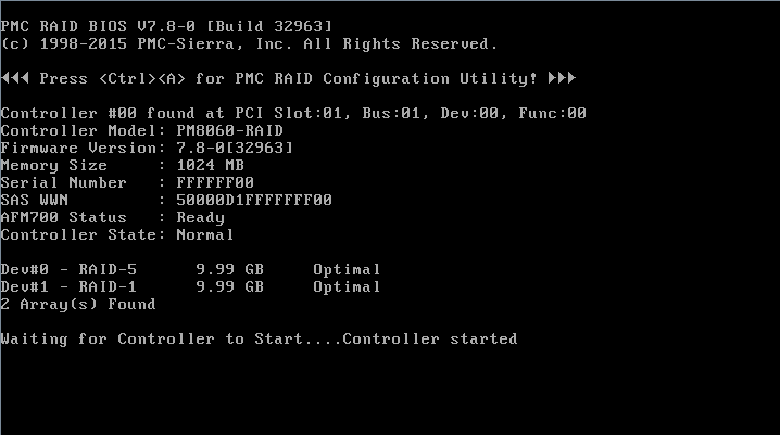
2. The screen as shown in Figure 61 opens, which displays the storage controller version and status information.
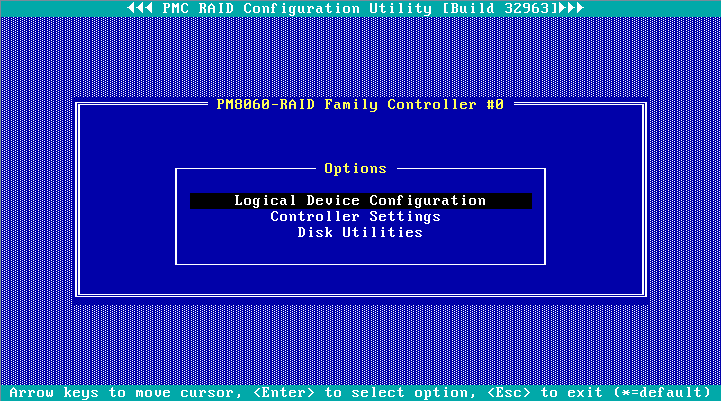
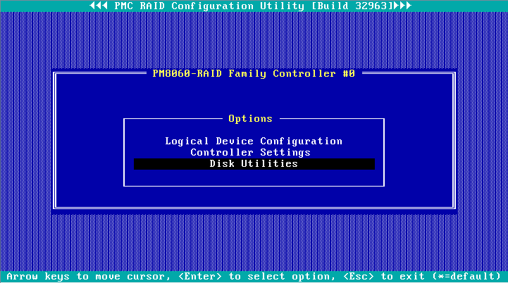
3. The PMC RAID management screen as shown in Figure 62 opens.
Table 6 describes the configuration options. For how to navigate screens and modify settings, see the operation instructions at the bottom.
Figure 62 PMC RAID management screen
|
Option |
Description |
|
Logical Device Configuration |
Select Logical Device Configuration to perform the following tasks: · Manage RAID arrays. · Create RAID arrays. · Initialize or uninitialize drives. · Erase drives. · Configure boot options. |
|
Controller Settings |
Select Controller Settings to perform the following tasks: · Modify the storage controller operating mode. · Restore the default configuration for a storage controller. |
|
Disk Utilities |
Select Disk Utilities to perform the following tasks: · Format drives. · Locate physical drives. |
Switching the storage controller operating mode
1. On the PMC RAID management screen as shown in Figure 63, select Controller Settings, and press Enter.
Figure 63 PMC RAID management screen

2. On the screen as shown in Figure 64, select Controller Configuration, and press Enter.
Figure 64 Controller Settings screen

3. On the screen as shown in Figure 65, select Controller Mode, and press Enter.
Figure 65 Controller Configuration screen
4. On the screen as shown in Figure 66, select a storage controller operating mode (Table 7 describes the storage controller operating modes), and press Enter.
Figure 66 Selecting a storage controller operating mode
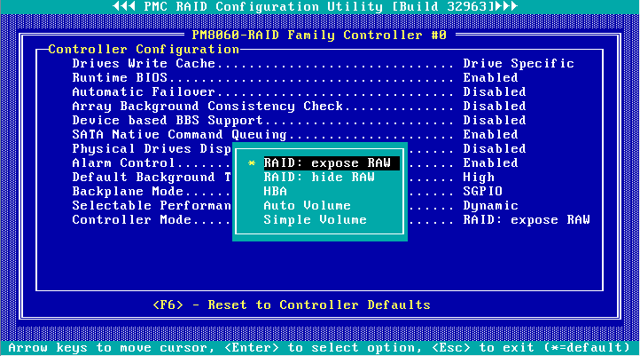
Table 7 Storage controller operating modes
|
Operating mode |
Description |
|
RAID: expose RAW |
All RAID functions can be used. Raw physical drives are exposed to the system. |
|
RAID: hide RAW |
All RAID functions can be used. Raw physical drives are not exposed to the system. |
|
HBA |
RAID functions are disabled. Raw physical drives are exposed to the system. Before setting this mode, you must delete all RAID arrays and hot spare drives, and perform the Uninitializing drives operation for all drives. |
|
Auto Volume |
In this mode, raw physical drives with system partitions are exposed to the system, and physical drives without system partitions are configured as simple volumes. Before setting this mode, you must delete all RAID arrays and hot spare drives in the system. |
|
Simple Volume |
In this mode, only non-redundant RAID arrays with the simple volume level (each contains only one drive) can be created. RAID arrays with other RAID levels cannot be created. Before setting this mode, you must delete all RAID arrays and hot spare drives in the system. |
5. Reboot the operating system to make the storage controller operating mode configuration take effect.
Scanning drives
The storage controller might fail to timely recognize drives after the drives are hot swapped. To solve this problem, you can scan drives.
To scan drives:
1. On the PMC RAID management screen as shown in Figure 67, select Logical Device Configuration, and press Enter.
Figure 67 PMC RAID management screen

2. On the screen as shown in Figure 68, select Rescan Drives, and press Enter.
Figure 68 Logical Device Configuration screen
Initializing drives
Initializing a drive is to divide a small partition in the drive for saving the RAID information. A raw drive must be initialized before it is used for creating a RAID array or configured as a hot spare drive.
To initialize drives:
1. On the PMC RAID management screen as shown in Figure 69, select Logical Device Configuration, and press Enter.
Figure 69 PMC RAID management screen

2. On the screen as shown in Figure 70, select Initialize Drives, and press Enter.
Figure 70 Logical Device Configuration screen
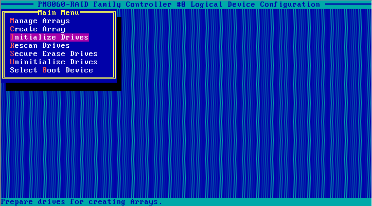
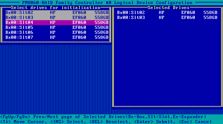
3. On the screen as shown in Figure 71, navigate to the drive that you want to initialize, and press Insert to select the drive. Repeat this step to select more drives. Then, press Enter.
Figure 71 Selecting and initializing drives
Configuring RAID arrays
1. On the PMC RAID management screen as shown in Figure 72, select Logical Device Configuration, and press Enter.
Figure 72 PMC RAID management screen

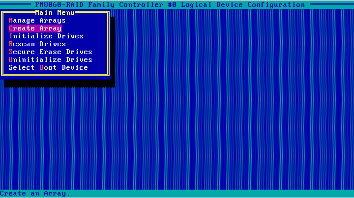
2. On the screen as shown in Figure 73, select Create Array, and press Enter.
Figure 73 Logical Device Configuration screen
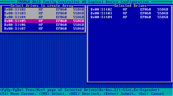
3. On the screen as shown in Figure 74, navigate to the drive to be configured for a RAID array, and press Insert to select the drive. Repeat this step to select more drives. Then, press Enter.
4. On the screen as shown in Figure 75, set the Array Type, Array Label, Array Size, Stripe Size, Read Caching, Write Caching, and Create RAID via parameters, select Done, and press Enter.
Table 8 describes the parameters.
Figure 75 Setting RAID parameters
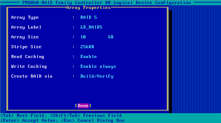
Table 8 Configuration parameters
|
Parameter |
Description |
|
Array Type |
Select a RAID level, which determines the performance, fault tolerance capability, and capacity of the logical drive. |
|
Array Label |
RAID array name, which must be manually entered. |
|
Array Size |
RAID array capacity. |
|
Stripe Size |
Strip size, which determines the data block size of a stripe on each drive. |
|
Read Caching |
Read cache. |
|
Write Caching |
Write cache. |
|
Create RAID via |
Select a method for initializing the RAID array. |
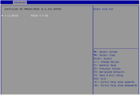
5. After the RAID array is created, select Manage Arrays, and press Enter on the screen as shown in Figure 76.
Figure 76 Selecting Manage Arrays
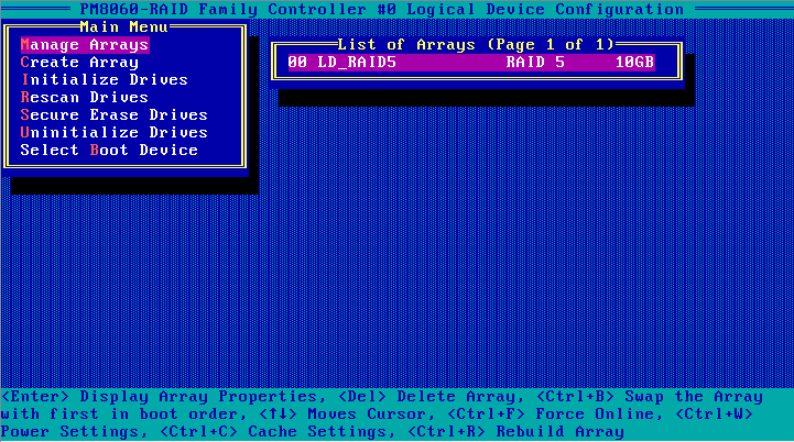
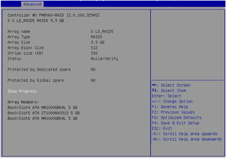
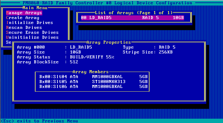
6. On the screen as shown in Figure 77, select the RAID array that you want to view, and press Enter to view the RAID array details (including the RAID array name, RAID level, and member drives).
Figure 77 Viewing RAID array information
Configuring boot options
This section describes how to configure boot options. You can configure a logical drive or physical drive as the first boot option.
Configuring a logical drive as the first boot option
Only a logical drive in Optimal state can be configured as the first boot option.
To configure a logical drive as the first boot option:
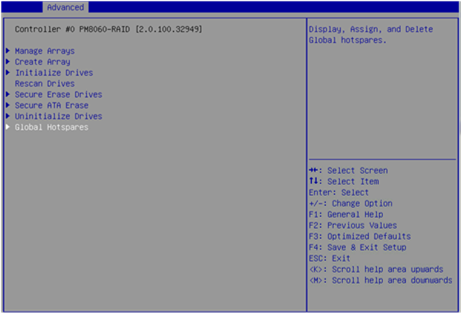
1. On the PMC RAID management screen as shown in Figure 78, select Logical Device Configuration, and press Enter.
Figure 78 PMC RAID management screen
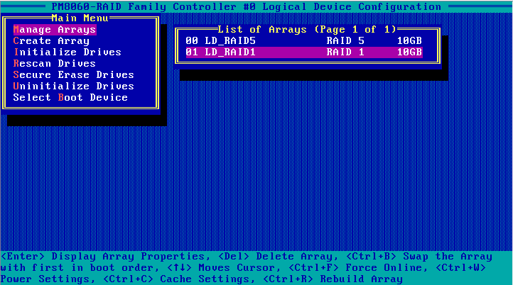
2. On the screen as shown in Figure 79, select Manage Arrays, and press Enter.
Figure 79 Logical Device Configuration screen
3. On the screen as shown in Figure 80, select a RAID array, and press Ctrl+B to configure it as the first boot option.
Figure 80 Selecting the RAID array to be configured as the first boot option

Configuring a physical drive as the first boot option
Only a raw physical drive can be configured as the first boot option. To configure a physical drive in any other state as the first boot option, you must first perform the Uninitializing drives operation for the drive.
In legacy mode, after you configure the storage controller to operate in HBA mode, you must configure a raw drive as the first boot option. Otherwise, the operating system cannot be installed or started.
To configure a physical drive as the first boot option:
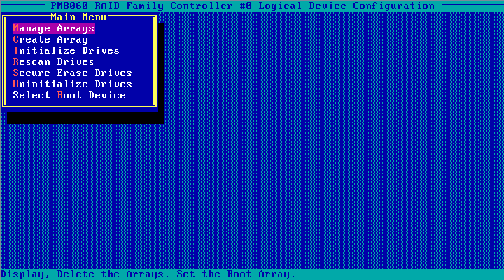
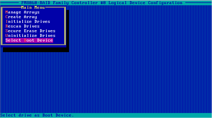
1. On the PMC RAID management screen, select Logical Device Configuration, and press Enter.
2. On the screen as shown in Figure 81, select Select Boot Device, and press Enter.
Figure 81 Logical Device Configuration screen
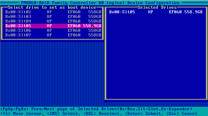
3. On the screen as shown in Figure 82, navigate to the drive to be used as the boot device, press Insert to select the drive, and press Enter.
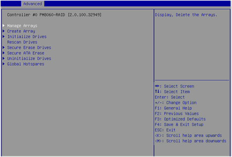
Deleting RAID arrays
1. On the PMC RAID management screen as shown in Figure 83, select Logical Device Configuration, and press Enter.
Figure 83 PMC RAID management screen

2. On the screen as shown in Figure 84, select Manage Arrays, and press Enter.
Figure 84 Logical Device Configuration screen

3. On the screen as shown in Figure 85, select the RAID array to be deleted, and press Delete to delete it.
Figure 85 Deleting a RAID array
Uninitializing drives
|
|
IMPORTANT: When the storage controller operating mode is HBA, you cannot uninitialize drives. To uninitialize these drives, you must first set the storage controller operating mode to RAID: hide RAW, RAID: expose RAW, Auto Volume, or Simple Volume. |
Perform this task to clear data, Adaptec metadata, and reserved space on drives, and remove the system partitions. After a drive in Ready state is uninitialized, it returns to the raw state.
To uninitialize drives:
1. On the PMC RAID management screen, select Logical Device Configuration, and press Enter.
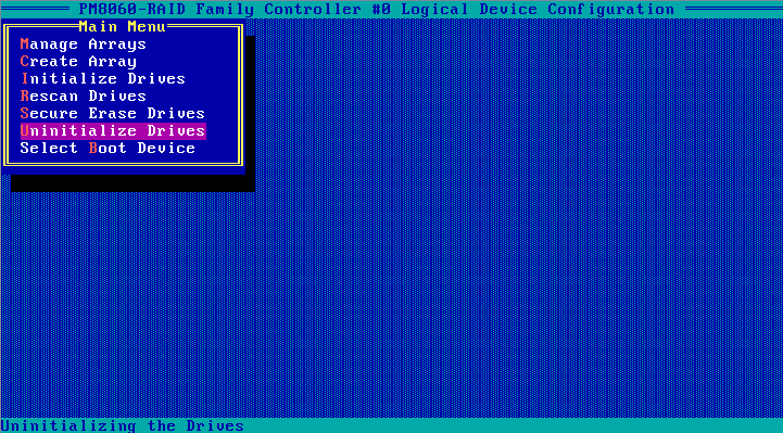
2. On the screen as shown in Figure 86, select Uninitialize Drives, and press Enter.
Figure 86 Logical Device Configuration screen
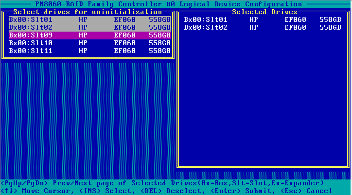
3. On the screen as shown in Figure 87, navigate to the drive that you want to uninitialize, and press Insert to select the drive. Repeat this step to select more drives. Then, press Enter to uninitialize the selected drives.
Figure 87 Selecting and uninitializing drives
Erasing drives
|
|
CAUTION: · To avoid data loss, do not enter the operating system and read or write the drives during the drive erasing process. · To avoid drive failure, do not perform any other operating during the drive erasing process. |
To erase drives:
1. On the PMC RAID management screen as shown in Figure 88, select Logical Device Configuration, and press Enter.
Figure 88 PMC RAID management screen

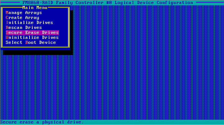
2. On the screen as shown in Figure 89, select Secure Erase Drives, and press Enter.
Figure 89 Logical Device Configuration screen
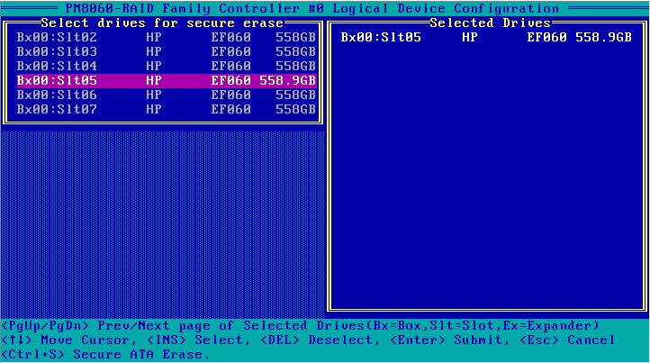
3. On the screen as shown in Figure 90, navigate to the drive that you want to erase, and press Insert to select the drive. Repeat this step to select more drives. Then, press Enter.
Locating drives
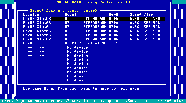
1. On the PMC RAID management screen as shown in Figure 91, select Disk Utilities, and press Enter.
Figure 91 PMC RAID management screen
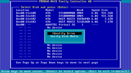
2. On the screen as shown in Figure 92, you can view the drive information. Select the drive to be operated, and press Enter.
Figure 92 Disk Utilities screen
3. On the screen as shown in Figure 93, select Identify Drive and press Enter. The Fault/UID LED on the drive turns steady blue.
Modifying storage controller settings
Perform this task to view the storage controller configuration information, restore the default configuration for the storage controller, and modify the storage controller settings.
To modify storage controller settings:
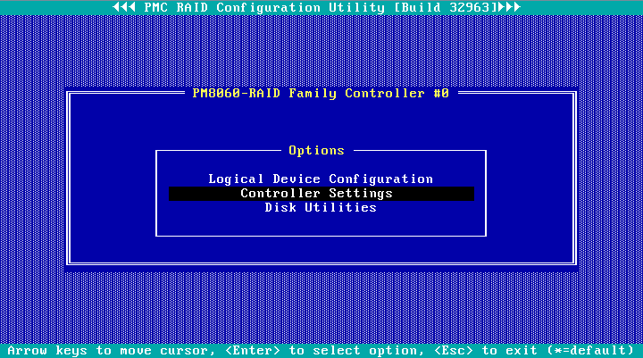
1. On the PMC RAID management screen as shown in Figure 94, select Controller Settings, and press Enter.
Figure 94 PMC RAID management screen
2. On the screen as shown in Figure 95, select Controller Configuration, and press Enter.
Figure 95 Controller Settings screen

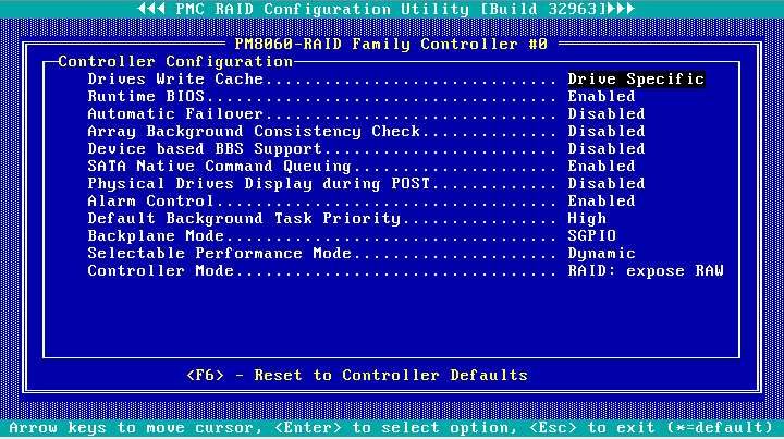
3. On the screen as shown in Figure 96, you can view or modify the basic configuration information for the storage controller. Press F6 to restore the default configuration for the storage controller.
You can set the storage controller operating mode, backplane mode, whether to display physical drives during POST, and RAID rebuilding status.
Figure 96 Controller Configuration screen