- Table of Contents
-
- H3C Servers Storage Controller User Guide-6W107
- 00-Preface
- 01-Storage controller overview
- 02-Storage controller features
- 03-Configuring an embedded RSTe RAID controller
- 04-Configuring an NVMe VROC module
- 05-Configuring a P430 storage controller
- 06-Configuring a 1000 storage controller
- 07-Configuring a 9361, 9440, 9460, L460, P5408, or H5408 storage controller
- 08-Configuring an H460, P460, P240 or P4408 storage controller
- 09-Configuring a 9300 storage controller
- 10-Configuring a 9311 storage controller
- 11-Configuring an LSI 9400 or 9500 series storage controller
- 12-Configuring a RAID-MARVELL-SANTACRUZ-LP-2i storage controller
- 13-Appendix A Troubleshooting storage controllers
- 14-Appendix B RAID arrays and fault tolerance
- Related Documents
-
03-Configuring an embedded RSTe RAID controller
Configuring the embedded RSTe RAID controller or VROC SATA RAID controller
Rack servers, blade servers, and compute modules may provide embedded RSTe RAID controllers.
About the embedded RSTe RAID controller
The embedded Intel Rapid Storage Technology enterprise (RSTe) RAID controller (referred to as VROC SATA RAID controller for G5 servers) is embedded on the southbridge of the system board. Integrating AHCI and RAID programs, the RAID controller is mainly used to manage Intel chip set-based drives, check the status of the drives, and provide RAID capacity for systems that use SATA drives. If the RAID controller has multiple drives attached, you can configure RAID arrays to protect data and improve read/write performance.
If you use the embedded RSTe RAID controller to configure RAID, you can create a maximum of two logical drives with a physical drive. The second logical drive will use the remaining capacity of the physical drive, and the logical drive size cannot be adjusted.
The RAID controller has one SATA controller and one sSATA controller. For the positions of the controllers, see the user guide of the server.
For the embedded RAID controller, you can configure RAID in both UEFI mode and legacy mode.
Features
Operating modes
The RAID controller supports the following operating modes:
· AHCI mode—This is the default mode. In this mode, all physical drives are exposed to the operating system (OS). The drives can be directly used for data storage. Native Command Queuing (NCQ) is supported, which improves the I/O performance of SATA drives.
· RAID mode—In this mode, RAID functions are enabled and RAID arrays can be created on physical drives to improve I/O performance and data security.
|
|
NOTE: · For the new mode to take effect, restart the server after an operating mode change. · The OS might fail to start up after the operating mode of the storage controller is changed. To resolve this issue, reinstall the OS. If the issue persists, contact Technical Support. |
RAID levels
The supported RAID levels vary by storage controller model. For more information about the supported RAID levels of each storage controller, see H3C Servers Storage Controllers Technical Specifications.
Table 1 shows the minimum number of drives required by each RAID level and the maximum number of failed drives supported by each RAID level. For more information about RAID levels, see "Appendix B RAID arrays and fault tolerance."
Table 1 RAID levels and the numbers of drives for each RAID level
|
RAID level |
Min. drives required |
Max. failed drives |
|
RAID 0 |
2 |
0 |
|
RAID 1 |
2 |
1 |
|
RAID 5 |
3 |
1 |
|
RAID 10 |
4 |
2 |
Restrictions and guidelines for RAID configuration
· As a best practice, install drives that do not contain RAID information.
· To avoid degraded RAID performance or RAID creation failures, make sure all drives in the RAID are the same type (HDDs or SSDs) and have the same connector type (SAS or SATA).
· For efficient use of storage, use drives that have the same capacity to build a RAID. If the drives have different capacities, the lowest capacity is used across all drives in the RAID.
· If one drive is used by several logical drives, RAID performance might be affected and maintenance complexities will increase.
Configuring RAID arrays in UEFI mode
This section describes how to configure RAID arrays through an embedded RSTe RAID controller in UEFI mode. For more information about how to enter the BIOS and set the boot mode to UEFI, see the BIOS user guide for the server.
RAID array configuration tasks at a glance
To configure RAID arrays in UEFI mode, perform the following tasks:
· Setting the RSTe operating mode
· Accessing the RSTe configuration screen
· (Optional.) Configuring hot spare drives
· (Optional.) Deleting RAID arrays
Setting the RSTe operating mode
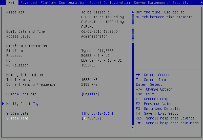
1. During server POST, press Delete, Esc, or F2 as prompted to open the BIOS setup screen as shown in Figure 1.
For how to navigate screens and modify settings, see the operation instructions at the lower right corner.
Figure 1 BIOS setup screen
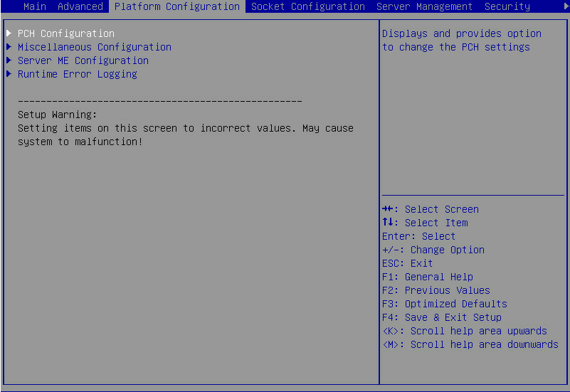
2. On the screen as shown in Figure 2, select Platform Configuration > PCH Configuration, and press Enter.
For G5 servers, the Platform Configuration options are in the Advanced menu.
Figure 2 Platform Configuration screen

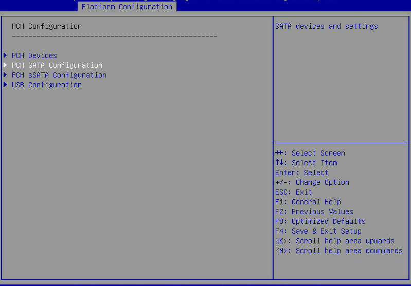
3. On the screen as shown in Figure 3, select PCH SATA Configuration or PCH sSATA Configuration, which corresponds to the two configuration entries of the embedded RSTe RAID controller, and then press Enter.
Figure 3 PCH Configuration screen
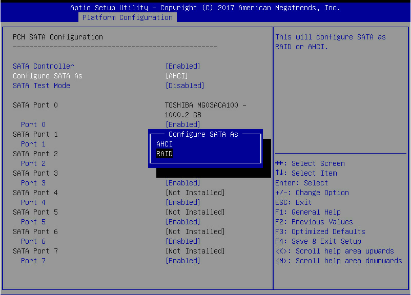
4. On the screen as shown in Figure 4, select Configure SATA As, press Enter, and select an operating mode.
For more information about setting the operating mode for an embedded RSTe RAID controller, see "Features."
Figure 4 Modifying the storage controller operating mode

5. After the configuration is complete, press F4. On the dialog box that opens, select Yes to save the current configuration and reboot the system to complete the storage controller operating mode configuration.
Accessing the RSTe configuration screen
1. Access the BIOS setup screen.
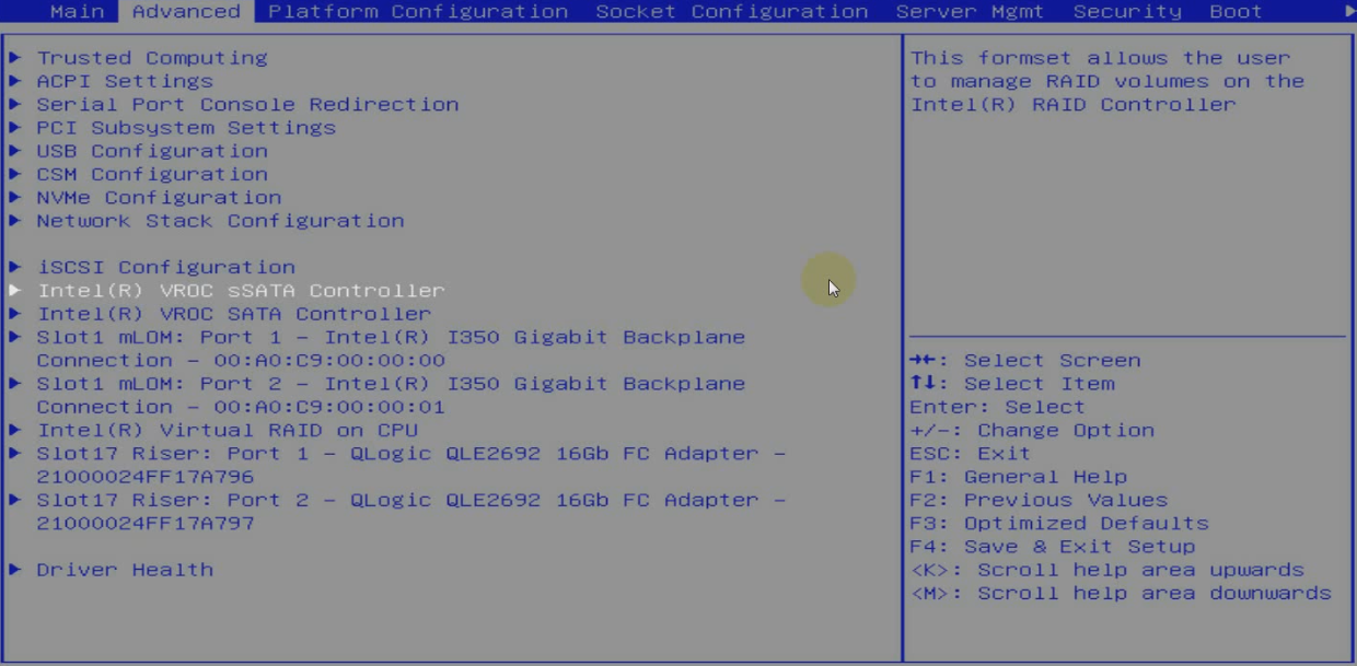
2. On the screen as shown in Figure 5, select Advanced > Intel(R) VROC SATA Controller or Intel(R) VROC sSATA Controller, and press Enter.
|
|
NOTE: For the Intel(R) VROC SATA Controller or Intel(R) VROC sSATA Controller option to appear on the screen shown in Figure 5, make sure the SATA or sSATA controller has been configured to operate in RAID mode. For how to set the operating mode, see "Setting the RSTe operating mode." |
Figure 5 Advanced screen
The RSTe configuration screen as shown in Figure 6 opens.
Figure 6 RSTe configuration screen

Configuring RAID arrays
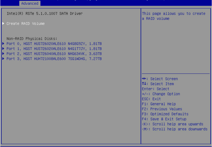
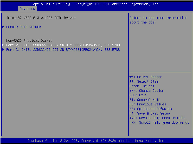
1. On the RSTe configuration screen as shown in Figure 7, select Create RAID Volume, and press Enter.
The Create RAID Volume option is available only when the interface corresponding to the SATA or sSATA controller connects to two or more drives.
Figure 7 Selecting Create RAID Volume
2. On the screen as shown in Figure 8, set the Name, RAID Level, Select Disks, Strip Size, and Capacity parameters, select Create Volume, and press Enter to create the RAID volume.
Table 2 describes the configuration parameters for creating a RAID volume.
Figure 8 Setting RAID parameters
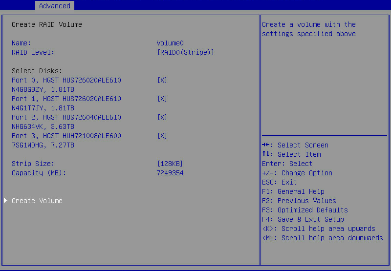
Table 2 Configuration parameters
|
Parameter |
Description |
|
Name |
RAID array name. |
|
RAID Level |
RAID level, which determines the performance, fault tolerance capability, and capacity for the logical drive. |
|
Select Disks |
Select member drives for the RAID array. Available drives are displayed under Select Disks. Press Enter to select drives. [X] indicates that the corresponding drive has been selected. |
|
Strip Size |
Stripe size, which determines the size of the data block that can be written into a stripe on each drive. |
|
Capacity |
Logical drive capacity. |
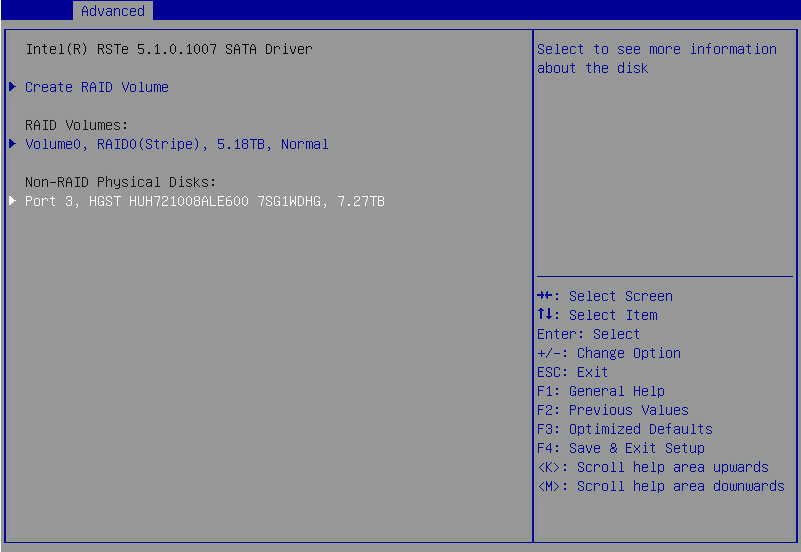
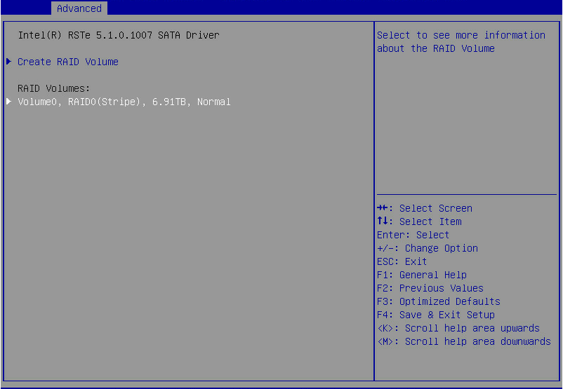
3. The screen as shown in Figure 9 opens.
After the RAID volume is created, the RAID volume is displayed in the RAID Volumes directory. To view details about a RAID volume, select the RAID volume, and press Enter. Details about a RAID volume include the RAID array name, RAID level, and member drives.
Figure 9 Viewing the created RAID volume

Configuring hot spare drives
|
|
CAUTION: With hot spare drives configured, if a RAID level is degraded due to drive failures, hot spare drives replace the failed drives automatically. The system starts RAID rebuilding automatically after accessing the OS. |
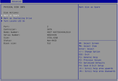
1. On the RSTe configuration screen as shown in Figure 10, select a drive to configure as a hot spare drive, and press Enter.
Figure 10 Selecting a drive for hot spare
2. Select Mark as Spare, and press Enter.
Figure 11 Configuring a spare drive
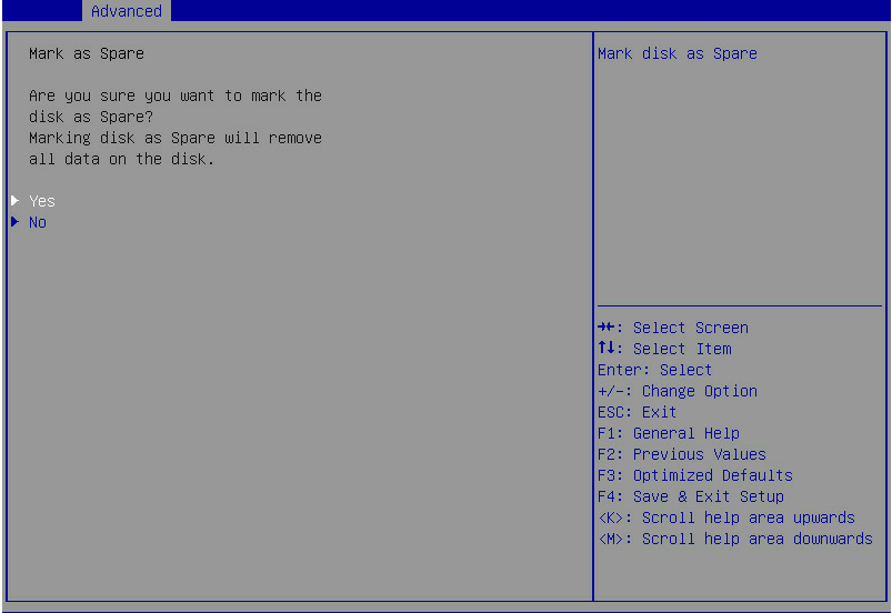
3. On the following screen that opens, select Yes and press Enter.
Figure 12 Confirming the hot spare configuration
Deleting RAID arrays
1. On the RSTe configuration screen as shown in Figure 13, select the RAID volume to be deleted under RAID Volumes, and press Enter.
Figure 13 Selecting the RAID volume to be deleted
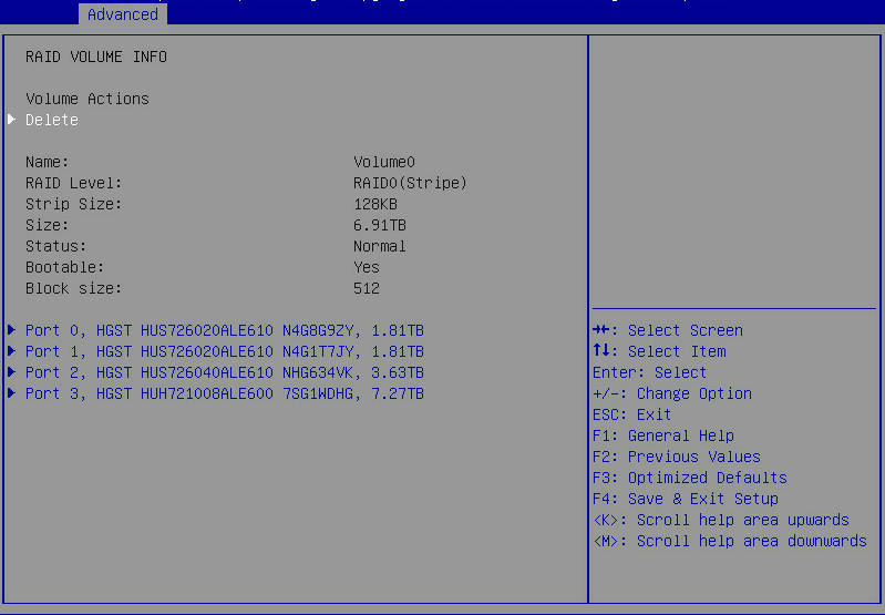
2. On the screen as shown in Figure 14, select Delete and press Enter to delete the selected RAID volume.
Figure 14 RAID volume information screen
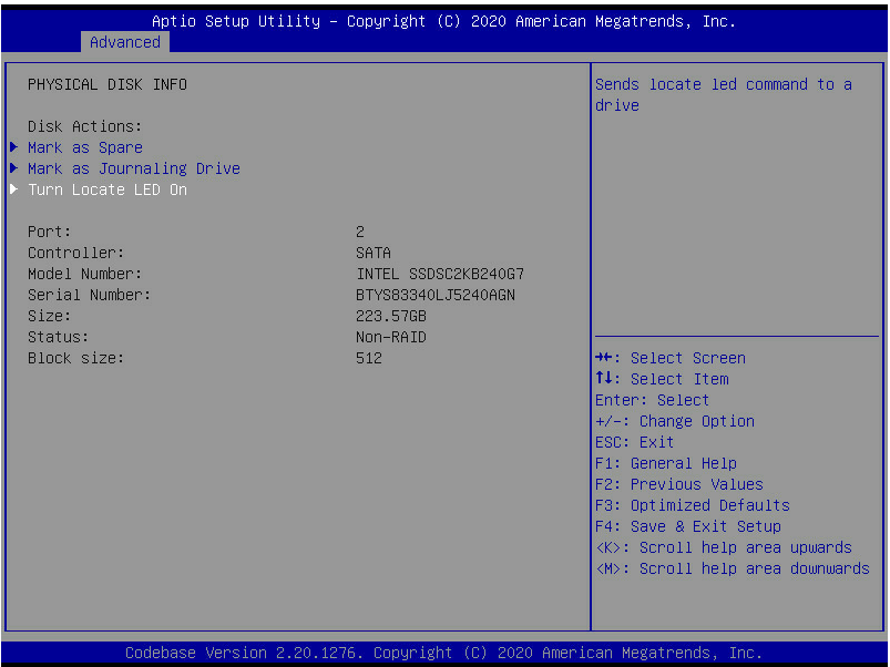
Locating a drive
1. On the RSTe configuration screen as shown in Figure 15, select the RAID volume to locate, and press Enter.
Figure 15 Selecting the RAID volume to delete
2. Select Turn Locate LED On and then press Enter.
For information about drive LEDs, see the user guide for the server.
Figure 16 Locating a logical drive
Initializing a logical drive
The embedded RAID controller automatically initializes the RAID after RAID configuration. After initialization, the logical drive can be used by the OS and the member drives can meet the requirement of the RAID level if the RAID is redundant.
Configuring RAID arrays in legacy mode
This section describes how to configure RAID through an embedded RSTe RAID controller in legacy mode. For more information about how to enter the BIOS and set the boot mode to legacy, see the BIOS user guide for the server.
RAID array configuration tasks at a glance
To configure RAID arrays in legacy mode, perform the following tasks:
· Setting the RSTe operating mode
· Accessing the RSTe configuration screen
· (Optional.) Configuring hot spare drives
· (Optional.) Deleting RAID arrays
Setting the RSTe operating mode
1. Access the BIOS setup screen.
2. On the screen as shown in Figure 17, select Platform Configuration > PCH Configuration, and press Enter.
Figure 17 Platform Configuration screen
3. On the screen as shown in Figure 18, select PCH SATA Configuration or PCH sSATA Configuration, which corresponds to the two configuration entries of the embedded RSTe RAID controller, and then press Enter.
Figure 18 PCH Configuration screen

4. On the screen as shown in Figure 19, select Configure SATA As, press Enter, and select an operating mode.
Figure 19 Modifying the storage controller operating mode
Accessing the RSTe configuration screen
This section describes how to access the legacy BIOS configuration screen. To enter the RSTe configuration screen, make sure a minimum of one embedded RSTe RAID controller is configured to operate in RAID mode and each controller connects to a minimum of two drives. For how to set the operating mode, see "Setting the RSTe operating mode."
To access the RSTe configuration screen:
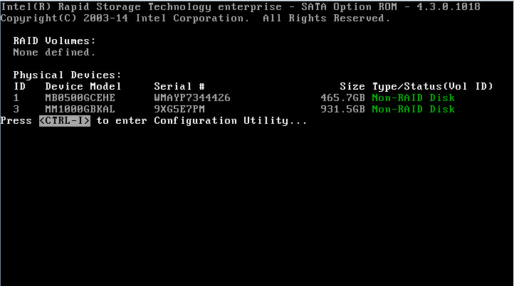
1. Power on or reboot the server.
2. When the screen is as shown in Figure 20 during server POST, press Ctrl+I.
|
|
NOTE: If both sSATA and SATA controllers are configured to operate in RAID mode, the prompt Press <CTRL-I> to enter Configuration Utility appears twice during server POST, which corresponds to the sSATA controller and SATA controller. Select a controller according to the drives to be configured for a RAID array. |
The RSTe configuration screen as shown in Figure 21 opens. Table 3 describes the configuration screen. For how to navigate screens and modify settings, see the operation instructions at the bottom of the screen.
Figure 21 RSTe configuration screen
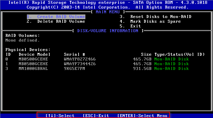
Table 3 RSTe configuration screen description
|
Section |
Description |
|
MAIN MENU |
In the MAIN MENU section on the upper part of the page, you can perform the following tasks: · Create RAID arrays. · Delete RAID arrays. · Reset drives to non-RAID. · Mark drives as spare. · Exit. |
|
DISK/VOLUME INFORMATION |
In the DRIVE/VOLUME INFORMATION section on the lower part of the page, you can view brief information about existing RAID arrays and physical drives. |
Configuring RAID arrays
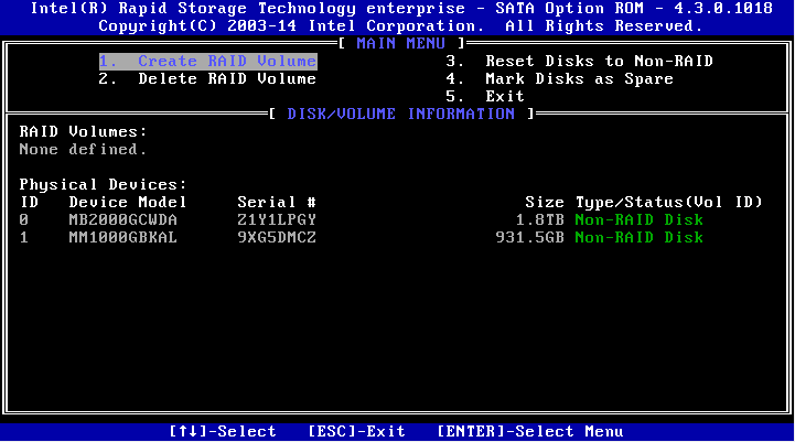
1. On the RSTe configuration screen as shown in Figure 22, select Create RAID Volume, and press Enter.
Figure 22 RSTe configuration screen
2. On the screen as shown in Figure 23, set the Name, RAID Level, Disks, Strip Size, and Capacity parameters, select Create Volume, and press Enter to create the RAID volume.
Table 4 describes the configuration parameters for creating a RAID volume.
Figure 23 Creating a RAID volume
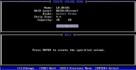
Table 4 Configuration parameters
|
Configuration |
Description |
|
Name |
RAID array name. |
|
RAID Level |
RAID level, which determines the performance, fault tolerance capability, and capacity for the logical drive. |
|
Disks |
Select member drives for the RAID array. To select a drive, select Disks, press Enter, navigate to the drive, and then press the space bar. |
|
Strip Size |
Stripe size, which determines the size of the data block that can be written into a stripe on each drive. |
|
Capacity |
Logical drive capacity. |
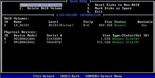
3. The screen as shown in Figure 24 opens.
The screen displays details about the created RAID volume, including the RAID array name, RAID level, and member drives.
Figure 24 RAID volume information screen
Configuring hot spare drives
|
|
CAUTION: With hot spare drives configured, if a RAID level is degraded due to drive failures, hot spare drives replace the failed drives automatically. The system starts RAID rebuilding automatically after accessing the OS. |
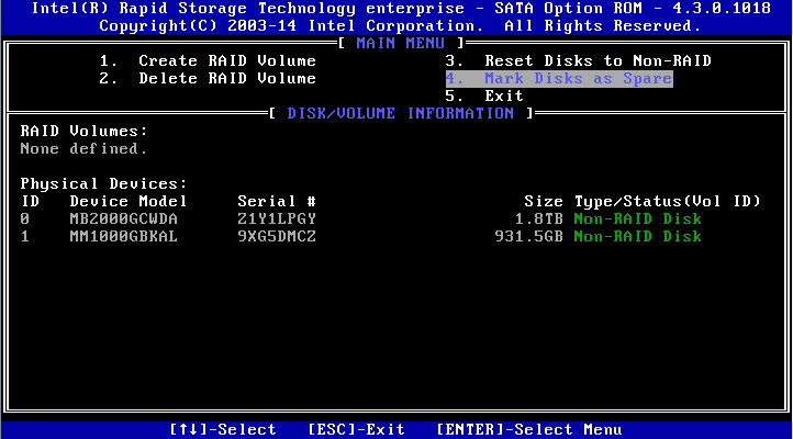
1. On the RSTe configuration screen, select Mark Disks as Spare, and press Enter.
Figure 25 RSTe configuration screen
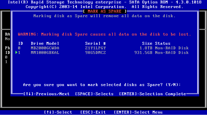
2. Select a drive for hot spare, press SPACE, and then press Enter. On the prompt that opens, enter y and press Enter.
Figure 26 Selecting a drive for hot spare
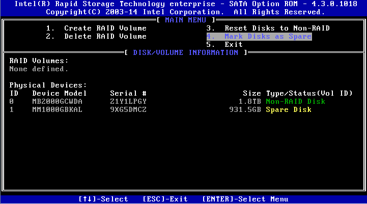
3. View the configured hot spare information on the RSTe configuration screen.
Figure 27 Viewing hot spare information
Deleting RAID arrays
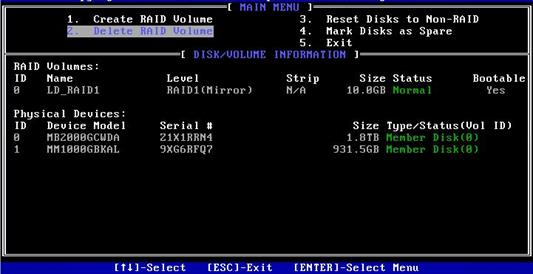
1. On the RSTe configuration screen as shown in Figure 28, select Delete RAID Volume, and press Enter.
Figure 28 RSTe configuration screen
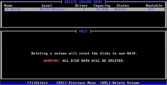
2. On the screen as shown in Figure 29, select the RAID volume to be deleted, and press Delete.
Figure 29 Selecting the RAID volume to be deleted