- Table of Contents
-
- H3C Servers Storage Controller User Guide-6W107
- 00-Preface
- 01-Storage controller overview
- 02-Storage controller features
- 03-Configuring an embedded RSTe RAID controller
- 04-Configuring an NVMe VROC module
- 05-Configuring a P430 storage controller
- 06-Configuring a 1000 storage controller
- 07-Configuring a 9361, 9440, 9460, L460, P5408, or H5408 storage controller
- 08-Configuring an H460, P460, P240 or P4408 storage controller
- 09-Configuring a 9300 storage controller
- 10-Configuring a 9311 storage controller
- 11-Configuring an LSI 9400 or 9500 series storage controller
- 12-Configuring a RAID-MARVELL-SANTACRUZ-LP-2i storage controller
- 13-Appendix A Troubleshooting storage controllers
- 14-Appendix B RAID arrays and fault tolerance
- Related Documents
-
08-Configuring an H460, P460, P240 or P4408 storage controller
Configuring an H460, P460, P2404, or P4408 series storage controller
About H460, P460, P2404, and P4408 storage controllers
The storage controllers support 12-Gbps data channels. Some storage controllers support caching, which greatly improves performance and data security. For more information, contact Technical Support.
This chapter is available for the following storage controllers:
· HBA-H460-M1
· HBA-H460-B1
· RAID-P460-M2
· RAID-P460-B2
· RAID-P460-M4
· RAID-P460-B4
· RAID-P2404-Mf-4i
· RAID-P4408-Mf-8i
· RAID-P4408-Ma-8i-2GB
Features
Operating modes
The storage controller supports the following operating modes:
· HBA mode—In this mode, physical drives attached to the storage controller are exposed as raw drives and RAID functions are disabled.
· RAID mode—In this mode, RAID functions are enabled and RAID arrays can be created on physical drives. Only logical drives are exposed to the operating system.
· Mixed mode—This is the default mode. In this mode, RAID functions are enabled and RAID arrays can be created on physical drives. Both logical drives and raw physical drives are exposed to the operating system.
|
|
IMPORTANT: · If the storage controller has RAID configuration, you must clear RAID configuration before changing the operation mode of the storage controller to HBA mode. The new operating mode takes effect after the server reboots. · For the new mode to take effect, restart the server after an operating mode change. · The operating system might fail to start up after the operating mode of the storage controller is changed. To resolve this issue, reinstall the operating system. If the issue persists, contact Technical Support. |
RAID levels
The supported RAID levels vary by storage controller model. For more information about the supported RAID levels of each storage controller, see H3C Servers Storage Controllers Technical Specifications.
Table 1 shows the minimum number of drives required by each RAID level and the maximum number of failed drives supported by each RAID level. For more information about RAID levels, see "Appendix B RAID arrays and fault tolerance."
Table 1 RAID levels and the numbers of drives for each RAID level
|
RAID level |
Min. drives required |
Max. failed drives |
|
RAID 0 |
1 |
0 |
|
RAID 1 |
2 |
1 |
|
RAID 1 ADM |
3 |
2 |
|
RAID 5 |
3 |
1 |
|
RAID 6 |
4 |
2 |
|
RAID 10 |
4 |
n, where n is the number of RAID 1 arrays in the RAID 10 array. |
|
RAID 10 ADM |
6 |
2n, where n is the number of RAID 1 ADMs in the RAID 10 ADMs. |
|
RAID 50 |
6 |
n, where n is the number of RAID 5 arrays in the RAID 50 array. |
|
RAID 60 |
8 |
2n, where n is the number of RAID 6 arrays in the RAID 60 array. |
Hot spare drives
You can configure hot spare drives to improve data security. A hot spare drive is a standby drive that does not store any data. When a drive in a redundant RAID fails, a spare drive automatically replaces the failed drive and rebuilds the data of the failed drive.
The storage controller supports the following types of hot spare drives. For more information about hot spare drive types, see "Storage controller features."
· Dedicated spare drive.
· Auto replace spare drive.
Restrictions and guidelines for RAID configuration
As a best practice, install drives that do not contain RAID information.
To avoid degraded RAID performance or RAID creation failures, make sure all drives in the RAID are the same type (HDDs or SSDs) and have the same connector type (SAS or SATA).
For efficient use of storage, use drives that have the same capacity to build a RAID. If the drives have different capacities, the lowest capacity is used across all drives in the RAID.
If one drive is used by several logical drives, RAID performance might be affected and maintenance complexities will increase.
Configuring RAID arrays in UEFI mode
This section describes how to configure RAID arrays through a storage controller in UEFI mode. For more information about how to enter the BIOS and set the boot mode to UEFI, see the BIOS user guide for the server.
RAID array configuration tasks at a glance
To configure RAID arrays in UEFI mode, perform the following tasks:
· Accessing the storage controller configuration screen
· Switching the operating mode
· (Optional.) Configuring hot spare drives
· (Optional.) Deleting a RAID array
· (Optional.) Viewing drive information
· (Optional.) Locating drives
· (Optional.) Erasing drives
· (Optional.) Viewing basic storage controller information
· (Optional.) Modifying storage controller settings
· (Optional.) Clearing storage controller configuration information
· (Optional.) Upgrading the storage controller firmware online
Accessing the storage controller configuration screen
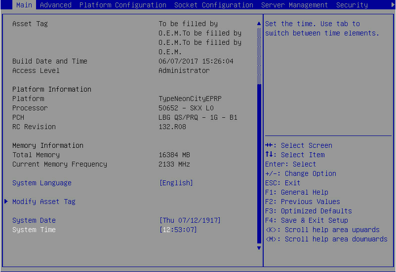
1. Access the BIOS. Press Delete, Esc, or F2 as prompted during server POST to open the BIOS setup screen as shown in Figure 1. For some servers, the Front Page screen opens, and you must select Device Management before proceeding to the next step.
For how to navigate screens and modify settings, see the operation instructions at the lower right corner.
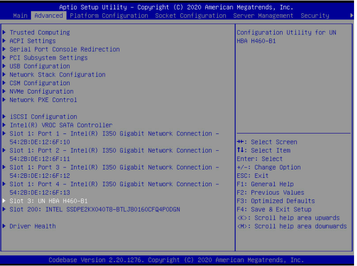
2. On the screen as shown in Figure 2, select Advanced > storage controller model, and press Enter.
In this example, the storage controller model is UN HBA H460-B1.
Figure 2 Selecting UN HBA H460-B1
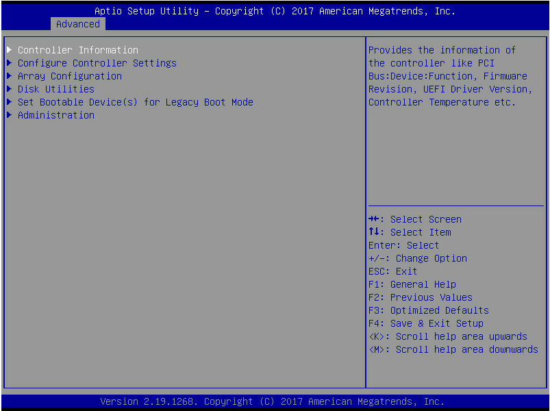
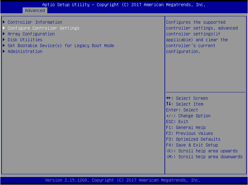
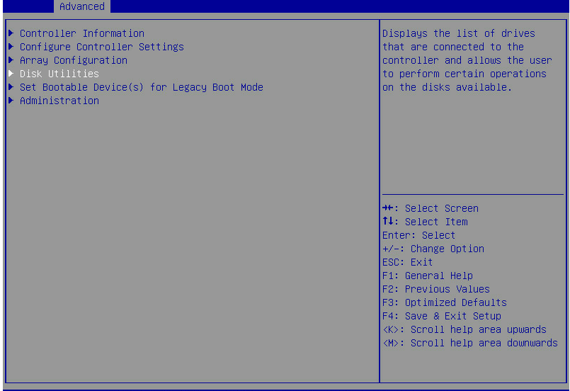
The storage controller configuration screen as shown in Figure 3 opens.
Figure 3 Storage controller configuration screen
Switching the operating mode
If RAID arrays have been created, delete all the RAID arrays before you switch the mode.
To switch the operating mode:
1. On the storage controller configuration screen as shown in Figure 4, select Configure Controller Settings and press Enter.
Figure 4 Storage controller configuration screen
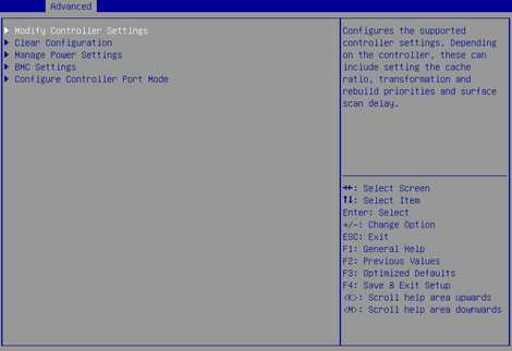
2. On the screen as shown in Figure 5, select Modify Controller Settings or Configure Controller Port Mode, and press Enter.
This section uses Modify Controller Settings as an example.
Figure 5 Configure Controller Settings screen
3. On the screen as shown in Figure 6, change the operating mode for Port CN0 Mode or Port CN1 Mode (as a best practice, make sure their operating modes are the same), select Submit Changes, and press Enter.
Figure 6 Modify Controller Settings screen
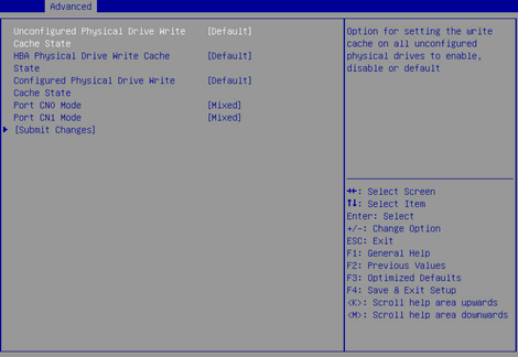
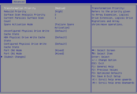
Figure 6 shows a screen with no RAID array configured. If a RAID array is configured, the Modify Controller Settings screen is as shown in Figure 7.
Figure 7 Modify Controller Settings screen
Configuring a RAID array
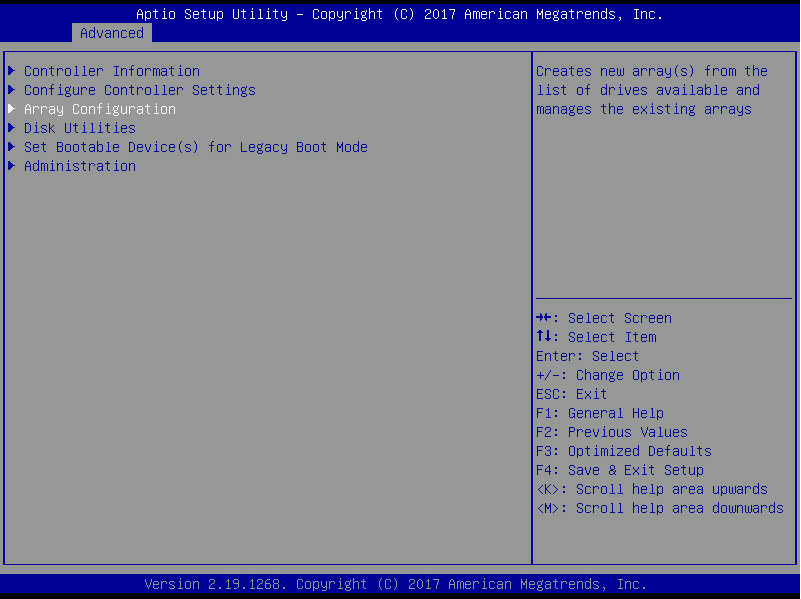
1. On the storage controller configuration screen as shown in Figure 8, select Array Configuration and press Enter.
Figure 8 Storage controller configuration screen
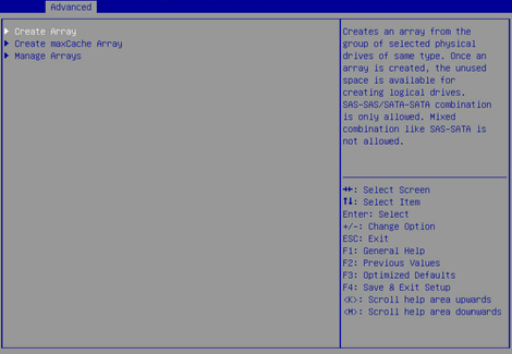
2. On the screen as shown in Figure 9, select Create Array and press Enter.
Figure 9 Array Configuration screen

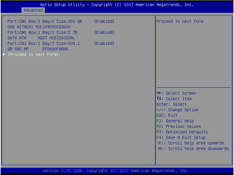
3. On the screen as shown in Figure 10, select the target drives. ([Enabled] following a drive means that the drive has been selected.) Then, select Proceed to next Form and press Enter.
Figure 10 Selecting the target drives
4. On the screen as shown in Figure 11, set the RAID level, select Proceed to next Form, and then press Enter.
Figure 11 Setting the RAID level

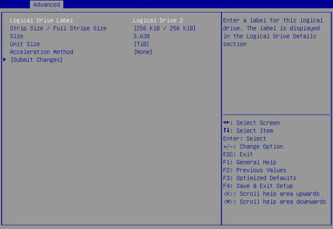
5. On the screen as shown in Figure 12, set the values for Logical Drive Label, Stripe Size/Full Stripe Size, Size, Unit Size, and Acceleration Method. Then, select Submit Changes and press Enter. For more information about the parameter description, see Table 2.
Figure 12 Configuring RAID array parameters
|
Parameter |
Description |
|
Logical Drive Label |
RAID array name. |
|
Stripe Size |
Data block size for each drive. |
|
Size |
Capacity for the logical drive. |
|
Unit Size |
Size for the unit. |
|
Acceleration Method |
Logical drive acceleration method. |
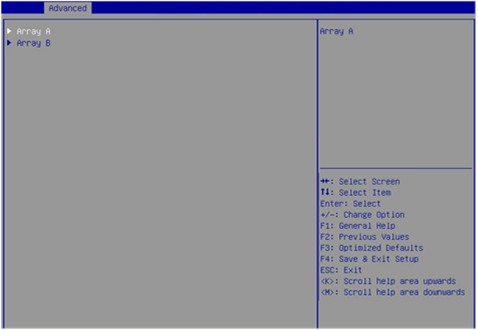
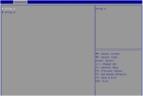
6. After creating the RAID array, select Array Configuration > Manage Arrays and press Enter. On the screen as shown in Figure 13 that opens, select the RAID array you want to view and press Enter.
Figure 13 Selecting a RAID array
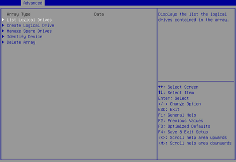
7. On the screen as shown in Figure 14, select List Logical Drives, select the RAID array you want to view and press Enter.
Figure 14 Selecting List Logical Drives
8. On the screen as shown in Figure 15, select Logical Drive 2 and press Enter.
Figure 15 Selecting Logical Drive 2

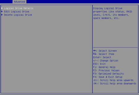
9. On the screen as shown in Figure 16, select Logical Drive Details and press Enter to view detailed information about the RAID array (including RAID array name, level, and drive information).
Figure 16 Selecting Logical Drive Details
Configuring hot spare drives
1. On the storage controller configuration screen as shown in Figure 17, select Array Configuration and press Enter.
Figure 17 Storage controller configuration screen

2. On the screen as shown in Figure 18, select Manage Arrays and press Enter.
Figure 18 Array Configuration screen

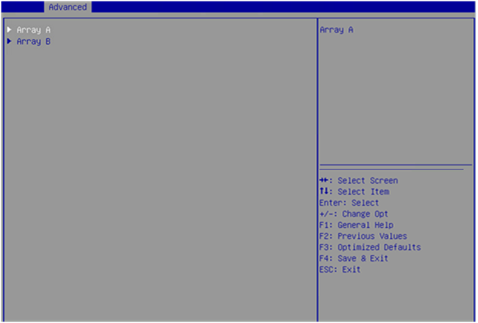
3. On the screen as shown in Figure 19, select the target array and press Enter.
Figure 19 Selecting the target array
4. On the screen as shown in Figure 20, select Manage Spare Drives and press Enter.
Figure 20 Selecting Manage Spare Drivers

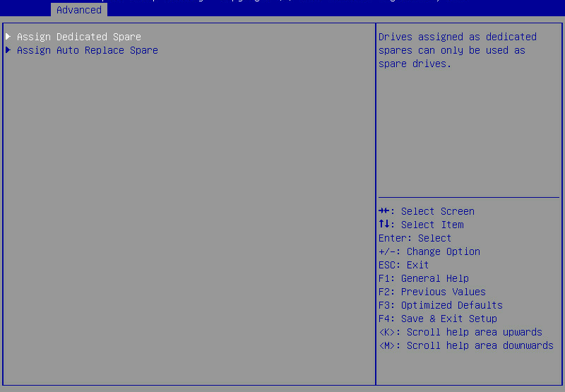
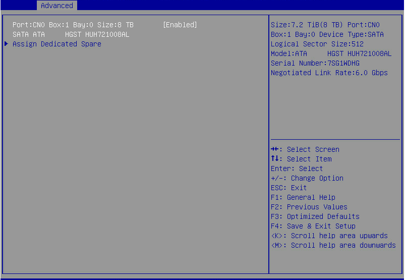
5. On the screen as shown in Figure 21, select Assign Dedicated Spare (for specifying a hot spare drive for the specified array) or Assign Auto Replace Spare (for automatically replacing failed drives) and press Enter.
Figure 21 Selecting the spare type
6. On the screen as shown in Figure 22, select the target drives. ([Enabled] following a drive means that the drive has been selected.) Then, select Assign Dedicated Spare and press Enter.
Figure 22 Selecting the target drives
Deleting a RAID array
This task allows you to delete a RAID array and the logical drives contained in it.
|
|
NOTE: Deleting logical drives in the middle of a RAID array might cause discontinuous sectors on the physical drives of this array. As a consequence, the operation might affect the drive read and write rate and limit the operations on logical drives performed by using RAID array configuration tools. As a best practice to avoid these problems, delete logical drives from back to front in sequence. If you delete logical drives in the middle, wait for all the logical drives to enter normal state before executing any other operations. |
To delete a RAID array:
1. On the storage controller configuration screen as shown in Figure 23, select Array Configuration and press Enter.
Figure 23 Storage controller configuration screen

2. On the screen as shown in Figure 24, select Manage Arrays and press Enter.
Figure 24 Array Configuration screen
3. On the screen as shown in Figure 25, select the target array and press Enter.
Figure 25 Selecting the target array
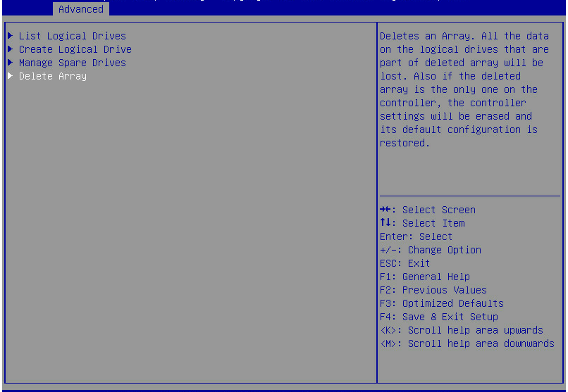
4. On the screen as shown in Figure 26, select Delete Array and press Enter.
Figure 26 Selecting Delete Array
Viewing drive information
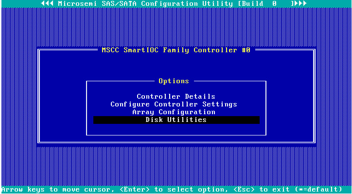
1. On the storage controller configuration screen as shown in Figure 27, select Disk Utilities and press Enter.
Figure 27 Storage controller configuration screen
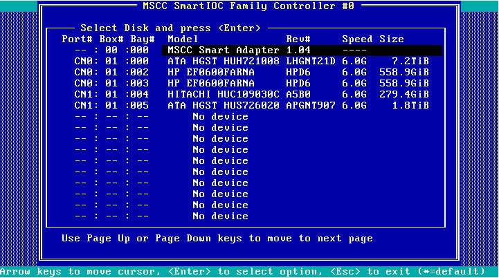
2. On the screen as shown in Figure 28, you can see information about all available drives.
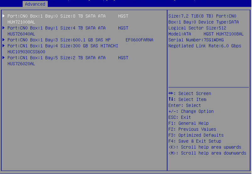
Locating drives
1. Select the target drive on the screen as shown in Figure 28 and press Enter.
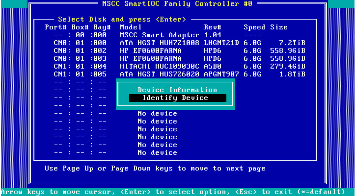
2. On the screen as shown in Figure 29, select Identify Device and press Enter.
Figure 29 Selecting Identify Device
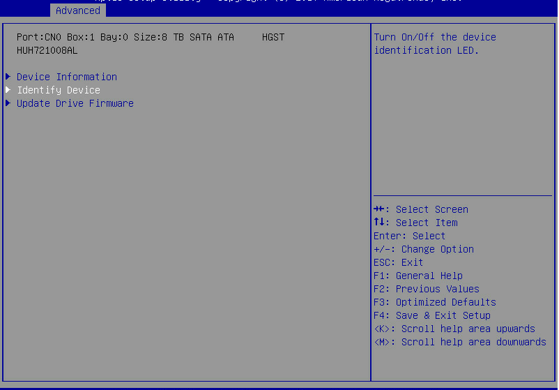
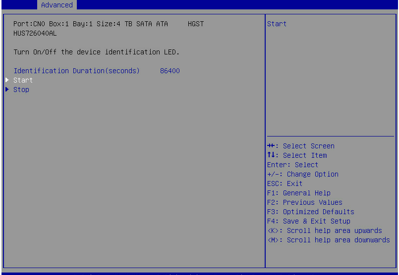
3. On the screen as shown in Figure 30, select Start, and the Fault/UID LED on the drive turns steady blue. If you select Stop, the Fault/UID LED on the drive turns off.
Figure 30 Identifying the drive
Erasing drives
Restrictions and guidelines
You can perform this task only when the storage controller operates in RAID mode.
You can erase only physical drives.
To avoid drive failure, do not power off, restart, or remove the drive during the erasing process.
Procedure
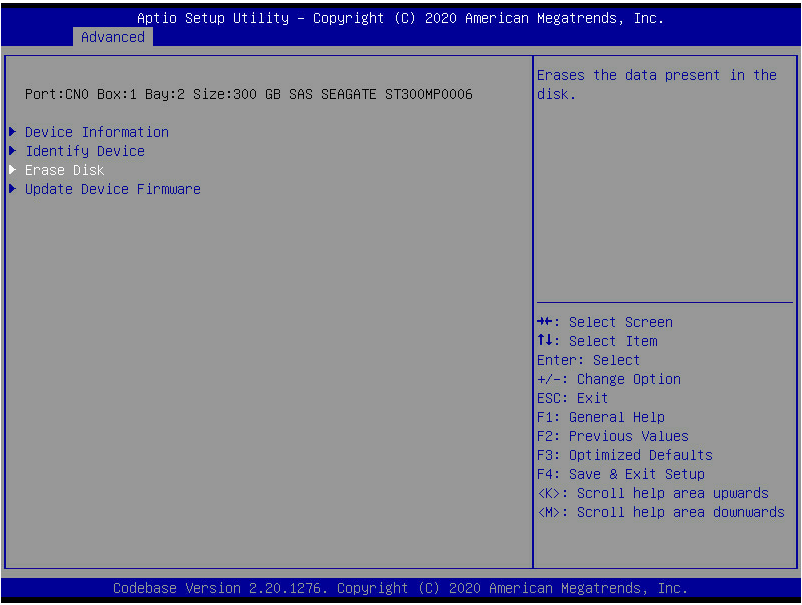
1. On the storage controller configuration screen as shown in Figure 28, select the drive to be erased, and then press Enter.
2. On the screen as shown in Figure 31, select Erase Disk and then press Enter.
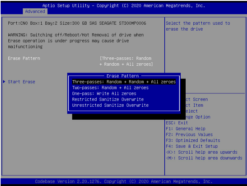
3. On the screen as shown in Figure 32, select the erase pattern, and press Enter.
Figure 32 Selecting the erase pattern
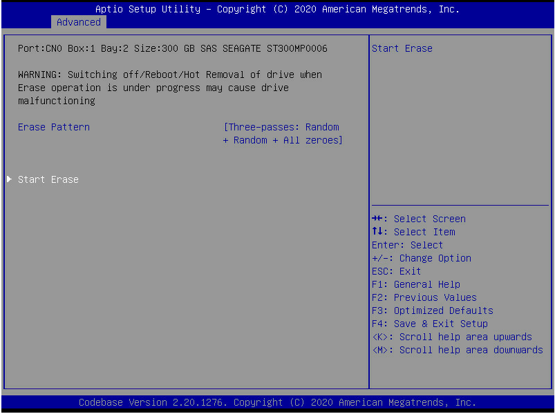
4. On the screen as shown in Figure 33, select Start Erase, and press Enter.
Viewing basic storage controller information
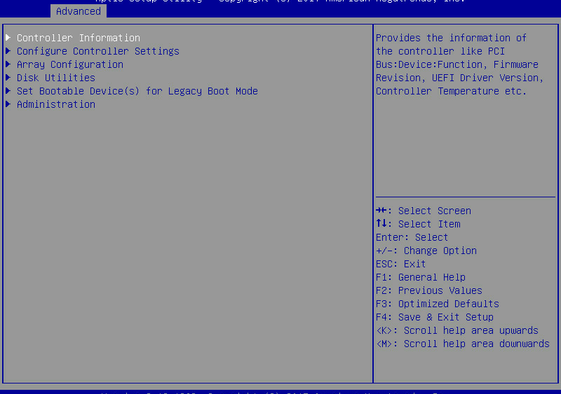
1. On the storage controller configuration screen as shown in Figure 34, select Controller Information and press Enter.
Figure 34 Storage controller configuration screen
2. On the screen as shown in Figure 35, you can see basic information for the storage controller. For more information about the parameter description, see Table 3.
Figure 35 Basic storage controller information screen
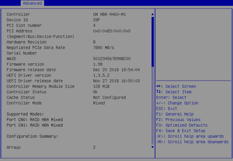
|
Parameter |
Description |
|
Controller |
Storage controller model. |
|
Hardware Revision |
Hardware version. |
Modifying storage controller settings
1. On the storage controller configuration screen as shown in Figure 36, select Configure Controller Settings and press Enter.
Figure 36 Storage controller configuration screen

2. On the screen as shown in Figure 37, select Modify Controller Settings and press Enter.
Figure 37 Configure Controller Settings screen
3. On the screen as shown in Figure 38, modify the basic storage controller settings as needed. If no logical drives are available, you can only modify the operating mode for the storage controller.
Figure 38 Modify Controller Settings screen

Clearing storage controller configuration information
1. On the storage controller configuration screen as shown in Figure 39, select Configure Controller Settings and press Enter.
Figure 39 Storage controller configuration screen

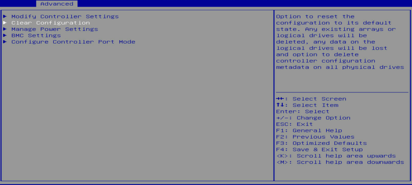
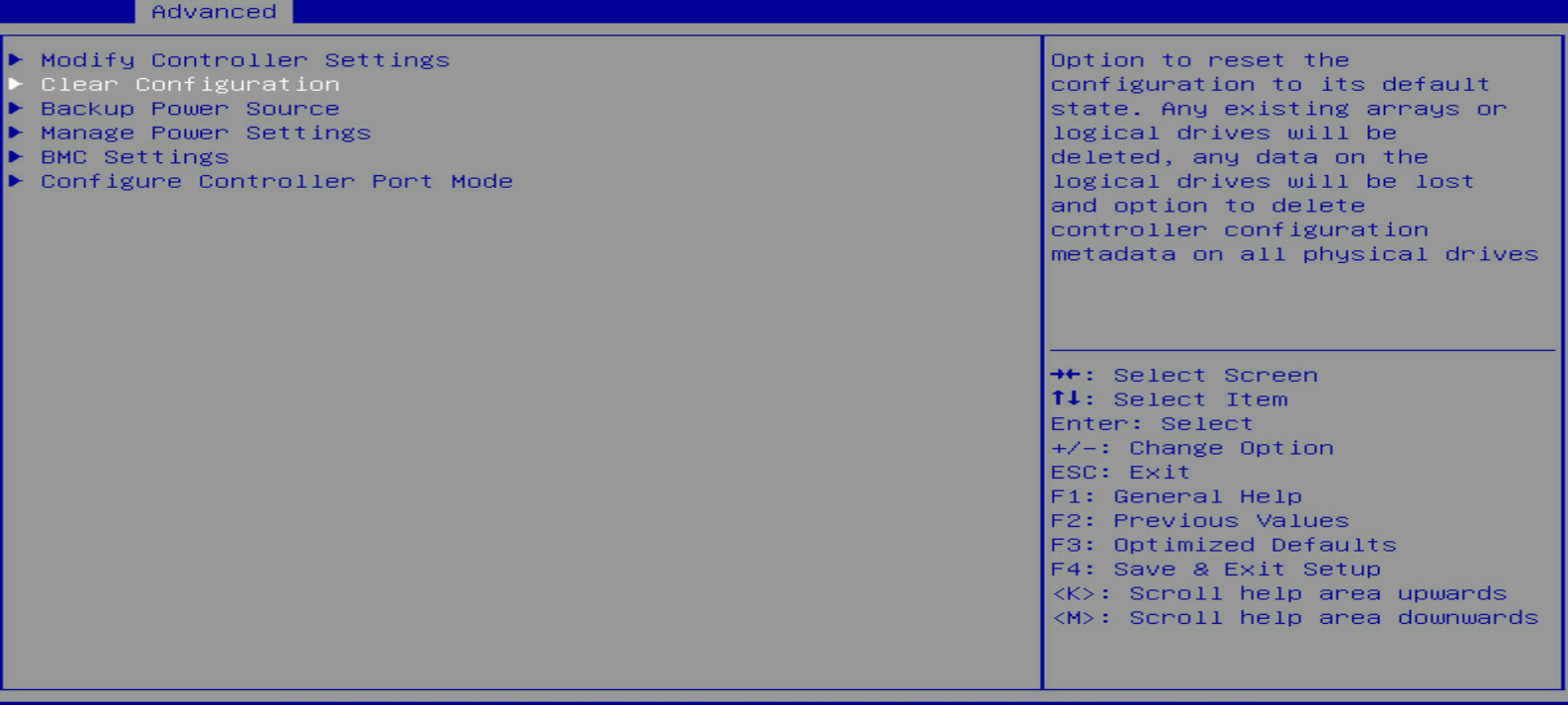
2. On the screen as shown in Figure 40 or Figure 41, select Clear Configuration and press Enter.
Figure 40 Configure Controller Settings screen (for the HBA-H460-M1)
|
|
NOTE: The RAID-P460-M2, RAID-P460-B2, RAID-P460-M4, and RAID-P460-B4 storage controllers support the Backup Power Source option. This option indicates that the controllers can provide power fail safeguard if it has a supercapacitor connected. |
3. On the screen as shown in Figure 42, select Delete All Array Configurations and press Enter.
Figure 42 Selecting Delete All Array Configurations

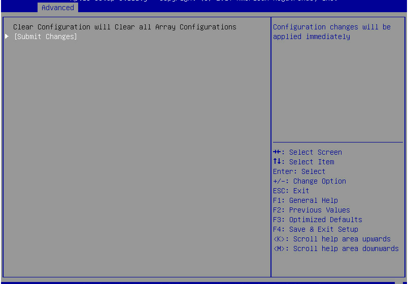
4. On the screen as shown in Figure 43, select Submit Changes and press Enter.
Figure 43 Selecting Submit Changes
Upgrading the storage controller firmware online
The BIOS supports only online firmware upgrade. To upgrade the SEEPROM, contact Technical Support.
To upgrade the storage controller firmware online:
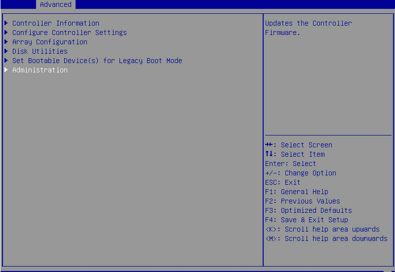
1. On the storage controller configuration screen as shown in Figure 44, select Administration and press Enter.
Figure 44 Storage controller configuration screen
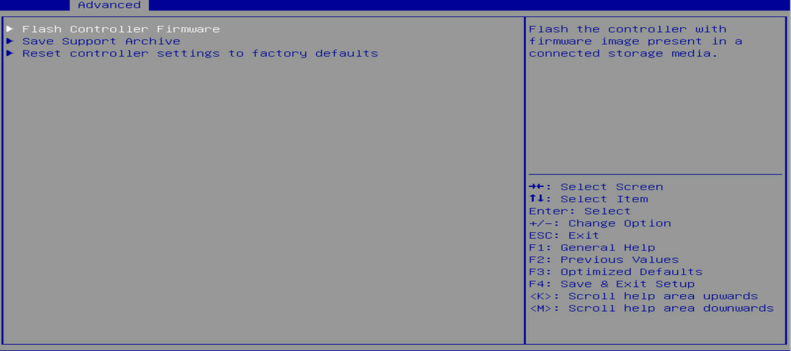
2. On the screen as shown in Figure 45, select Flash Controller Firmware and press Enter.
Figure 45 Administration screen
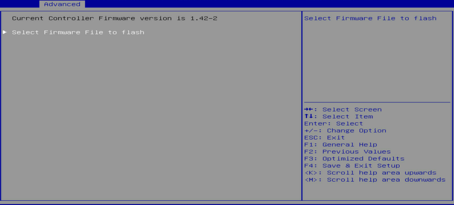
3. On the screen as shown in Figure 46, select Select Firmware File to flash and press Enter.
Figure 46 Selecting Select Firmware File to flash
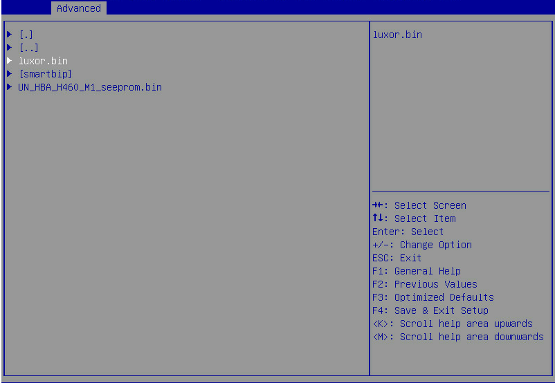
4. On the screen as shown in Figure 47, select the target device where the update file is located and press Enter.
Figure 47 Selecting the target device

5. On the screen as shown in Figure 48, select the update file suffixed with .bin (luxor.bin in this example) and press Enter.
Figure 48 Selecting the update file
6. On the screen as shown in Figure 49, select Flash Controller Firmware and press Enter.
Figure 49 Selecting Flash Controller Firmware
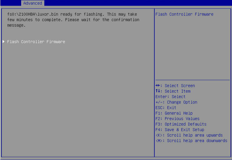
7. After the update is complete, press F4 and select Yes on the dialog box that opens. The update will take effect at next startup.
Configuring RAID arrays in legacy mode
This section describes how to configure RAID arrays through a storage controller in legacy mode. For more information about how to enter the BIOS and set the boot mode to legacy, see the BIOS user guide for the server.
RAID array configuration tasks at a glance
To configure RAID arrays in legacy mode, perform the following tasks:
· Accessing the storage controller configuration screen
· Switching the operating mode
· (Optional.) Configuring hot spare drives
· (Optional.) Configuring the primary boot drive
· (Optional.) Deleting a RAID array
· (Optional.) Viewing drive information
· (Optional.) Locating drives
· (Optional.) Erasing drives
· (Optional.) Modifying storage controller settings
· (Optional.) Displaying backup power source status
· (Optional.) Clearing storage controller configuration
Accessing the storage controller configuration screen
During server POST as shown in Figure 50, press Ctrl+A.
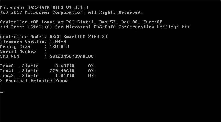
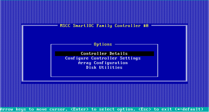
The storage controller configuration screen opens as shown in Figure 51. You can view basic RAID array status and version information on the storage controller configuration screen.
Figure 51 Storage controller configuration screen
Switching the operating mode
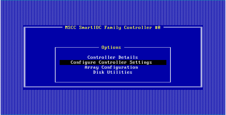
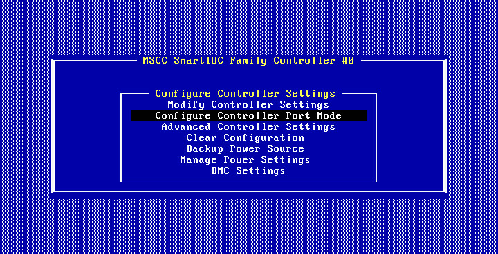
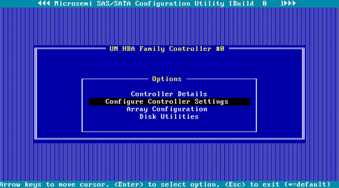
1. On the storage controller configuration screen as shown in Figure 52, select Configure Controller Settings and press Enter.
Figure 52 Storage controller configuration screen
2. On the screen as shown in Figure 53, select Configure Controller Port Mode and press Enter.
Figure 53 Configure Controller Settings screen
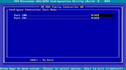
3. On the screen as shown in Figure 54, change the operating mode for Port CN0 or Port CN1 as needed.
Figure 54 Configure Controller Port Mode screen
Configuring a RAID array
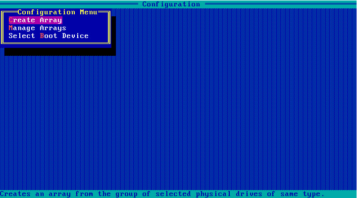
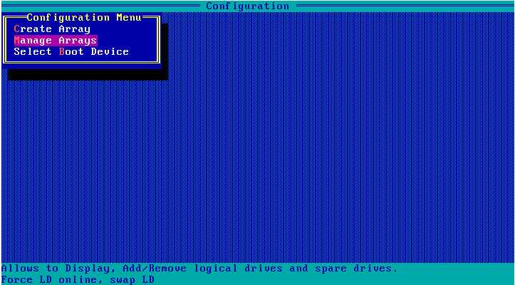
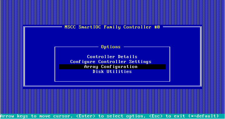
1. On the storage controller configuration screen as shown in Figure 55, select Array Configuration and press Enter.
Figure 55 Storage controller configuration screen
2. On the screen as shown in Figure 56, select Create Array and press Enter.
Figure 56 Array Configuration screen
3. On the screen as shown in Figure 57, navigate to the target drive and press Insert or the space bar to select it. Repeat this step to add more drives, and press Enter.
Figure 57 Selecting the target drive

4. On the screen as shown in Figure 58, set the values for RAID Level, Logical Drive Name, Strip/Full Stripe Size, Parity Group Count, Build Method, Size, and Acceleration Method. Then, select Done and then press Enter. For more information about the parameter description, see Table 4.
Figure 58 Configuring RAID array parameters
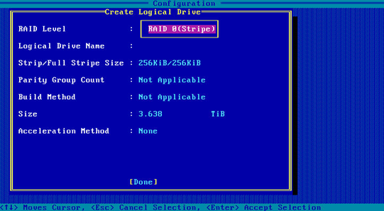
|
Parameter |
Description |
|
RAID Level |
The RAID level determines the drive performance, fault tolerance capability, and logical drive capacity. |
|
Logical Drive Name |
RAID array name. |
|
Strip/Full Stripe Size |
Data block size for each drive. |
|
Parity Group Count |
Number of RAID 1 or RAID 5 groups used to create RAID 10 or RAID 50. |
|
Build Method |
Method used to create the RAID array. |
|
Size |
Capacity for the RAID array. |
|
Acceleration Method |
Logical drive acceleration method. |
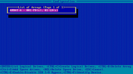
5. On the screen as shown in Figure 59, select Manage Arrays and press Enter.
Figure 59 Selecting Manage Arrays

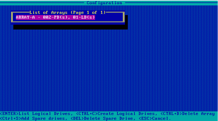
6. On the screen as shown in Figure 60, select the RAID array you want to view and press Enter to view detailed information about the RAID array (including RAID array name, level, and drive information).
Figure 60 Selecting the target RAID array
Configuring hot spare drives
Restrictions and guidelines
In legacy mode, if a hot spare drive is configured for a RAID array, the hot spare drive will not take effect on other RAID arrays. To avoid this problem, configure all RAID arrays and then add hot spare drives.
Procedure
1. On the storage controller configuration screen as shown in Figure 61, select Array Configuration and press Enter.
Figure 61 Storage controller configuration screen

2. On the screen as shown in Figure 62, select Manage Arrays and press Enter.
Figure 62 Array Configuration screen
3. On the screen as shown in Figure 63, select the target array and press Ctrl+S.
Figure 63 Selecting the target array

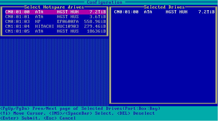
4. On the screen as shown in Figure 64, navigate to the target drive and press Insert or the space bar to select it. Repeat this step to add more drives, and press Enter.
Figure 64 Selecting the target drives
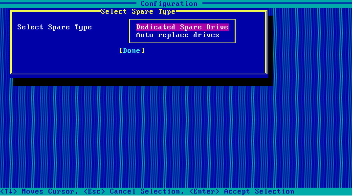
5. On the screen as shown in Figure 65, select the spare type, select Done, and then press Enter.
Figure 65 Selecting the spare type
Configuring the primary boot drive
Configuring a physical drive as the primary boot drive
1. On the storage controller configuration screen as shown in Figure 66, select Array Configuration and press Enter.
Figure 66 Storage controller configuration screen
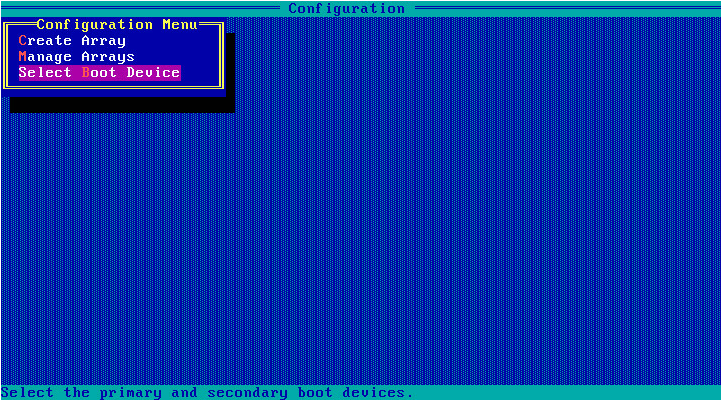
2. On the screen as shown in Figure 67, select Select Boot Device and press Enter.
Figure 67 Array Configuration screen
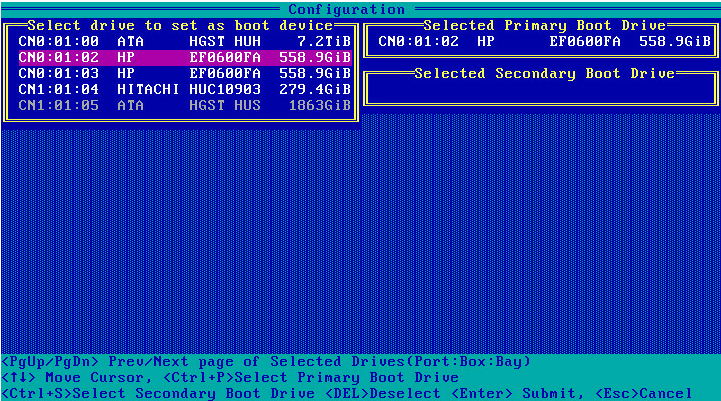
3. On the screen as shown in Figure 68, select the target drive, press Ctrl+P, and then press Enter.
Figure 68 Selecting the target drive
Configuring a logical drive as the primary boot drive
1. On the storage controller configuration screen, select Array Configuration and press Enter.
2. On the screen as shown in Figure 69, select Manage Arrays and press Enter.
Figure 69 Array Configuration screen

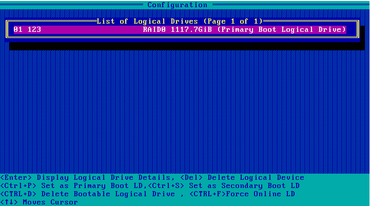
3. On the screen as shown in Figure 70, select the target RAID array and press Enter.
Figure 70 Selecting the target RAID array
4. On the screen as shown in Figure 71, press Ctrl+P to configure the RAID array as the primary boot drive.
Figure 71 Configuring the primary boot drive
Deleting a RAID array
1. On the storage controller configuration screen as shown in Figure 72, select Array Configuration and press Enter.
Figure 72 Storage controller configuration screen

2. On the screen as shown in Figure 73, select Manage Arrays and press Enter.
Figure 73 Array Configuration screen

3. On the screen as shown in Figure 74, select the target array, press Enter, and then press Delete to delete the array.
Figure 74 Deleting the target array

Viewing drive information
1. On the storage controller configuration screen as shown in Figure 75, select Disk Utilities and press Enter.
Figure 75 Storage controller configuration screen
2. On the screen as shown in Figure 76, you can see information about all available drives.
Locating drives
1. Select the target drive on the screen as shown in Figure 76 and press Enter.
2. On the screen as shown in Figure 77, select Identify Drive and press Enter. The Fault/UID LED on the drive turns steady blue.
Figure 77 Identifying the device
Erasing drives
Procedure
1. On the storage controller configuration screen as shown in Figure 76, select the drive to be erased, and then press Enter.
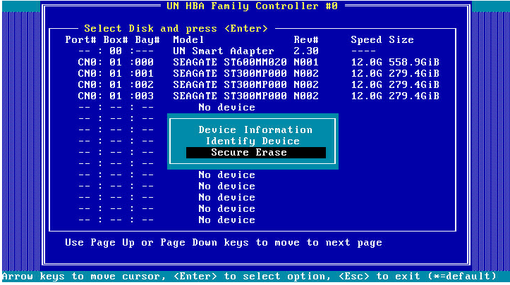
2. On the screen as shown in Figure 78, select Secure Erase and then press Enter.
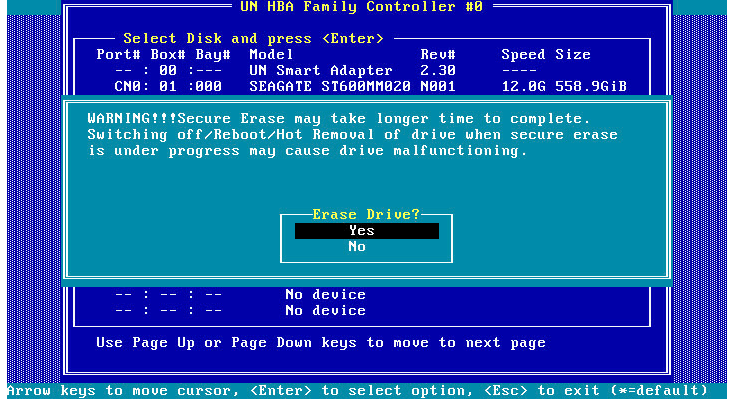
3. On the screen as shown in Figure 79, select Yes, and press Enter.
Figure 79 Confirming the operation
Modifying storage controller settings
1. On the storage controller configuration screen as shown in Figure 80, select Configure Controller Settings and press Enter.
Figure 80 Storage controller configuration screen

2. On the screen as shown in Figure 81, select Modify Controller Settings and press Enter.
Figure 81 Configure Controller Settings screen

3. On the screen as shown in Figure 82, you can view the storage controller settings.
Figure 82 Modify Controller Settings screen
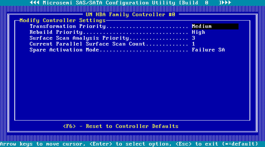
4. Press F6 to restore the storage controller settings to the default.
|
|
NOTE: The settings (such as Transformation Priority and Rebuild Priority) on the screen as shown in Figure 82 are configurable, but the default values are typically used. |
Displaying backup power source status
This feature is available only when a RAID-P460-M2, RAID-P460-B2, RAID-P460-M4, or RAID-P460-B4 controller is installed. You can perform this task to view the status of the installed backup power source, if any.
To display backup power source status:
1. On the storage controller configuration screen as shown in Figure 83, select Configure Controller Settings and press Enter.
Figure 83 Storage controller configuration screen

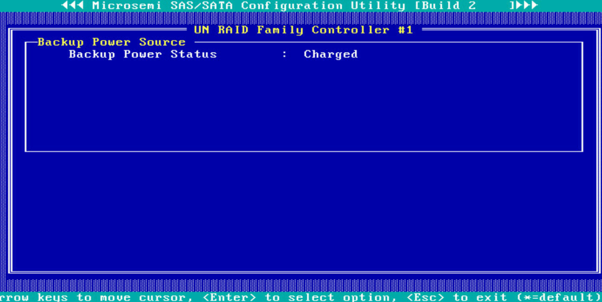
2. On the screen as shown in Figure 84, select Backup Power Source and press Enter.
Figure 84 Backup Power Source screen
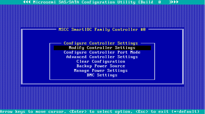
Figure 85 Backup Power Source screen
|
|
NOTE: For an HBA-H460-M1 or HBA-H460-B1 storage controller, the Backup Power Status field is fixed to Not Present. |
Clearing storage controller configuration
1. On the storage controller configuration screen as shown in Figure 86, select Configure Controller Settings and press Enter.
Figure 86 Storage controller configuration screen

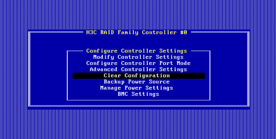
2. On the screen as shown in Figure 87, select Clear Configuration and press Enter.
Figure 87 Configure Controller Settings screen
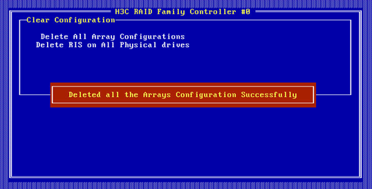
3. On the screen as shown in Figure 88, select Delete All Array Configurations and press Enter. In the confirmation dialog box that opens, select Yes and press Enter.
Figure 88 Clearing storage controller configuration
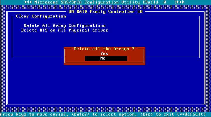
The screen as shown in Figure 89 opens, indicating that the clearing operation is complete.