- Table of Contents
-
- H3C Servers Storage Controller User Guide-6W107
- 00-Preface
- 01-Storage controller overview
- 02-Storage controller features
- 03-Configuring an embedded RSTe RAID controller
- 04-Configuring an NVMe VROC module
- 05-Configuring a P430 storage controller
- 06-Configuring a 1000 storage controller
- 07-Configuring a 9361, 9440, 9460, L460, P5408, or H5408 storage controller
- 08-Configuring an H460, P460, P240 or P4408 storage controller
- 09-Configuring a 9300 storage controller
- 10-Configuring a 9311 storage controller
- 11-Configuring an LSI 9400 or 9500 series storage controller
- 12-Configuring a RAID-MARVELL-SANTACRUZ-LP-2i storage controller
- 13-Appendix A Troubleshooting storage controllers
- 14-Appendix B RAID arrays and fault tolerance
- Related Documents
-
07-Configuring a 9361, 9440, 9460, L460, P5408, or H5408 storage controller
Configuring an LSI-9440, 9460, 5408, LSI-9361, L460, 9560, or 9540 series storage controller
About LSI-9440, 9460, 5408, LSI-9361, L460, 9560, or 9540 series storage controllers
The storage controllers provide a maximum interface rate of 12 Gbps, and some storage controllers support caching, which greatly increases performance and data security. For more information about storage controller details and the supported cache, contact Technical Support.
This chapter is applicable to the following storage controllers:
· RAID-LSI-9361-8i(1G)-A1-X
· RAID-LSI-9361-8i(2G)-1-X
· HBA-LSI-9440-8i
· RAID-LSI-9460-8i(2G)
· RAID-LSI-9460-8i(4G)
· RAID-LSI-9460-16i(4G)
· RAID-L460-M4
· HBA-H5408-Mf-8i
· RAID-P5408-Mf-8i-4GB
· RAID-P5408-Ma-8i-4GB
· RAID-LSI-9560-LP-16i-8GB
· RAID-LSI-9560-LP-8i-4GB
· HBA-LSI-9540-LP-8i
Features
RAID levels
The supported RAID levels vary by storage controller model. For more information about the supported RAID levels of each storage controller, see H3C Servers Storage Controllers Technical Specifications.
Table 1 shows the minimum number of drives required by each RAID level and the maximum number of failed drives supported by each RAID level. For more information about RAID levels, see "Appendix B RAID arrays and fault tolerance."
Table 1 RAID levels and the numbers of drives for each RAID level
|
RAID level |
Min. drives required |
Max. failed drives |
|
RAID 0 |
1 |
0 |
|
RAID 1 |
2 |
1 |
|
RAID 5 |
3 |
1 |
|
RAID 6 |
3 (4 is recommended.) |
2 |
|
RAID 10 |
4 |
n, where n is the number of RAID 1 arrays in the RAID 10 array. NOTE: Storage controllers described in this chapter support a maximum of eight member RAID 1 arrays. |
|
RAID 50 |
6 |
n, where n is the number of RAID 5 arrays in the RAID 50 array. |
|
RAID 60 |
6 (8 is recommended.) |
2n, where n is the number of RAID 6 arrays in the RAID 60 array. |
Restrictions and guidelines for configuring RAID
· As a best practice, configure RAID with drives that do not contain RAID information.
· To build a RAID successfully and ensure RAID performance, make sure all drives in the RAID are the same type (HDDs or SSDs) and have the same connector type (SAS or SATA).
· For efficient use of storage, use drives that have the same capacity to build a RAID. If the drives have different capacities, the lowest capacity is used across all drives in the RAID.
· If you use one physical drive to create multiple RAIDs, RAID performance might decrease in addition to increased maintenance complexities.
Configuring RAID arrays in UEFI mode
This section describes how to configure RAID arrays through a storage controller in UEFI mode. For more information about how to enter the BIOS and set the boot mode to UEFI, see the BIOS user guide for the server.
RAID array configuration tasks at a glance
To configure a RAID array in UEFI mode, perform the following tasks:
· Accessing the storage controller configuration screen
· (Optional.) Configuring hot spare drives
· (Optional.) Deleting a RAID array
· (Optional.) Locating drives
· (Optional.) Initializing a virtual drive
· (Optional.) Initializing a physical drive
· (Optional.) Erasing drives
· (Optional.) Expanding a RAID array
· (Optional.) Migrating the RAID level
· (Optional.) Clearing RAID array information on the drive
· (Optional.) Hiding a virtual drive
· (Optional.) Hiding a RAID array
· (Optional.) Upgrading the storage controller firmware online
Accessing the storage controller configuration screen
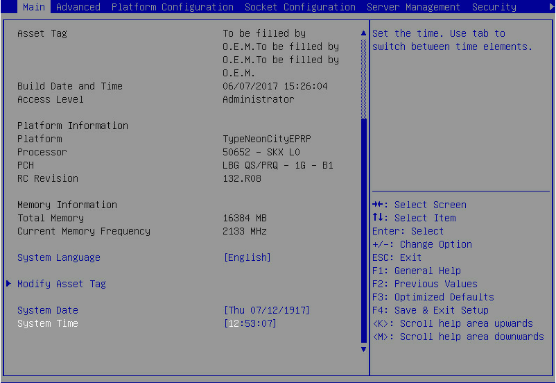
1. Access the BIOS. Press Delete, Esc, or F2 as prompted during server POST to open the BIOS setup screen as shown in Figure 1. For some devices, the Front Page screen opens, and you must select Device Management before proceeding to the next step.
For how to navigate screens and modify settings, see the operation instructions at the lower right corner.
Figure 1 BIOS setup screen
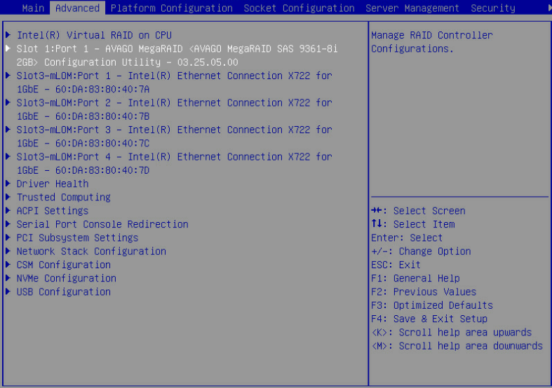
2. On the screen as shown in Figure 2, select Advanced > storage controller model, and press Enter.
In this example, the storage controller model is AVAGO MegaRAID <AVAGO MegaRAID SAS 9361-8i>.
Figure 2 Advanced screen
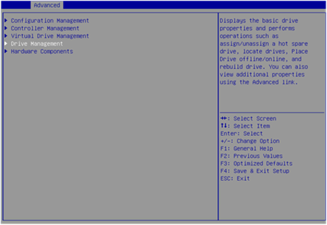
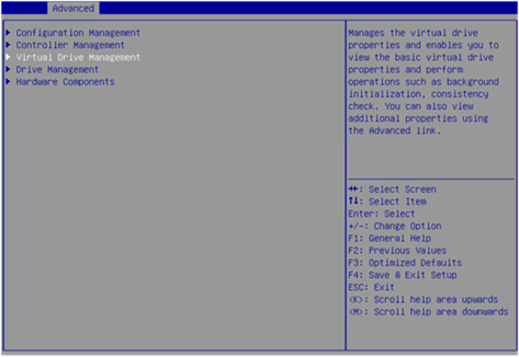
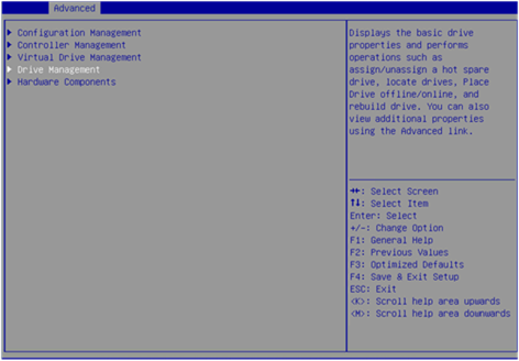
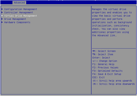
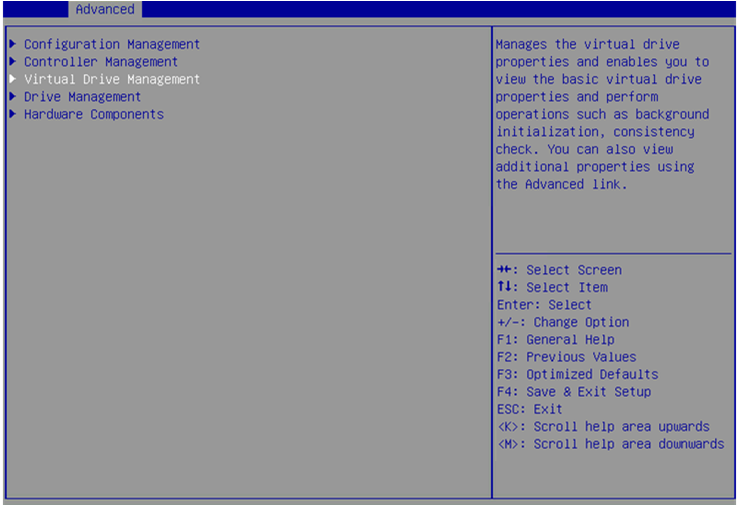
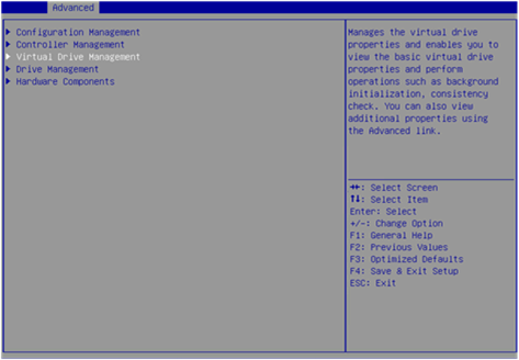
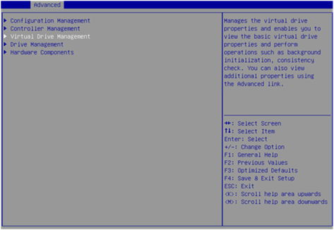
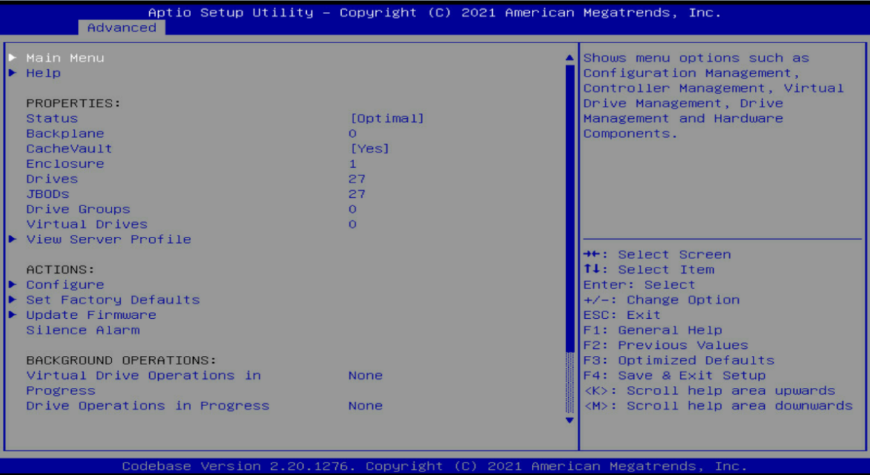
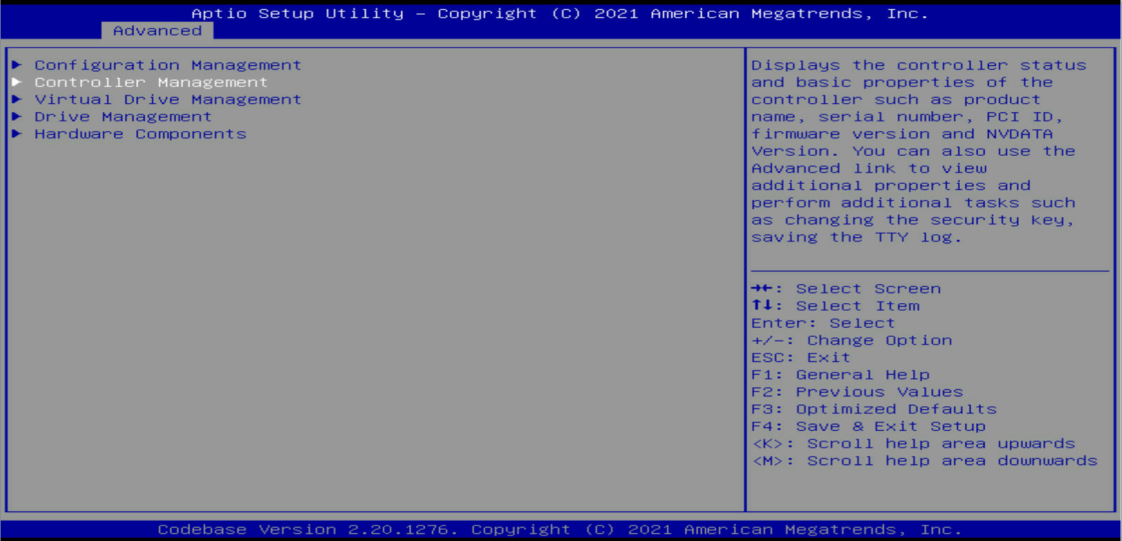
3. Select Main Menu as shown in Figure 3, and press Enter.
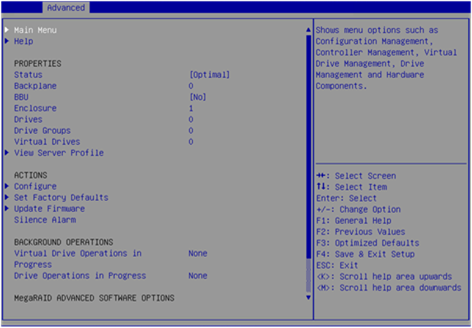
The storage controller configuration screen as shown in Figure 4 opens. This screen contains five tasks as described in Table 2.
Figure 4 Storage controller configuration screen

Table 2 Storage controller configuration tasks
|
Option |
Description |
|
Configuration Management |
Select Configuration Management to perform the following tasks: · Create RAID arrays. · View RAID array properties. · View hot spare drives. · Clear configuration. |
|
Controller Management |
Select Controller Management to perform the following tasks: · View and manage controller properties. · Clear, schedule, or run controller events. |
|
Virtual Drive Management |
Select Virtual Drive Management to perform the following tasks: · View logical drive properties. · Locate logical drives. · Run consistency check. |
|
Drive Management |
Select Drive Management to perform the following tasks: · View physical drive properties. · Locate drives. · Initialize drives. · Rebuild drives. |
|
Hardware Components |
Select Hardware Components to perform the following tasks: · View supercapacitor properties. · Manage supercapacitor. · Manage peripheral components. |
Switching the drive state
The storage controller supports the following drive states:
· Unconfigured Good—The drive is normal and can be used for RAID array or hot backup configuration.
· Unconfigured Bad—The drive is faulty or has RAID array information remaining on it. If the drive is faulty, replace the drive. If RAID array information remains on the drive, clear the RAID array information.
· Hotspare—The drive is a hot spare drive.
· JBOD/JBOD online—Just a Bunch Of Disks. The drive is a passthrough or passthrough-like drive and does not support RAID configuration. The passthrough drive is in JBOD online state by default for the RAID-LSI-9560-LP-16i-8GB storage controller and in JBOD state for other storage controllers.
To switch from Unconfigured Good state to Unconfigured Bad state:
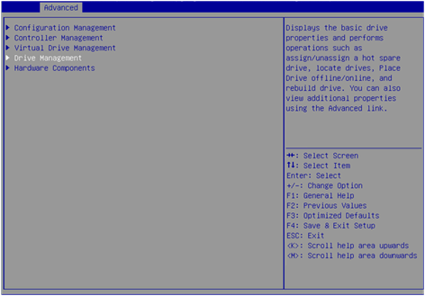
1. On the storage controller configuration screen as shown in Figure 5, select Drive Management and press Enter.
Figure 5 Storage controller configuration screen
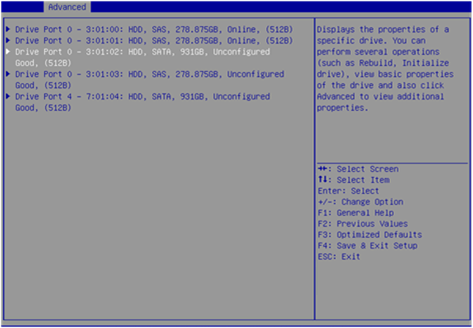
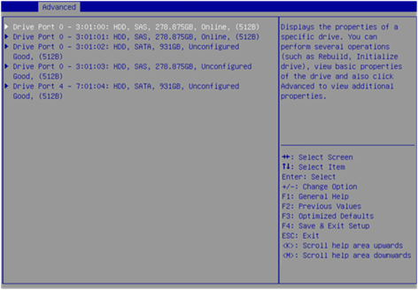
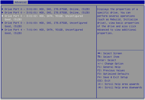
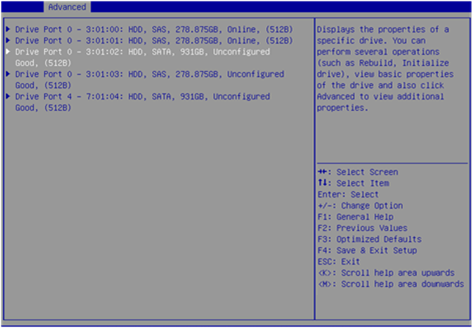
2. On the screen as shown in Figure 6, select the target drive and press Enter.
Figure 6 Drive Management screen
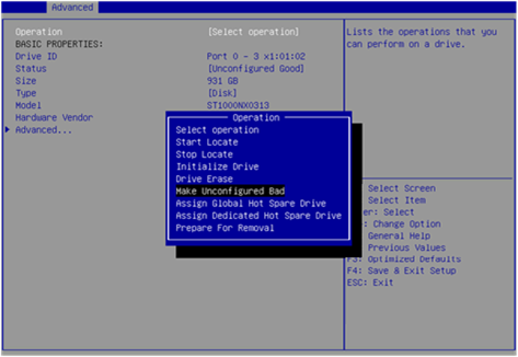
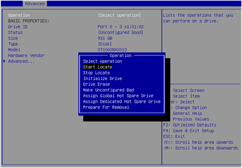
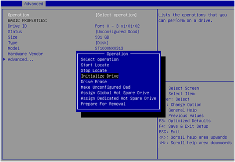
3. On the screen as shown in Figure 7, select Operation and press Enter. On the dialog box that appears, select Make Unconfigured Bad and press Enter.
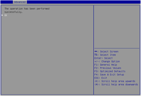
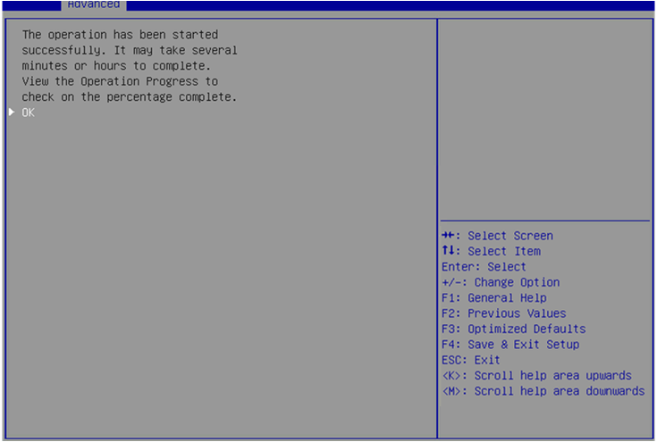
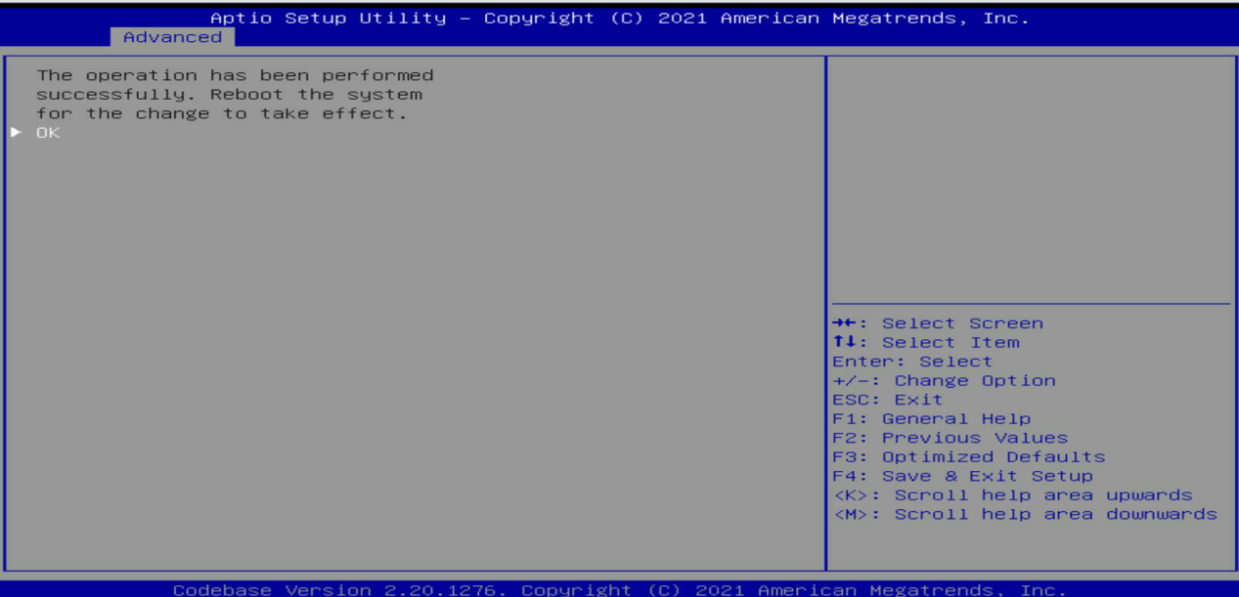
4. On the screen as shown in Figure 8, select Go and press Enter.
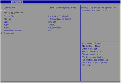
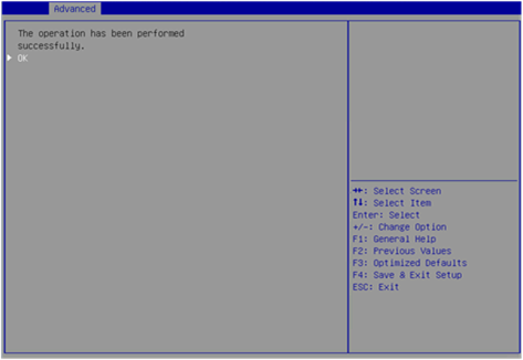
When the operation is complete, the screen as shown in Figure 9 opens.
Figure 9 Completing drive state switchover
Configuring a RAID array
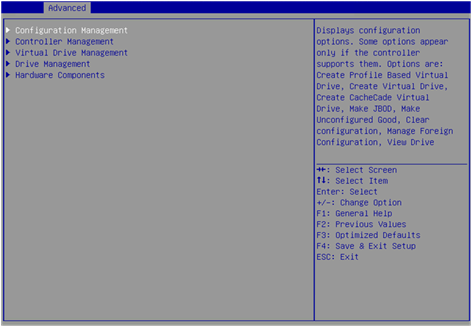
1. On the storage controller configuration screen as shown in Figure 10, select Configuration Management and press Enter.
Figure 10 Storage controller configuration screen
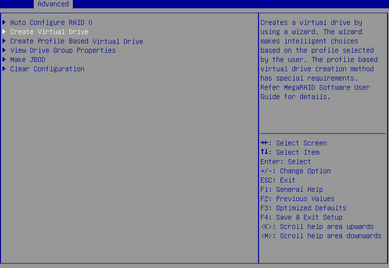
2. On the screen as shown in Figure 11, select Create Virtual Drive and press Enter.
Figure 11 Selecting Create Virtual Drive
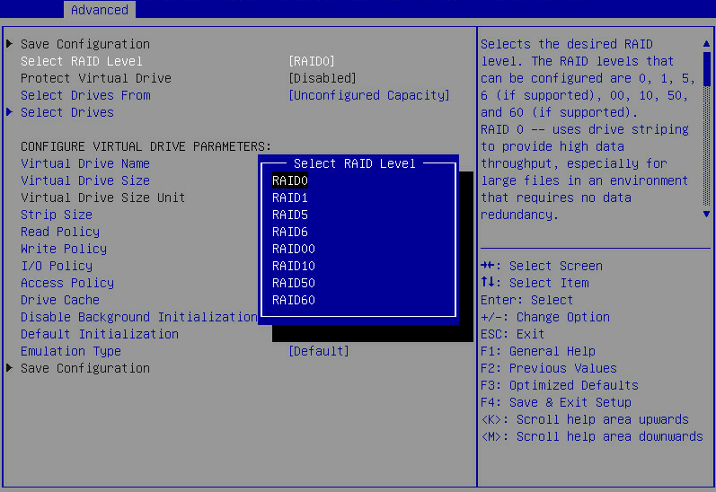
3. On the screen as shown in Figure 12, select Select RAID Level to set the RAID level, and then press Enter.
Figure 12 Setting the RAID level
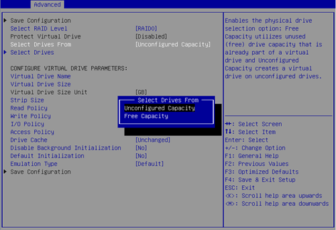
4. On the screen as shown in Figure 13, select Select Drives From to set the drive capacity source, and then press Enter.
¡ Unconfigured Capacity—The capacity source is the unconfigured drives.
¡ Free Capacity—The capacity source is the remaining drive capacity.
Figure 13 Setting the drive capacity source
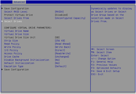
5. On the screen as shown in Figure 14, select Select Drives and press Enter.
Figure 14 Selecting Select Drives
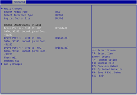
6. On the screen as shown in Figure 15, select the target drives. ([Enabled] following a drive means that the drive has been selected.) Then, select Apply Changes and press Enter. A drive in JBOD or Unconfigured Bad status cannot be selected.
Figure 15 Selecting the target drives
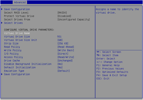
7. On the screen as shown in Figure 16, configure the parameters, select Save Configuration, and press Enter. For more information about the parameter description, see Table 3.
Figure 16 Configuring RAID parameters
|
Parameter |
Description |
|
Virtual Drive Name |
RAID array name, a case-insensitive string of letters, digits, and underscores (_). |
|
Virtual Drive Size |
Capacity for the RAID array. |
|
Virtual Drive Size Unit |
Capacity unit for the RAID array. |
|
Stripe Size |
Data block size for each drive. |
|
Read Policy |
Read cache policy: · Read Ahead—Enables read ahead capability. When this capability is enabled, the storage controller can pre-read sequential data or anticipate data to be requested and store the data in the cache · No Read Ahead—Disables read ahead capability. Compared with the setting of the No Read Ahead, Write Through, and Direct values, setting the Read Ahead, Write Back, and Cached values can improve performance, but at the cost of losing data consistency. |
|
Write Policy |
Write cache policy: · Write Through—Enables the controller to send a data transfer completion signal to the host when the drive subsystem has received all data in a transaction. · Always Write Back—Uses the Write back policy even if the supercapacitor of the storage controller is absent or faulty. If the server is powered off, the controller cache loses its data because of lack of power.. · Write Back—Enables the controller to send a data transfer completion signal to the host when the controller cache receives all data in a transaction. If the supercapacitor is faulty, the Write through policy is used. |
|
Access Policy |
Read and write policy: · Read/Write · Read Only · Blocked |
|
I/O Policy |
I/O policy: · Direct—Enables the system to read or write data directly from or into a drive by read operations (excluding read ahead operations) or by write through operations of the storage controller. · Cached—Enables the cache module to process all read and write operations of the storage controller. Recommended only when CacheCade 1.1 is configured. |
|
Drive Cache |
Drive cache policy: · Enable—Enables the controller to write data in the cache of physical drives during the write process to improve write performance. If this policy is used without a protection method in place, data will get lost upon an unexpected power failure. · Disable—Disables the controller from writing data in the cache of physical drives during the write process. If this policy is used, data will not get lost upon an unexpected power failure, but the write performance will not as high as when drive caching is enabled. · Unchanged—Uses the default drive cache policy. |
|
Disable Background Initialization |
Enabling status of background initialization. |
|
Default Initialization |
Default initialization mode: · NO. · Fast. · Full. |
|
Emulation Type |
Sector size reported to the OS: · Default—Displays 512e (4K) as the sector size as long as one 512e member drive exists, and displays 512n as the sector size if no 512e member drive exists. · Disable—Displays 512n as the sector size if no 512e member drive exists. · Force—Displays 512e (4K) as the sector size even if no 512e member drive exists. |
|
Save Configuration |
Select this option to save the configuration. |
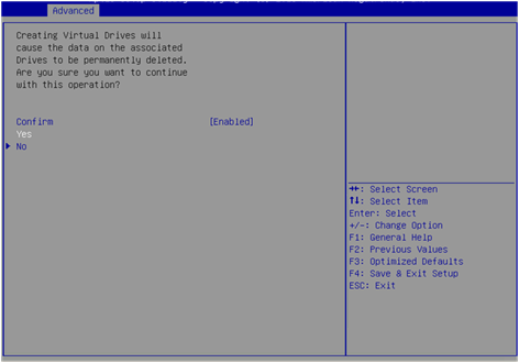
8. On the screen as shown in Figure 17, select Confirm and press Enter. On the dialog box that opens, select Enabled and press Enter. Then, select Yes and press Enter.
Figure 17 Confirming the configuration
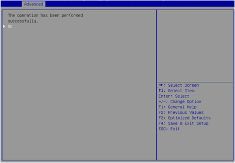
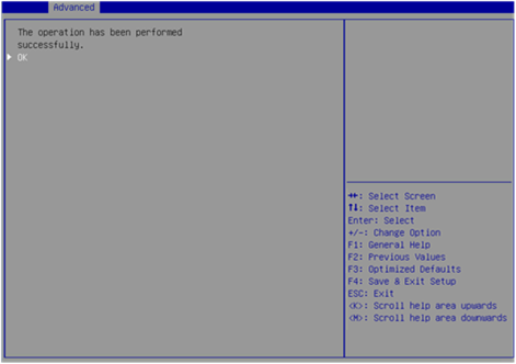
9. On the screen as shown in Figure 18, select OK to return to the storage controller configuration screen.
Figure 18 Completing RAID array configuration
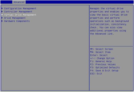
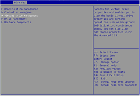
10. Select Virtual Drive Management and press Enter as shown in Figure 19.
Figure 19 Storage controller configuration screen
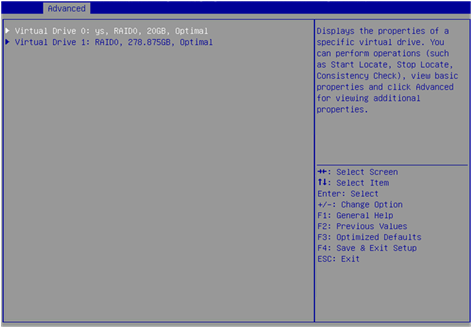
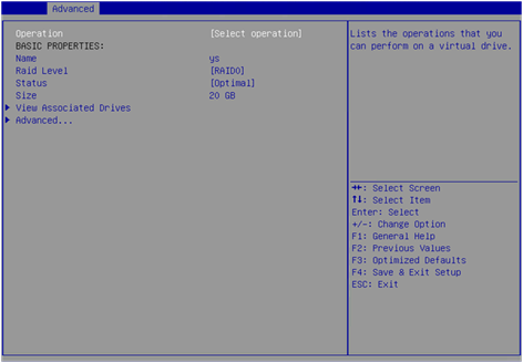
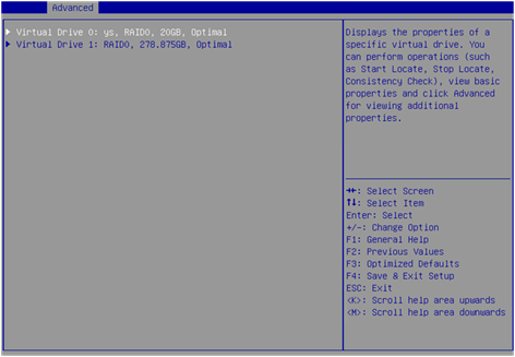
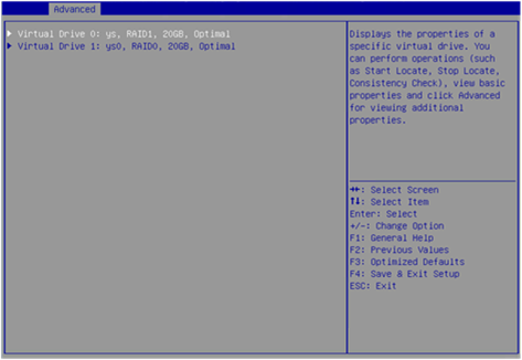
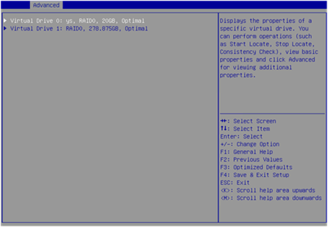
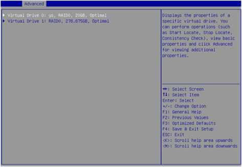
11. On the screen as shown in Figure 20, you can see the created drives. Select the drive you want to view and press Enter.
Figure 20 Virtual Drive Management screen
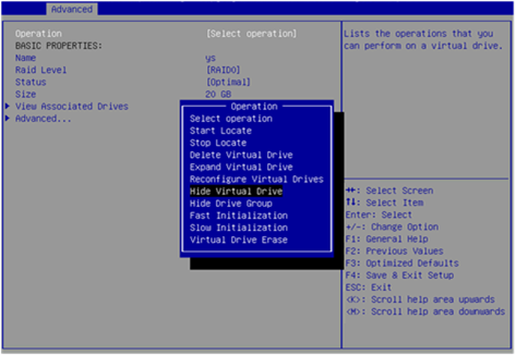
12. On the screen as shown in Figure 21, select View Associated Drives and press Enter. You can view the detailed information about the RAID array, including name, level, and drive information.
Figure 21 Selecting View Associated Drives
Configuring hot spare drives
For data security purposes, configure hot spare drives after configuring a RAID array. You can configure global hot spare drives or dedicated hot spare drives.
|
|
NOTE: · A hot spare drive can be used only for RAID levels with redundancy. · The capacity of a hot spare drive must be equal to or greater than the capacity of the smallest drive in the RAID array. · Only the drive in Unconfigured Good state can be configured as a hot spare drive. |
Configuring a global hot spare drive
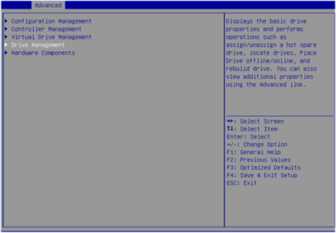
1. On the storage controller configuration screen as shown in Figure 22, select Drive Management and press Enter.
Figure 22 Storage controller configuration screen

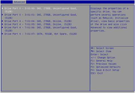
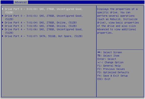
2. On the screen as shown in Figure 23, select the target drive and press Enter.
Figure 23 Drive Management screen
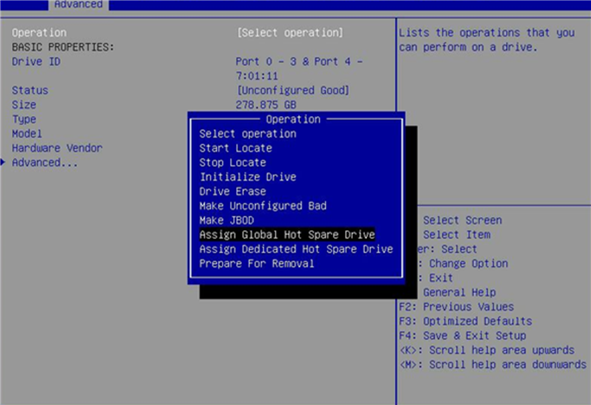
3. On the screen as shown in Figure 24, select Operation and press Enter. On the dialog box that appears, select Assign Global Hot Spare Drive and press Enter.
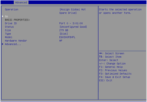
4. On the screen as shown in Figure 25, select Go and press Enter.
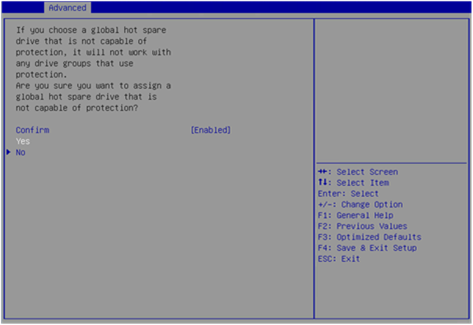
5. On the screen as shown in Figure 26, select Confirm and press Enter. On the dialog box that opens, select Enabled and press Enter. Then, select Yes and press Enter.
Figure 26 Confirming the configuration
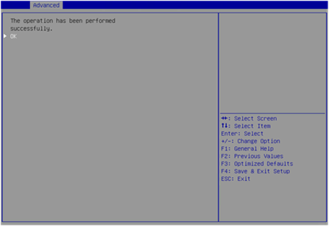
When the operation is complete, the screen as shown in Figure 27 opens.
Figure 27 Completing global hot spare drive configuration
Configuring a dedicated hot spare drive
1. On the storage controller configuration screen as shown in Figure 28, select Drive Management and press Enter.
Figure 28 Storage controller configuration screen
2. On the screen as shown in Figure 29, select the target drive and press Enter.
Figure 29 Drive Management screen
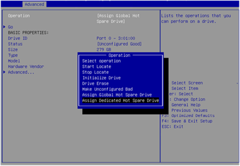
3. On the screen as shown in Figure 30, select Operation and press Enter. On the dialog box that appears, select Assign Dedicated Hot Spare Drive and press Enter.
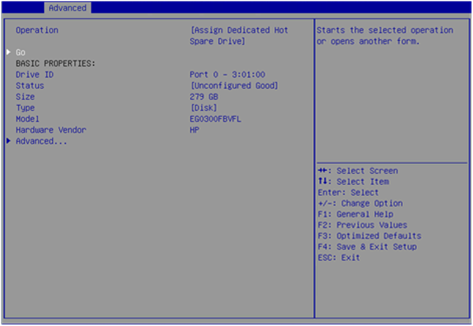
4. On the screen as shown in Figure 31, select Go and press Enter.
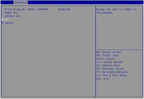
5. On the screen as shown in Figure 32, select the drive you want to configure as the hot spare drive. ([Enabled] following the drive means that the drive has been selected.) Then, select OK and press Enter.
Figure 32 Confirming selection
When the operation is complete, the screen as shown in Figure 33 opens.
Figure 33 Completing the operation

Deleting a RAID array
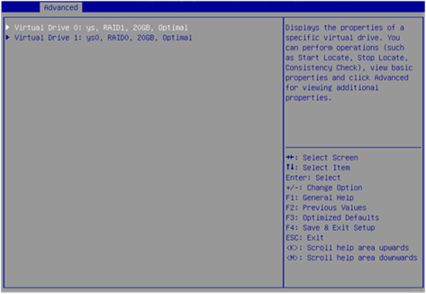
1. On the storage controller configuration screen as shown in Figure 34, select Virtual Drive Management and press Enter.
Figure 34 Storage controller configuration screen
2. On the screen as shown in Figure 35, select the target virtual drive and press Enter.
Figure 35 Virtual Drive Management screen
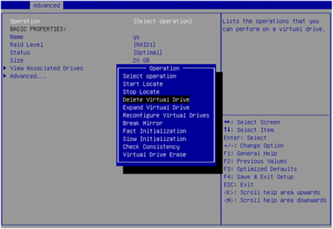
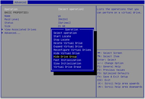
3. On the screen as shown in Figure 36, select Operation and press Enter. On the dialog box that appears, select Delete Virtual Drive and press Enter.
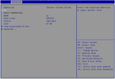
4. On the screen as shown in Figure 37, select Go and press Enter.
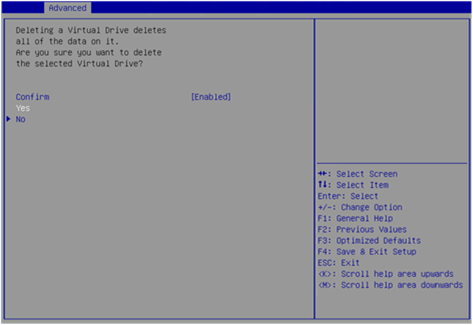
5. On the screen as shown in Figure 38, select Confirm and press Enter. On the dialog box that opens, select Enabled and press Enter. Then, select Yes and press Enter.
Figure 38 Confirming the deletion
When the operation is complete, the screen as shown in Figure 39 opens.
Figure 39 Completing the operation
Locating drives
This task allows you to locate a physical drive or all drives for a virtual drive.
Locating a physical drive
1. On the storage controller configuration screen as shown in Figure 40, select Drive Management and press Enter.
Figure 40 Storage controller configuration screen
2. On the screen as shown in Figure 41, select the target drive and press Enter.
Figure 41 Selecting the target drive
3. On the screen as shown in Figure 42, select Operation and press Enter. On the dialog box that opens, select Start Locate and press Enter.
4. On the screen as shown in Figure 43, select Go and press Enter.
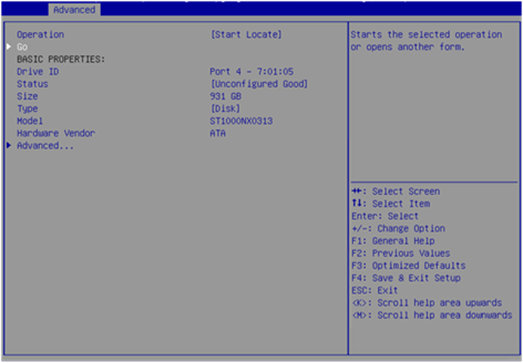
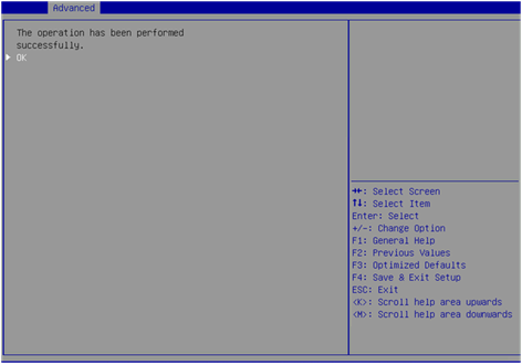
When the operation is complete, the screen as shown in Figure 44 opens. The Fault/UID LED on the drive turns steady blue.
Figure 44 Completing locating the physical drive
Locating all drives for a virtual drive
1. On the storage controller configuration screen as shown in Figure 45, select Virtual Drive Management and press Enter.
Figure 45 Storage controller configuration screen
2. On the screen as shown in Figure 46, select the target drive and press Enter.
Figure 46 Selecting the target drive
3. On the screen as shown in Figure 47, select Operation and press Enter. On the dialog box that opens, select Start Locate and press Enter.
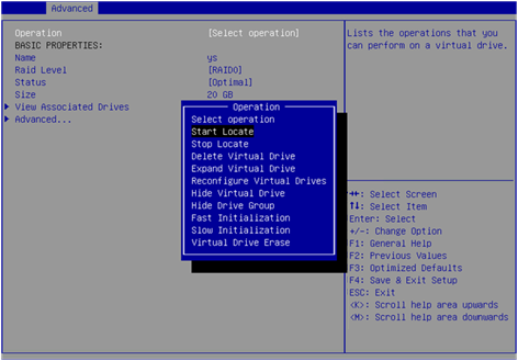
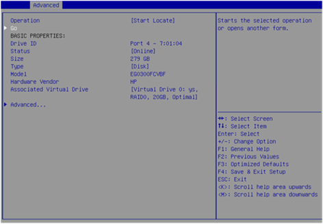
4. On the screen as shown in Figure 48, select Go and press Enter.
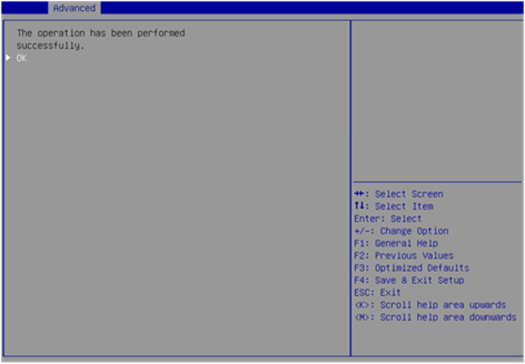
When the operation is complete, the screen as shown in Figure 49 opens. The Fault/UID LED on the drive turns steady blue.
Figure 49 Completing locating all drives for a virtual drive
Initializing a virtual drive
This task allows you to initialize a virtual drive to be used by operating systems.
To initialize a virtual drive:
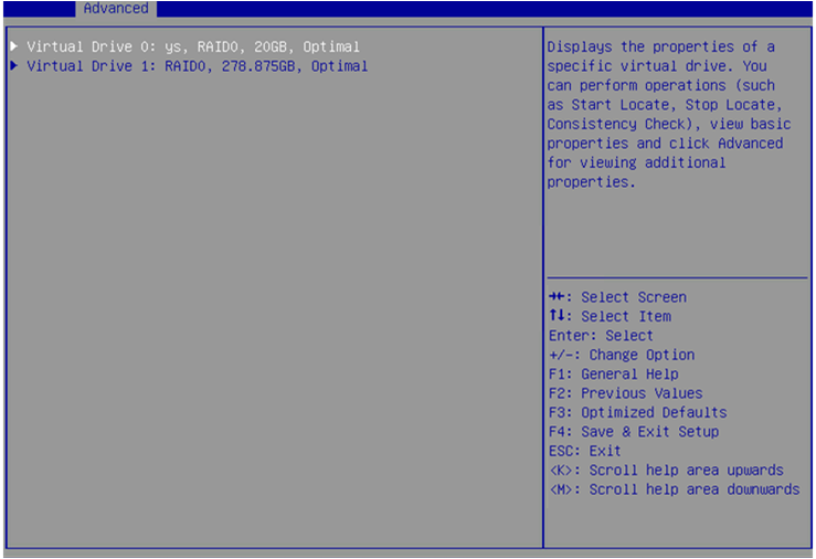
1. On the storage controller configuration screen as shown in Figure 50, select Virtual Drive Management and press Enter.
Figure 50 Storage controller configuration screen
2. On the screen as shown in Figure 51, select the target drive and press Enter.
Figure 51 Virtual Drive Management screen
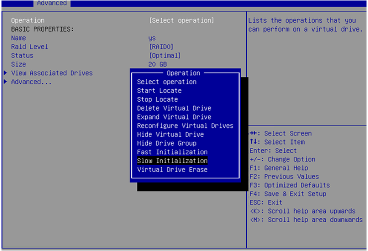
3. On the screen as shown in Figure 52, select Operation and press Enter. On the dialog box that appears, select Fast Initialization or Slow Initialization and press Enter.
|
|
NOTE: Fast initialization allows immediately writing data. Slow initialization allows writing data after initialization is complete. |
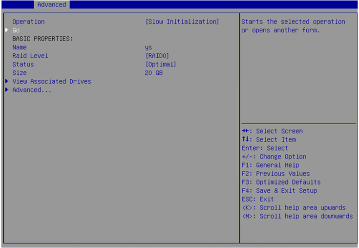
4. On the screen as shown in Figure 53, select Go and press Enter.
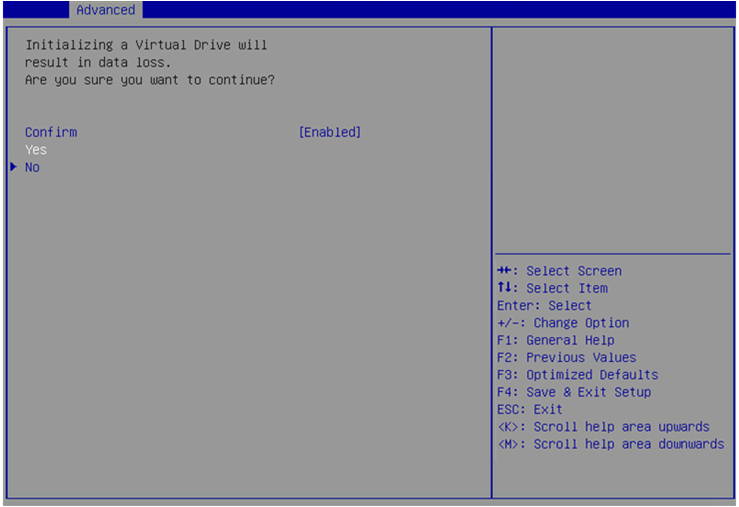
5. On the screen as shown in Figure 54, select Confirm and press Enter. On the dialog box that opens, select Enabled and press Enter. Then, select Yes and press Enter.
Figure 54 Confirming the initialization
When the operation is complete, the screen as shown in Figure 55 opens.
Figure 55 Completing the operation
Initializing a physical drive
1. On the storage controller configuration screen as shown in Figure 56, select Drive Management and press Enter.
Figure 56 Storage controller configuration screen
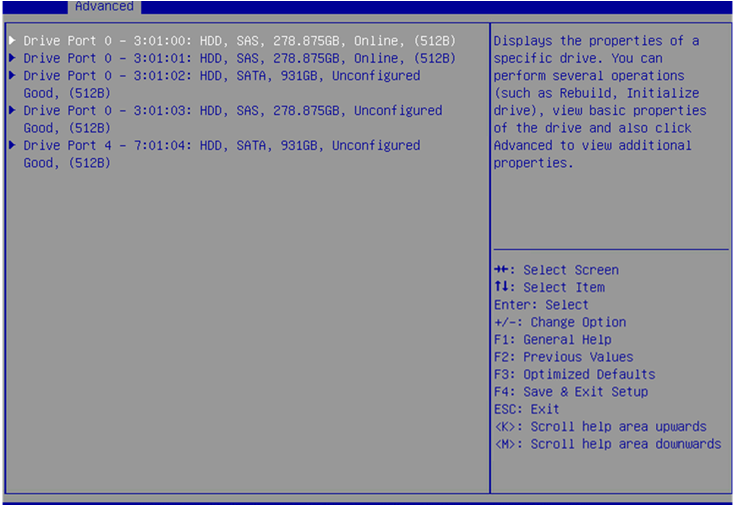
2. On the screen as shown in Figure 57, select the target drive and press Enter.
Figure 57 Drive Management screen
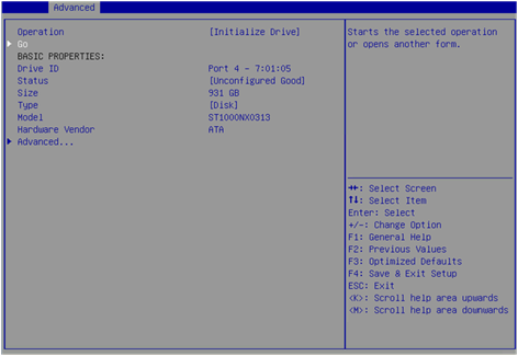
3. On the screen as shown in Figure 58, select Operation and press Enter. On the dialog box that opens, select Initialize Drive and press Enter.
4. On the screen as shown in Figure 59, select Go and press Enter.
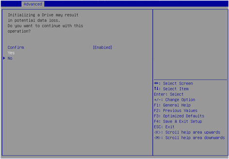
5. On the screen as shown in Figure 60, select Confirm and press Enter. On the dialog box that opens, select Enabled and press Enter. Then, select Yes and press Enter.
Figure 60 Confirming the initialization
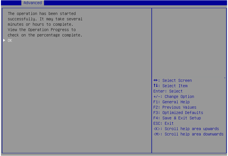
When the operation is complete, the screen as shown in Figure 61 opens.
Figure 61 Completing the operation
Erasing drives
|
|
CAUTION: To avoid drive failure, do not perform other operations when erasing a physical drive. |
This task allows you to erase data from physical and logical drives.
Erasing a physical drive
1. On the storage controller configuration screen as shown in Figure 62, select Drive Management and press Enter.
Figure 62 Storage controller configuration screen
2. On the screen as shown in Figure 63, select the target drive and press Enter.
Figure 63 Drive Management screen
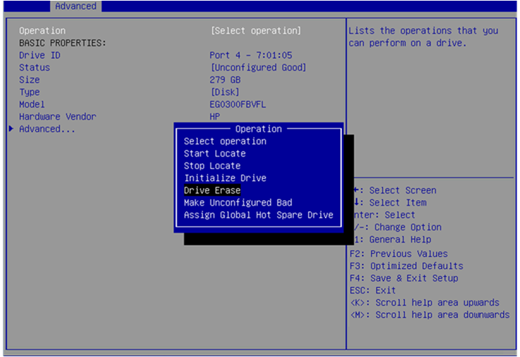
3. On the screen as shown in Figure 64, select Operation and press Enter.
4. On the dialog box that opens, select Drive Erase and press Enter.
For some controllers, you must select Cryptographic Erase for a SAS drive and select Drive Erase for a SATA drive.
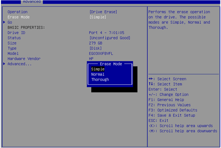
5. On the screen as shown in Figure 65, press Enter and set the Erase Mode (the default Simple mode is recommended).
Figure 65 Setting the Erase Mode
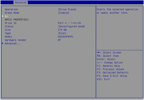
6. On the screen as shown in Figure 66, select Go and press Enter.
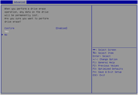
7. On the screen as shown in Figure 67, select Confirm and press Enter. On the dialog box that opens, select Enabled and press Enter. Then, select Yes and press Enter.
Figure 67 Confirming the operation
When the operation is complete, the screen as shown in Figure 68 opens.
Figure 68 Completing the operation
Erasing a logical drive
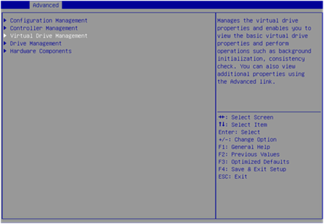
1. On the storage controller configuration screen as shown in Figure 69, select Virtual Drive Management and press Enter.
Figure 69 Storage controller configuration screen
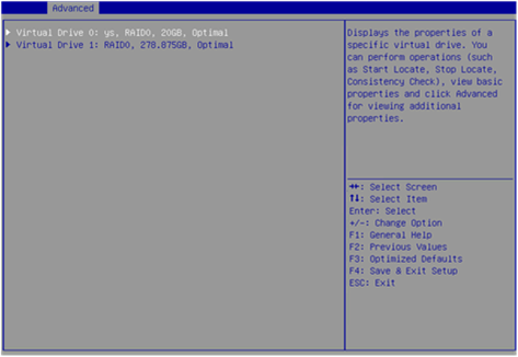
2. On the screen as shown in Figure 70, select the target drive and press Enter.
Figure 70 Virtual Drive Management screen
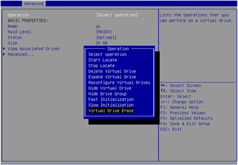
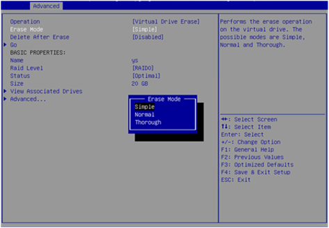
3. On the screen as shown in Figure 71, select Operation and press Enter. On the dialog box that appears, select Virtual Drive Erase and press Enter.
4. On the screen as shown in Figure 72, press Enter and set the Erase Mode (the default Simple mode is recommended).
Figure 72 Setting the Erase Mode
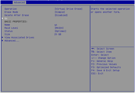
5. On the screen as shown in Figure 73, select Go and press Enter.
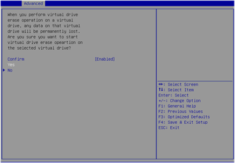
6. On the screen as shown in Figure 74, select Confirm and press Enter. On the dialog box that opens, select Enabled and press Enter. Then, select Yes and press Enter.
Figure 74 Confirming the operation
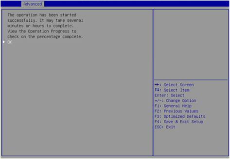
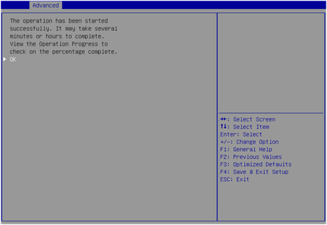
7. When the operation is complete, the screen as shown in Figure 75 opens.
Figure 75 Completing the operation
Expanding a RAID array
This task allows you to expand the RAID array capacity by setting the percentage of available logical drive capacity for availability purposes.
To expand a RAID array:
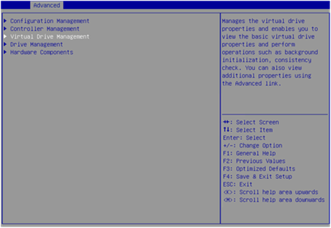
1. On the storage controller configuration screen as shown in Figure 76, select Virtual Drive Management and press Enter.
Figure 76 Storage controller configuration screen
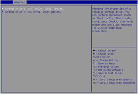
2. On the screen as shown in Figure 77, select the target drive and press Enter.
Figure 77 Virtual Drive Management screen
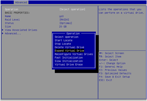
3. On the screen as shown in Figure 78, select Operation and press Enter. On the dialog box that appears, select Expand Virtual Drive and press Enter.
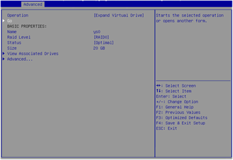
4. On the screen as shown in Figure 79, select Go and press Enter.
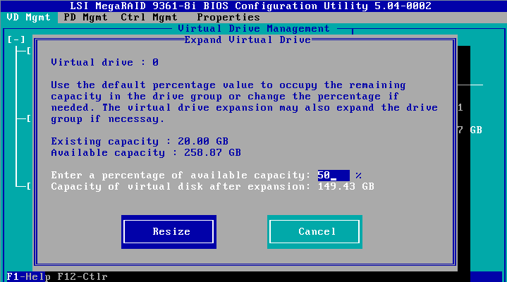
5. On the screen as shown in Figure 80, modify the value for Enter a Percentage of Available Capacity, select OK, and then press Enter.
Figure 80 Setting the percentage of available capacity
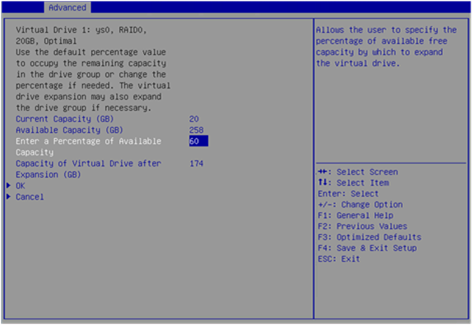
When the operation is complete, the screen as shown in Figure 81 opens.
Figure 81 Completing expanding a RAID array
Migrating the RAID level
This task allows you to change the RAID level without affecting data integrity.
To migrate the RAID level:
1. On the storage controller configuration screen as shown in Figure 82, select Virtual Drive Management and press Enter.
Figure 82 Storage controller configuration screen
2. On the screen as shown in Figure 83, select the target drive and press Enter.
Figure 83 Virtual Drive Management screen
3. On the screen as shown in Figure 84, select Operation and press Enter. On the dialog box that appears, select Reconfigure Virtual Drive and press Enter.
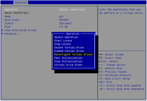
4. On the screen as shown in Figure 85, select Go and press Enter.
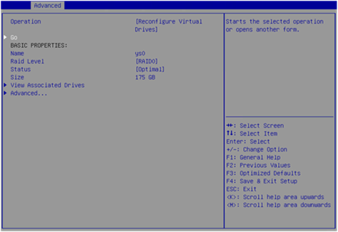
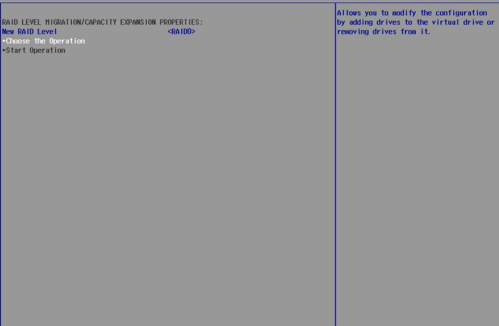
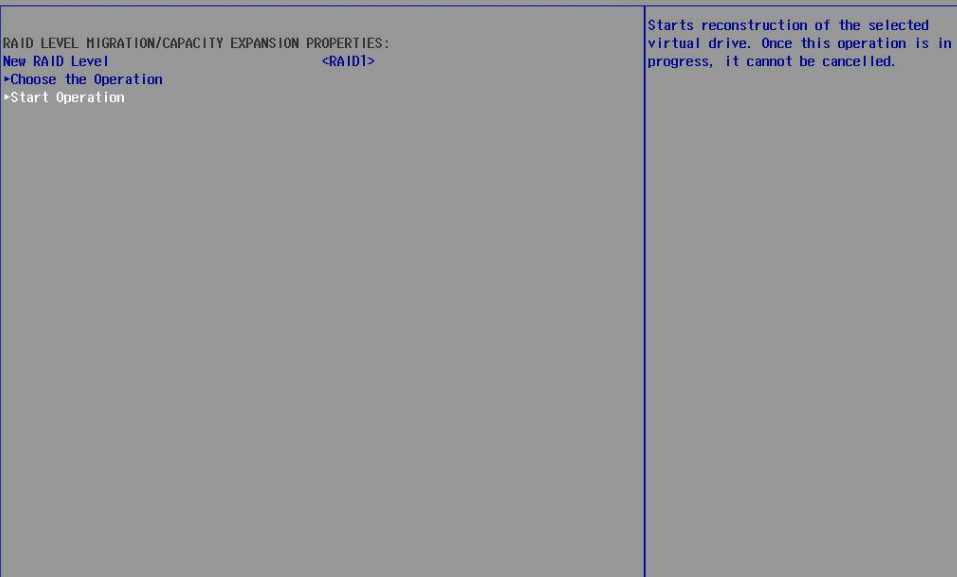
5. On the screen as shown in Figure 86, set the RAID level, select Choose the Operation, and then press Enter.
Figure 86 Choose the operation
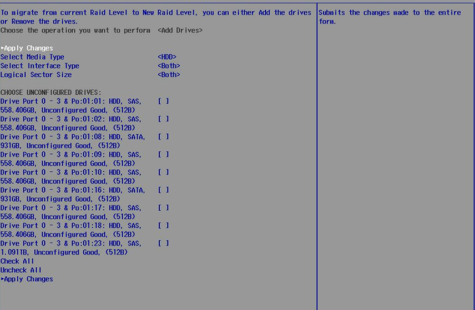
6. On the screen as shown in Figure 87, select the target drives. ([Enabled] following a drive means that the drive has been selected.) Then, select Apply Changes and press Enter.
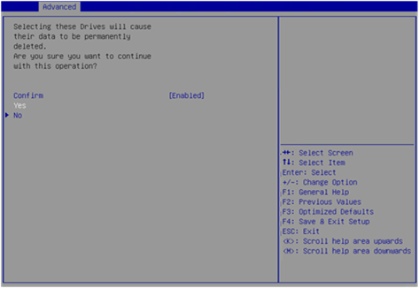
7. On the screen as shown in Figure 88, select Confirm and press Enter. On the dialog box that opens, select Enabled and press Enter. Then, select Yes and press Enter.
Figure 88 Confirming the operation
8. On the screen as shown in Figure 89, select Start Operation, and then press Enter.
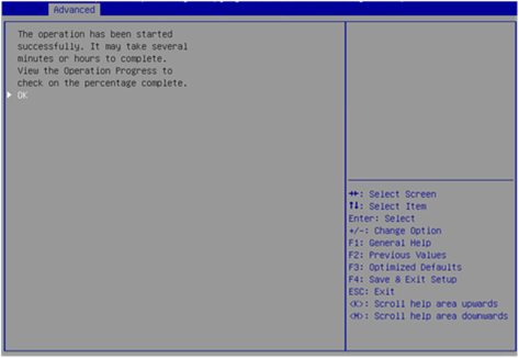
9. On the screen as shown in Figure 90, select OK, and then press Enter.
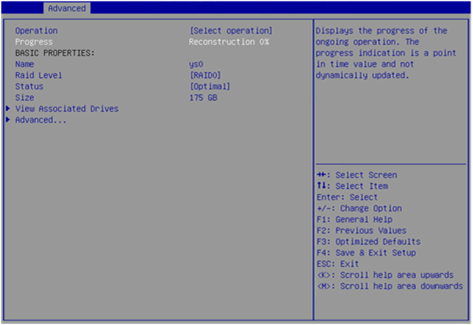
10. On the screen as shown in Figure 91, you can view the migration progress.
Figure 91 Viewing the migration progress
Clearing RAID array information on the drive
This task allows you to clear remaining RAID array information on the drive for reconfiguring RAID array on the drive. The task typically applies to drives in Unconfigured Bad state.
To clear RAID array information on the drive:
1. Switch the drive state from Unconfigured Bad to Unconfigured Good. For more information, see "Switching the drive state."
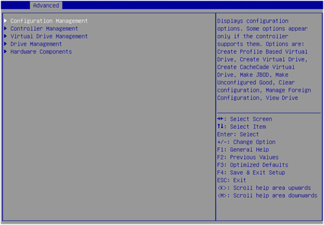
2. On the storage controller configuration screen as shown in Figure 92, select Configuration Management and press Enter.
Figure 92 Storage controller configuration screen
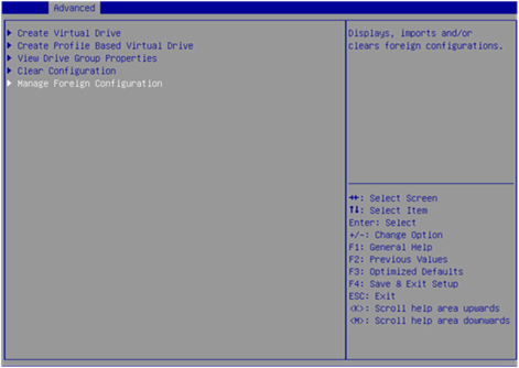
3. On the screen as shown in Figure 93, select Manage Foreign Configuration and press Enter.
Figure 93 Selecting Manage Foreign Configuration
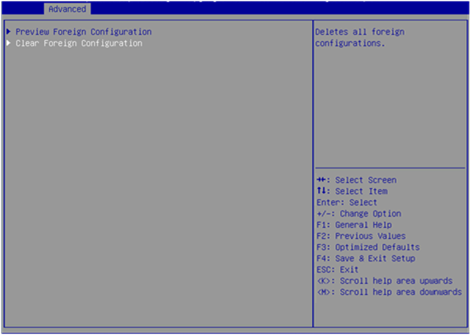
4. On the screen as shown in Figure 94, select Clear Foreign Configuration and press Enter.
Figure 94 Selecting Clear Foreign Configuration
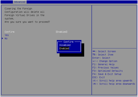
5. On the screen as shown in Figure 95, select Confirm and press Enter. On the dialog box that opens, select Enabled and press Enter. Then, select Yes and press Enter.
Figure 95 Confirming the operation
When the operation is complete, the screen as shown in Figure 96 opens.
Figure 96 Completing the operation
Hiding a virtual drive
This task allows you to hide a virtual drive to avoid unintentional deletion.
To hide a virtual drive:
1. On the storage controller configuration screen as shown in Figure 97, select Virtual Drive Management and press Enter.
Figure 97 Storage controller configuration screen
2. On the screen as shown in Figure 98, select the target drive and press Enter.
Figure 98 Virtual Drive Management screen
3. On the screen as shown in Figure 99, select Operation and press Enter. On the dialog box that appears, select Hide Virtual Drive and press Enter.
Hiding a RAID array
This task allows you to hide a RAID array to avoid unintentional deletion. If you hide a RAID array, all the virtual drives of the RAID array are hidden.
To hide a RAID array:
1. On the storage controller configuration screen as shown in Figure 100, select Virtual Drive Management and press Enter.
Figure 100 Storage controller configuration screen
2. On the screen as shown in Figure 101, select the target drive and press Enter.
Figure 101 Virtual Drive Management screen
3. On the screen as shown in Figure 102, select Operation and press Enter. On the dialog box that appears, select Hide Drive Group and press Enter.
Upgrading the storage controller firmware online
To use a USB drive for the firmware upgrade, save the firmware file in the root directory or a level-1 folder of the USB drive.
To upgrade the storage controller firmware online:
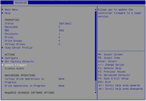
1. On the Advanced screen as shown in Figure 103, select Update Firmware and press Enter.
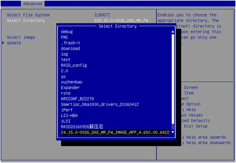
2. On the screen as shown in Figure 104, select the directory of the target firmware and press Enter.
Figure 104 Selecting directory
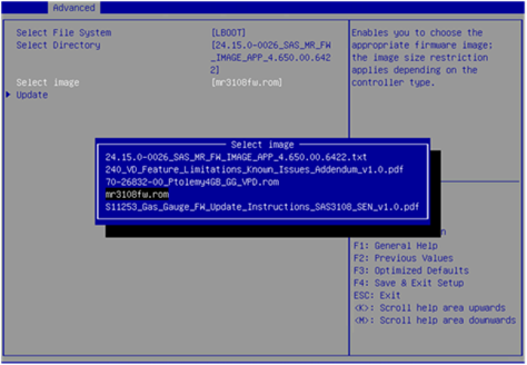
3. On the screen as shown in Figure 105, select the image file of the target firmware and press Enter.
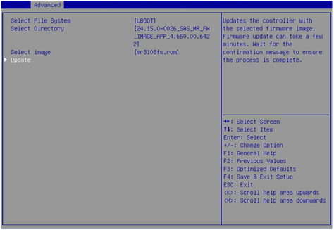
4. On the screen as shown in Figure 106, select Update and press Enter.
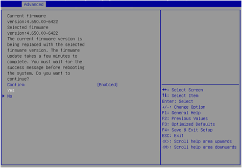
5. On the screen as shown in Figure 107, select Confirm and press Enter. On the dialog box that opens, select Enabled and press Enter. Then, select Yes and press Enter.
|
|
CAUTION: After confirming the upgrade, the screen is stuck for a short time during which the firmware is being upgraded. Do not perform any other operations during this time. |
Figure 107 Confirming the operation
6. On the screen as shown in Figure 108, select OK and press Enter.
Figure 108 Completing the operation
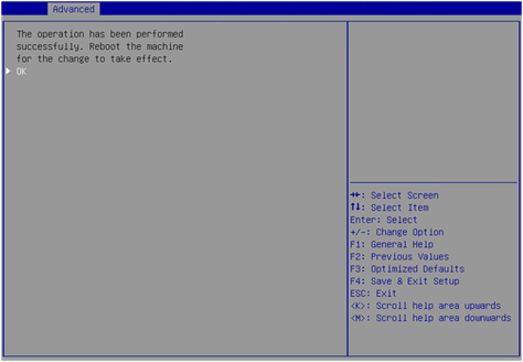
7. Restart the BIOS for the operation to take effect.
Switching the storage controller mode
1. On the Advanced menu, select Main Menu and press Enter.
Figure 109 Selecting Main Menu
2. Select Controller Management and press Enter.
Figure 110 Selecting Controller Management
3. Select Advanced Controller Management and press Enter.
Figure 111 Selecting Advanced Controller Management
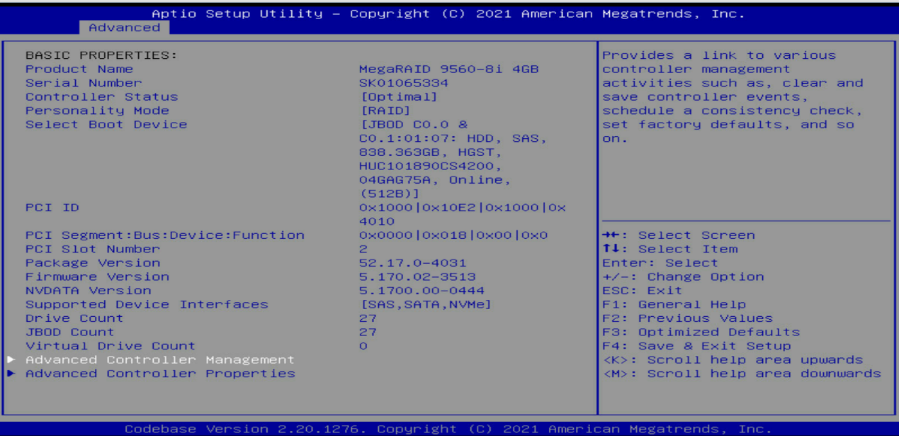
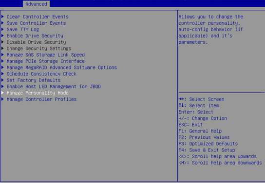
4. Select Manage Personality Mode and press Enter.
Figure 112 Selecting Manage Personality Mode
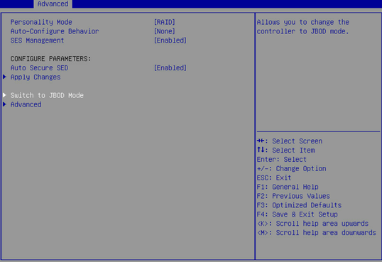
As shown in Figure 113, the storage controller is now is RAID mode. To switch the controller to JBOD mode, select Switch to JBOD Mode and press Enter.
Figure 113 Switching the controller to JBOD mode
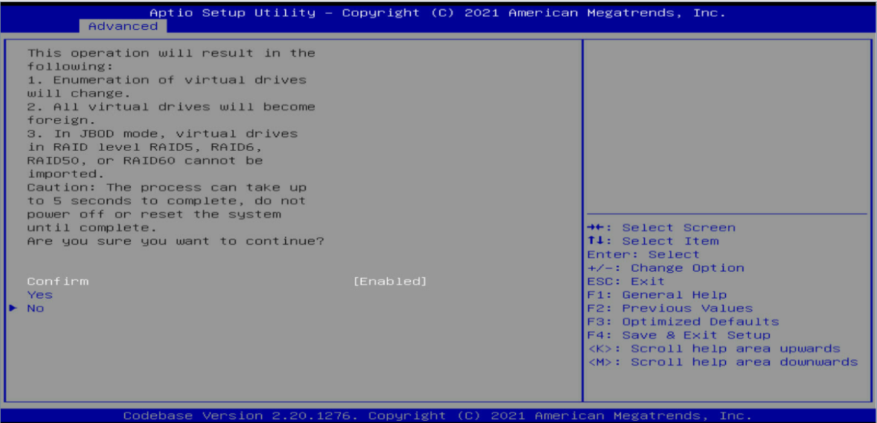
5. Select Confirm to enable the specified mode, select Yes and then press Enter.
|
|
CAUTION: When switching the storage controller to JBOD mode, you can also change logical drives managed by the controller to JBOD mode at the same time. Be careful that data might be cleared for logical drives that do not support JBOD mode once you switch the mode. For example, logical drives in RAID 5, RAID 6, RAID 50, or RAID 60 managed by RAID-LSI-9560-LP-8i-4GB storage controller do not support JBOD mode and will be cleared if you switch their mode. For more information, see the screen prompt. |
Figure 114 Confirming the mode switching
6. Select OK and press Enter to reboot the operating system for the change to take effect.
Figure 115 Completing the mode switching
Configuring RAID arrays in legacy mode
This section describes how to configure RAID arrays through a storage controller in legacy mode. For more information about how to enter the BIOS and set the boot mode to legacy, see the BIOS user guide for the server.
Only the LSI-9361 series storage controllers support RAID array configuration in legacy mode. The other storage controllers support displaying managed physical drives and logical drives on the POST screen in legacy mode, but do not support accessing the storage controller configuration screen.
RAID array configuration tasks at a glance
To configure a RAID array in legacy, perform the following tasks:
· Accessing the storage controller configuration screen
· (Optional.) Configuring hot spare drives
· (Optional.) Deleting a RAID array
· (Optional.) Locating drives
· (Optional.) Initializing a virtual drive
· (Optional.) Erasing drives
· (Optional.) Expanding a RAID array
· (Optional.) Clearing RAID array information on the drive
· (Optional.) Configuring boot options
Accessing the storage controller configuration screen
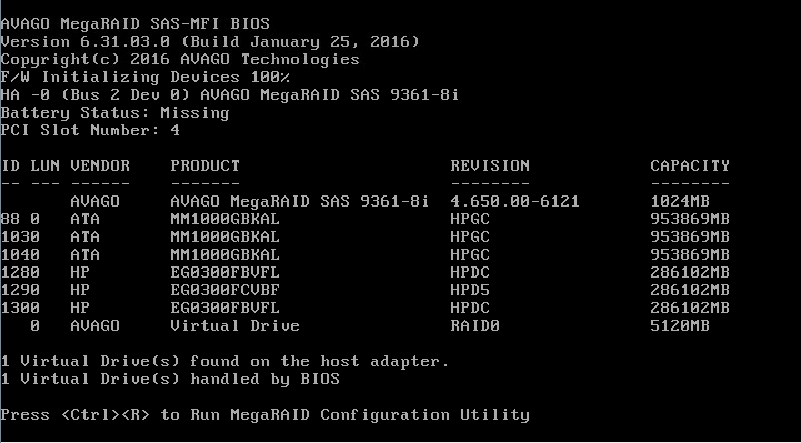
1. During server POST, press Ctrl+R as prompted as shown in Figure 116.
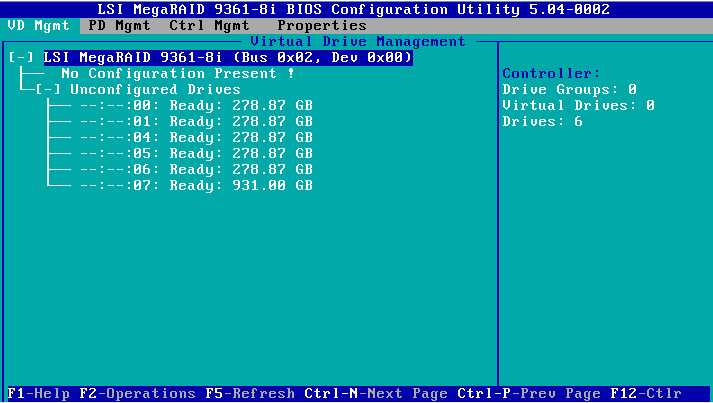
2. On the screen as shown in Figure 117, follow the instructions at the bottom of the screen to navigate through screens and modify settings.
Figure 117 LSI RAID management screen
Switching the drive state
The storage controller supports the following drive states:
· Unconfigured Good—The drive is normal and can be used for RAID array or hot backup configuration.
· Unconfigured Bad—The drive is faulty or has RAID array information remaining on it. If the drive is faulty, replace the drive. If the drive has RAID array information remaining on it, clear the information.
· JBOD—Just a Bunch Of Drives. The drive is a passthrough drive and does not support RAID configuration.
To switch from Unconfigured Bad state to Unconfigured Good state:
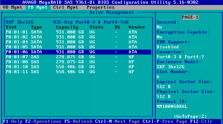
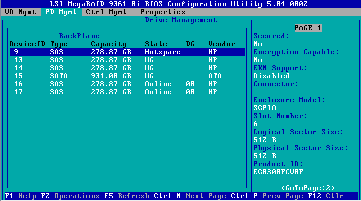
1. On the PD Mgmt screen as shown in Figure 118, select the target drive and press F2.
Figure 118 Selecting the target drive
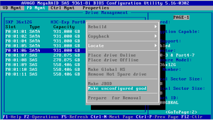
2. On the screen as shown in Figure 119, select Make unconfigured good and press Enter.
Figure 119 Selecting Make unconfigured good
Configuring a RAID array
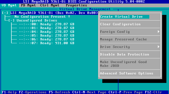
1. On the VD Mgmt screen as shown in Figure 120, press F2 and select Create Virtual Drive.
Figure 120 Selecting Create Virtual Drive
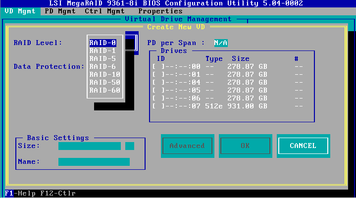
2. On the screen as shown in Figure 121, set the RAID level and press Enter.
Figure 121 Setting the RAID level
3. On the screen as shown in Figure 122, select the target drive and press Enter.
Figure 122 Selecting the target drive

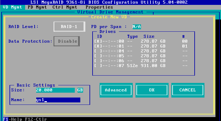
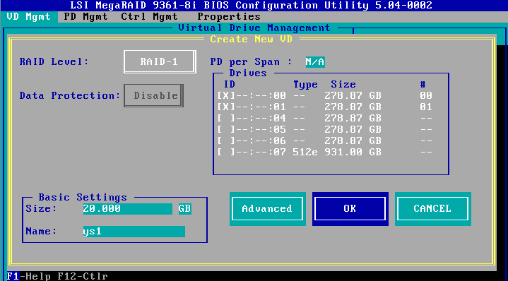
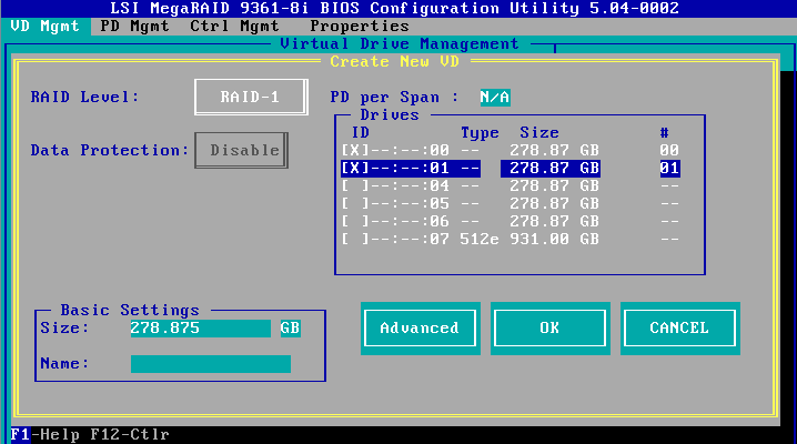
4. On the screen as shown in Figure 123, specify the size and name, select Advanced, and then press Enter.
Figure 123 Specifying the RAID array name and size
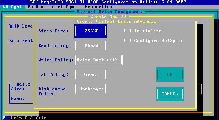
5. On the screen as shown in Figure 124, configure the parameters, select OK, and then press Enter. For more information about the parameter description, see Table 3.
Figure 124 Configuring advanced RAID array parameters
6. On the screen as shown in Figure 125, select OK, and then press Enter.
Figure 125 Confirming the creation
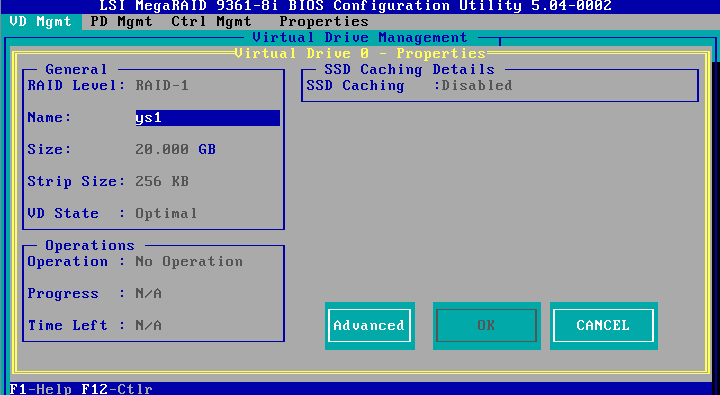
7. On the screen as shown in Figure 126, select the target RAID array and press Enter. You can view the detailed information about the RAID array, including name, level, and drive information.
Figure 126 Viewing RAID array information
Configuring hot spare drives
For data security purposes, configure hot spare drives after configuring a RAID array. You can configure a global hot spare drive or dedicated hot spare drive.
|
|
NOTE: · A hot spare drive can be used only for RAID levels with redundancy. · The capacity of the hot spare drive must be equal to or greater than the capacity of the smallest drive in the RAID array. · Only the drive in Unconfigured Good state can be configured as a hot spare drive. |
Configuring a global hot spare drive
1. On the PD Mgmt screen as shown in Figure 127, select the target drive and press F2.
Figure 127 Selecting the target drive

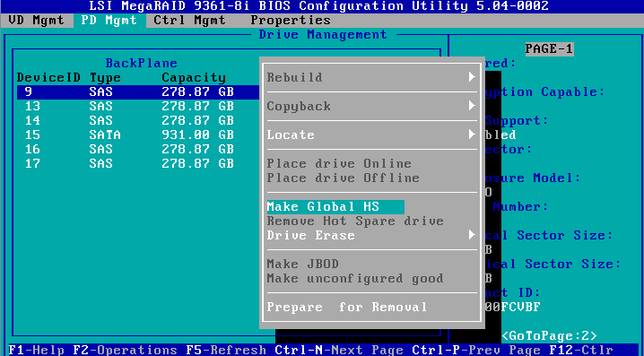
2. On the screen as shown in Figure 128, select Make Global HS and press Enter.
Figure 128 Selecting Make Global HS
3. On the screen as shown in Figure 129, you can view global hot spare drive information by selecting the target drive.
Figure 129 Viewing global hot spare drive information
Configuring a dedicated hot spare drive
1. On the VD Mgmt screen, press F2 and then select Manage Ded.SH.
2. On the screen as shown in Figure 130, select the target drive, select Advanced, and then press Enter.
Figure 130 Selecting the target virtual drive
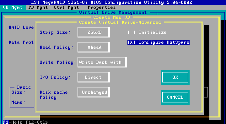
3. On the screen as shown in Figure 131, select Configure HotSpare, select OK, and then press Enter.
Figure 131 Selecting Configure HotSpare
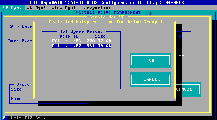
4. On the screen as shown in Figure 132, select the target drive, select OK, and then press Enter.
Figure 132 Selecting the target drive
Deleting a RAID array
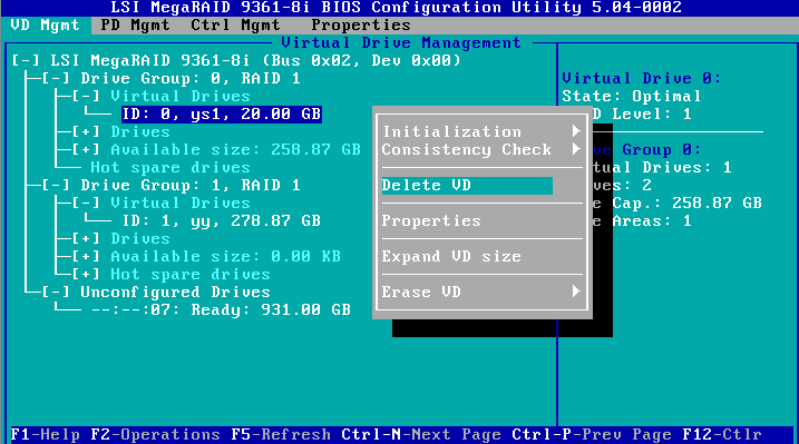
1. On the VD Mgmt screen as shown in Figure 133, select the target drive and press F2.
Figure 133 Selecting the target drive

2. On the screen as shown in Figure 134, select Delete VD and press Enter.
Figure 134 Selecting Delete VD
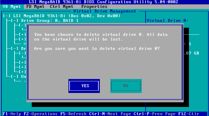
3. On the screen as shown in Figure 135, select YES and press Enter.
Figure 135 Confirming the operation
Locating drives
This task allows you to locate a physical drive.
To locate drives:
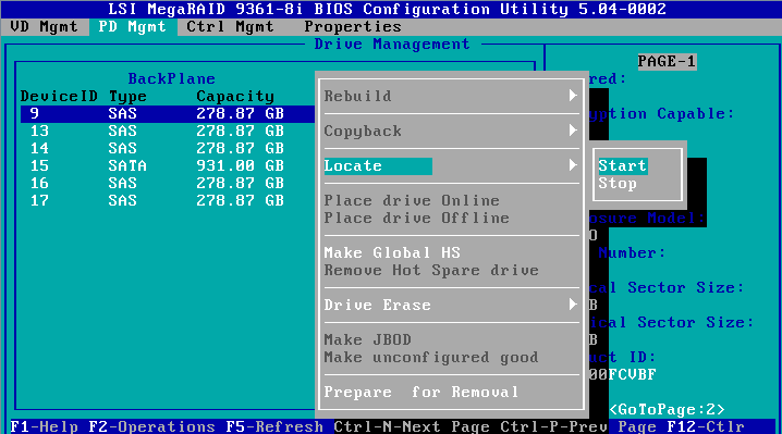
1. On the PD Mgmt screen as shown in Figure 136, select the target drive and press F2.
Figure 136 Selecting the target drive

2. On the screen as shown in Figure 137, select Locate > Start. The Fault/UID LED on the drive turns steady blue. To stop locating drives, select Locate > Stop.
Figure 137 Selecting Locate > Start
Initializing a virtual drive
This task allows you to initialize a virtual drive to be used by operating systems.
To initialize a virtual drive:
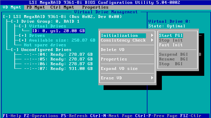
1. On the VD Mgmt screen as shown in Figure 138, select the target drive and press F2.
Figure 138 Selecting the target drive

2. On the screen as shown in Figure 139, select Initialization > Start FGI.
Figure 139 Selecting Initialization > Start FGI
|
|
NOTE: · Background Initialization (BGI) first initializes part of the RAID array space for data write operations, and initializes the rest of the RAID array space in the background. · Full Ground Initialization (FGI) initializes the entire RAID array space. Data write operations can be performed only when the initialization is complete. |
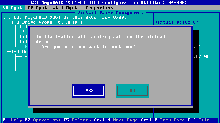
3. On the screen as shown in Figure 140, select YES and press Enter.
Figure 140 Confirming the operation
Erasing drives
|
|
CAUTION: To avoid drive failure, do not perform other operations when erasing a physical drive. |
This task allows you to erase physical and logical drives.
Erasing a physical drive
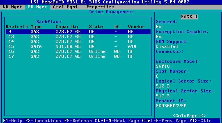
1. On the PD Mgmt screen as shown in Figure 141, select the target drive and press F2.
Figure 141 Selecting the target drive
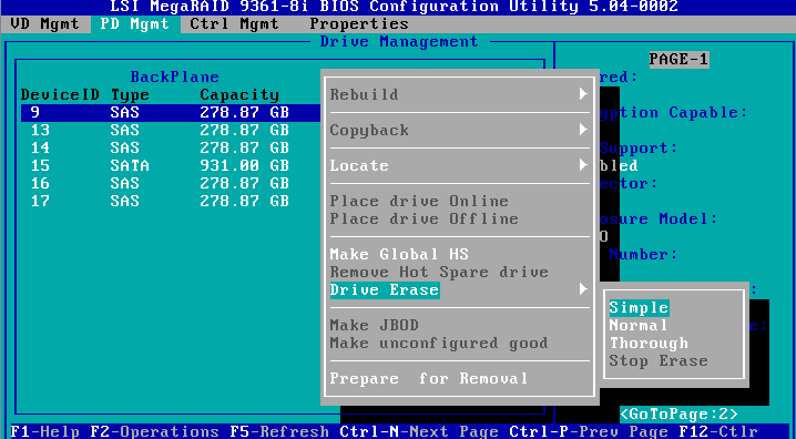
2. On the screen as shown in Figure 142, select the erase mode (the default Simple mode is recommended) and press Enter.
Figure 142 Selecting the erase mode
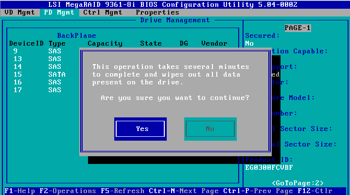
3. On the screen as shown in Figure 143, select Yes and press Enter.
Figure 143 Confirming the operation
Erasing a logical drive
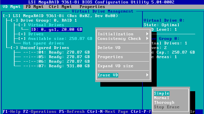
1. On the VD Mgmt screen as shown in Figure 144, select the target drive and press F2.
Figure 144 Selecting the target drive

2. On the screen as shown in Figure 145, select the erase mode (the default Simple mode is recommended) and press Enter.
Figure 145 Selecting the erase mode
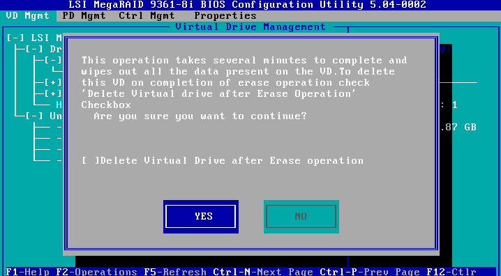
3. On the screen as shown in Figure 146, select YES and press Enter.
Figure 146 Confirming the operation
Expanding a RAID array
This task allows you to expand the RAID array capacity by setting the percentage of available capacity for logical drives.
To expand a RAID array:
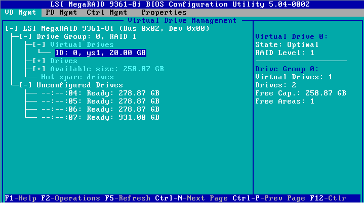
1. On the VD Mgmt screen as shown in Figure 147, select the target drive and press F2.
Figure 147 Selecting the target drive
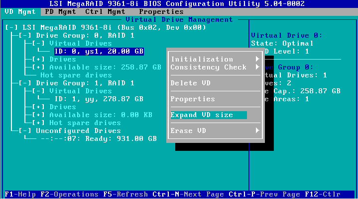
2. On the screen as shown in Figure 148, select Expand VD size and press Enter.
Figure 148 Selecting Expand VD size
3. On the screen as shown in Figure 149, modify the value for Enter a percentage of available capacity as needed, select Resize, and then press Enter.
Figure 149 Setting the percentage of available capacity
Clearing RAID array information on the drive
This task allows you to clear remaining RAID array information on the drive for reconfiguring RAID array on the drive.
To clear RAID array information on the drive:
1. Switch the drive state from Unconfigured Bad to Unconfigured Good. For more information, see "Switching the drive state."
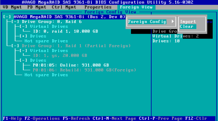
2. On the Foreign View screen as shown in Figure 150, select the target storage controller and press F2. Select Foreign Config > Clear and press Enter.
Figure 150 Selecting Foreign Config > Clear
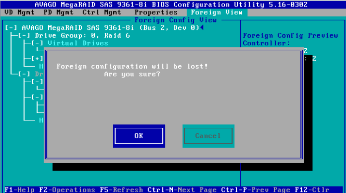
3. On the dialog box that appears as shown in Figure 151, select OK and press Enter.
Figure 151 Confirming the operation
Configuring boot options
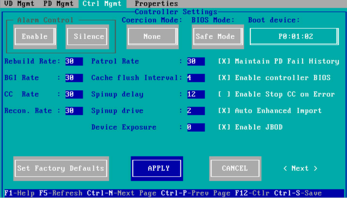
1. On the Ctrl Mgmt screen as shown in Figure 152, select the target physical drive or logical drive as the boot device and then press Enter.
Figure 152 Selecting the boot device
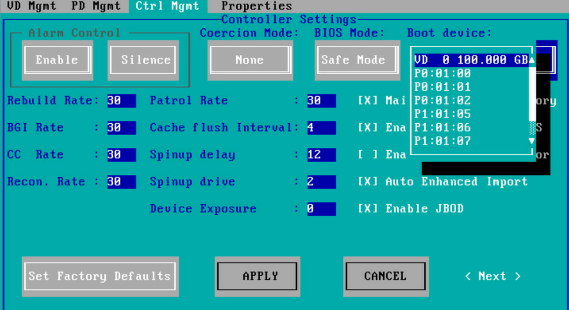
2. Select APPLY and then press Enter as shown in Figure 153.
Figure 153 Confirming the operation