- Table of Contents
-
- H3C Servers Storage Controller User Guide-6W107
- 00-Preface
- 01-Storage controller overview
- 02-Storage controller features
- 03-Configuring an embedded RSTe RAID controller
- 04-Configuring an NVMe VROC module
- 05-Configuring a P430 storage controller
- 06-Configuring a 1000 storage controller
- 07-Configuring a 9361, 9440, 9460, L460, P5408, or H5408 storage controller
- 08-Configuring an H460, P460, P240 or P4408 storage controller
- 09-Configuring a 9300 storage controller
- 10-Configuring a 9311 storage controller
- 11-Configuring an LSI 9400 or 9500 series storage controller
- 12-Configuring a RAID-MARVELL-SANTACRUZ-LP-2i storage controller
- 13-Appendix A Troubleshooting storage controllers
- 14-Appendix B RAID arrays and fault tolerance
- Related Documents
-
10-Configuring a 9311 storage controller
Configuring an HBA-LSI-9311-8i storage controller
About the HBA-LSI-9311-8i storage controller
The HBA-LSI-9311-8i storage controller supports 12-Gbps data channels. For storage controller details, contact Technical Support.
Features
RAID levels
Table 1 shows the minimum number of drives required by each RAID level and the maximum number of failed drives supported by each RAID level. For more information about RAID levels, see "Appendix B RAID arrays and fault tolerance."
Table 1 RAID levels and the numbers of drives for each RAID level
|
RAID level |
Min. drives required |
Max. failed drives |
|
RAID 0 |
2 |
0 |
|
RAID 1 |
2 |
1 |
|
RAID 1E |
3 |
Integer part of n/2, where n is the number of drives in the RAID 1E array. |
|
RAID 10 |
4 |
n, where n is the number of RAID 1 arrays in the RAID 10 array. |
Hot spare drives
You can configure hot spare drives to improve data security. A hot spare drive is a standby drive that does not store any data. When a drive in a redundant RAID fails, a spare drive automatically replaces the failed drive and rebuilds the data of the failed drive.
For information about types of hot spare drives, see hot spare drives in "Storage controller features."
Restrictions and guidelines for RAID configuration
As a best practice, install drives that do not contain RAID information.
To avoid degraded RAID performance or RAID creation failures, make sure all drives in the RAID are the same type (HDDs or SSDs) and have the same connector type (SAS or SATA).
For efficient use of storage, use drives that have the same capacity to build a RAID. If the drives have different capacities, the lowest capacity is used across all drives in the RAID.
If one drive is used by several logical drives, RAID performance might be affected and maintenance complexities will increase.
Configuring RAID arrays in UEFI mode
This section describes how to configure RAID arrays through a storage controller in UEFI mode. For more information about how to enter the BIOS and set the boot mode to UEFI, see the BIOS user guide for the server.
RAID arrays configuration tasks at a glance
To configure RAID arrays in UEFI mode, perform the following tasks:
· Accessing the controller configuration screen
· (Optional.) Configuring hot spare drives
· (Optional.) Deleting a RAID array
· (Optional.) Clearing RAID array information on the drive
· (Optional.) View basic controller properties
· (Optional.) Changing controller properties
· (Optional.) Viewing drive properties
· (Optional.) Locating drives
Accessing the controller configuration screen
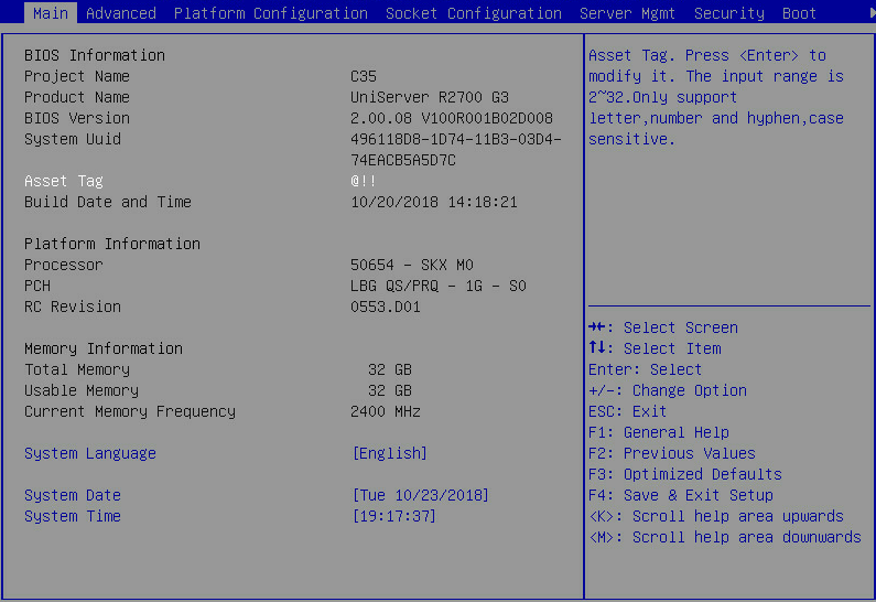
1. Access the BIOS. Press Delete, Esc, or F2 as prompted during server POST to open the BIOS setup screen as shown in Figure 1. For some servers, the Front Page screen opens, and you must select Device Management before proceeding to the next step.
For how to navigate screens and modify settings, see the operation instructions at the lower right corner.
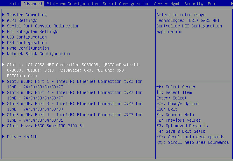
2. Access the LSI SAS3 MPT Controller SAS3008 submenu. Select Advanced > LSI SAS3 MPT Controller SAS3008, and press Enter.
Figure 2 Advanced screen
3. On the screen as shown in Figure 3, select LSI SAS3 MPT Controller Version 18.00.00.00, and press Enter.
Figure 3 Selecting the LSI SAS3 MPT controller
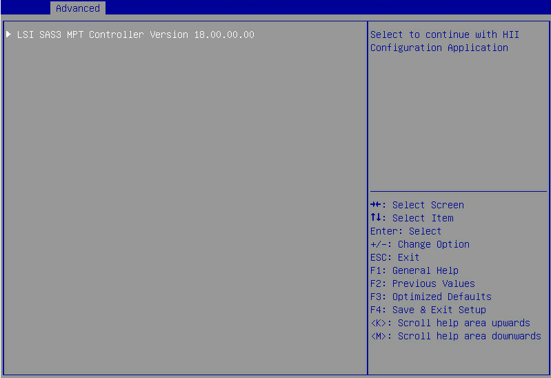
The controller configuration screen as shown in Figure 4 opens.
Figure 4 Controller configuration screen

Configuring a RAID array
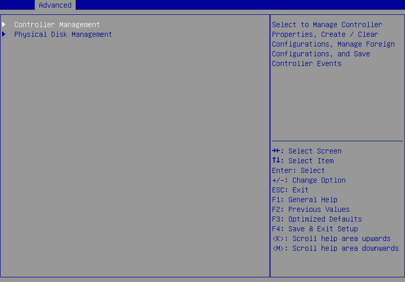
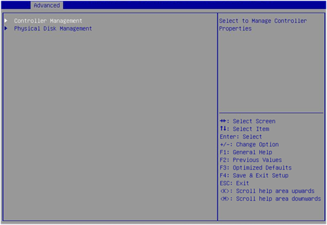
1. On the storage controller configuration screen as shown in Figure 5, select Controller Management and press Enter.
Figure 5 Storage controller configuration screen
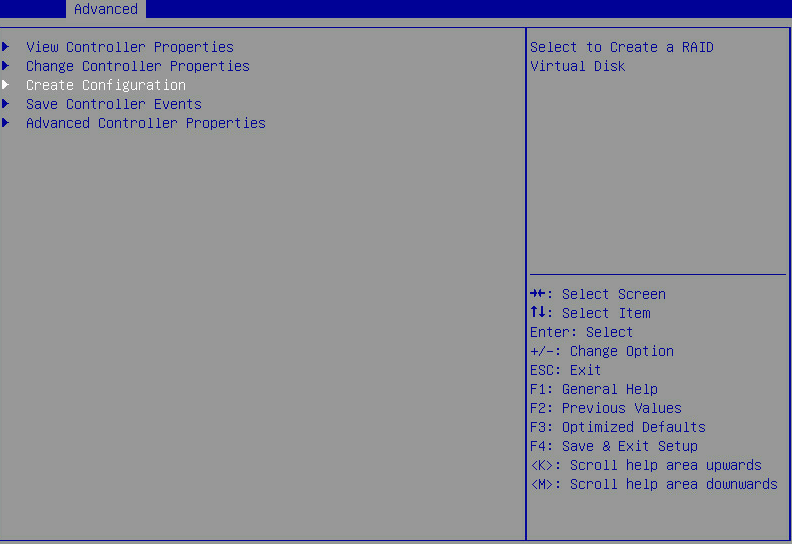
2. On the screen as shown in Figure 6, select Create Configuration and press Enter.
Figure 6 Selecting Create Virtual Drive
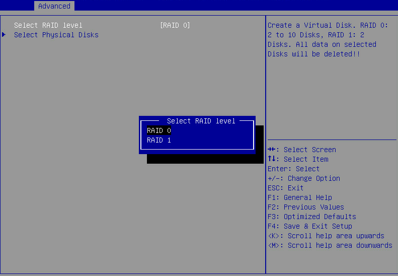
3. On the screen as shown in Figure 7, select Select RAID Level to set the RAID level, and then press Enter.
Figure 7 Setting the RAID level
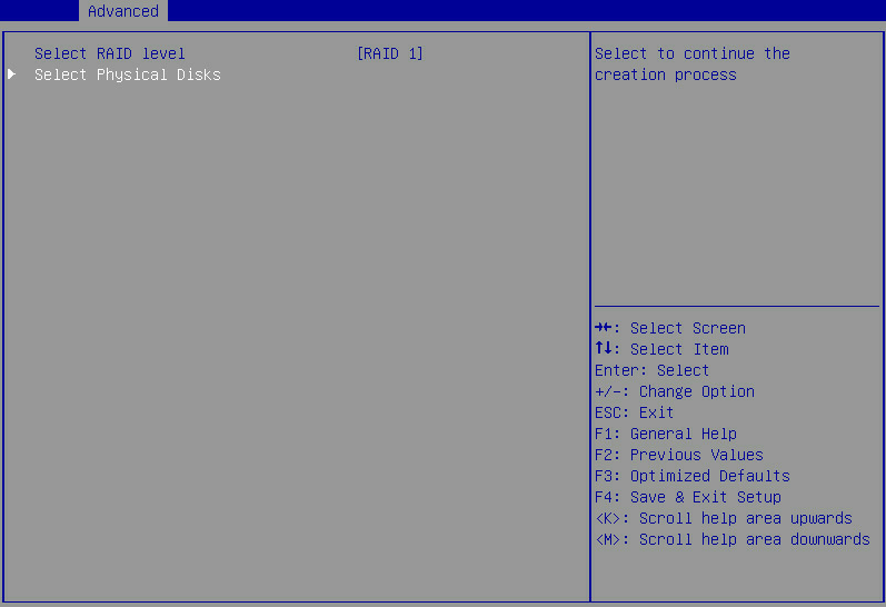
4. On the screen as shown in Figure 8, select Select Physical Disks, and then press Enter.
Figure 8 Selecting Select Physical Disks
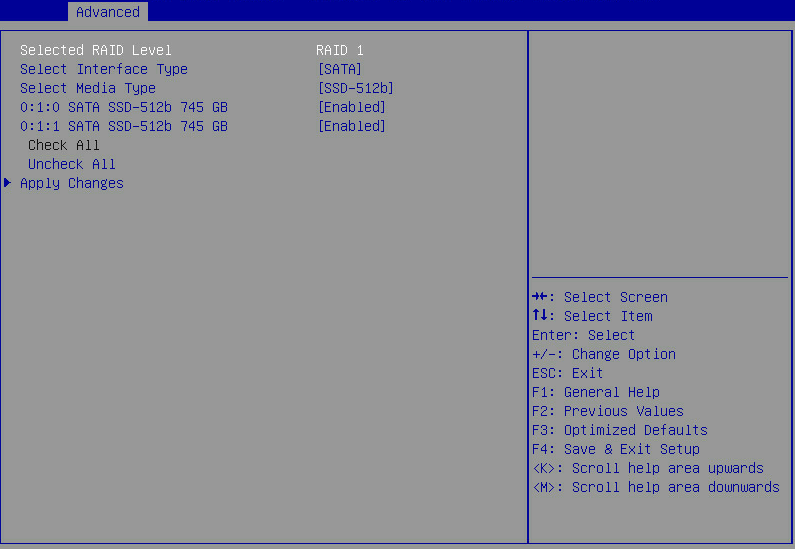
5. On the screen as shown in Figure 9, select the target drives. ([Enabled] following a drive means that the drive has been selected.) Then, select Apply Changes and press Enter.
Figure 9 Selecting the target drives
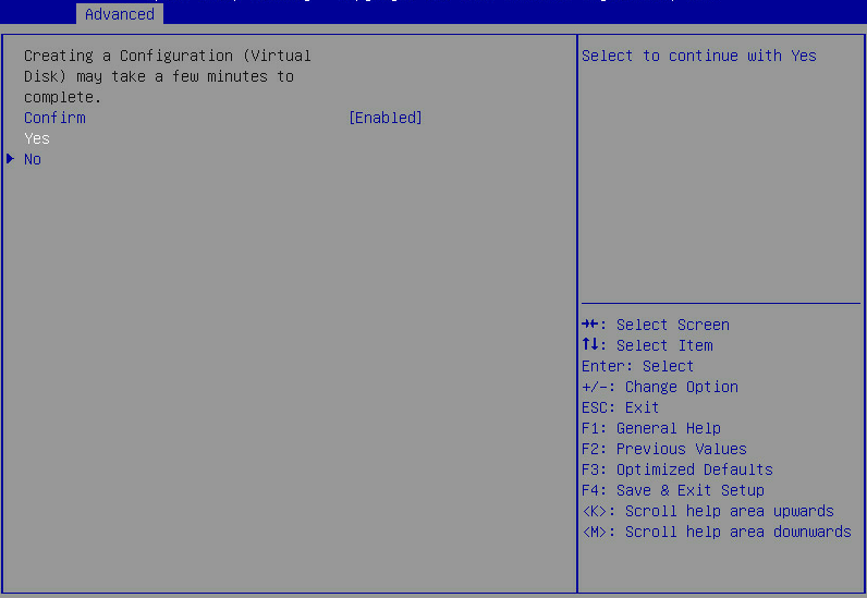
6. On the screen as shown in Figure 10, select Confirm and press Enter. On the dialog box that opens, select Enabled and press Enter. Then, select Yes and press Enter.
Figure 10 Confirming the configuration
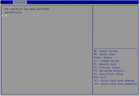
7. On the screen as shown in Figure 11, select OK to return to the storage controller configuration screen.
Figure 11 Completing RAID array configuration
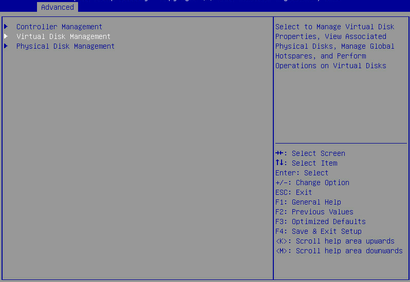
8. Select Virtual Disk Management and press Enter as shown in Figure 12.
Figure 12 Storage controller configuration screen
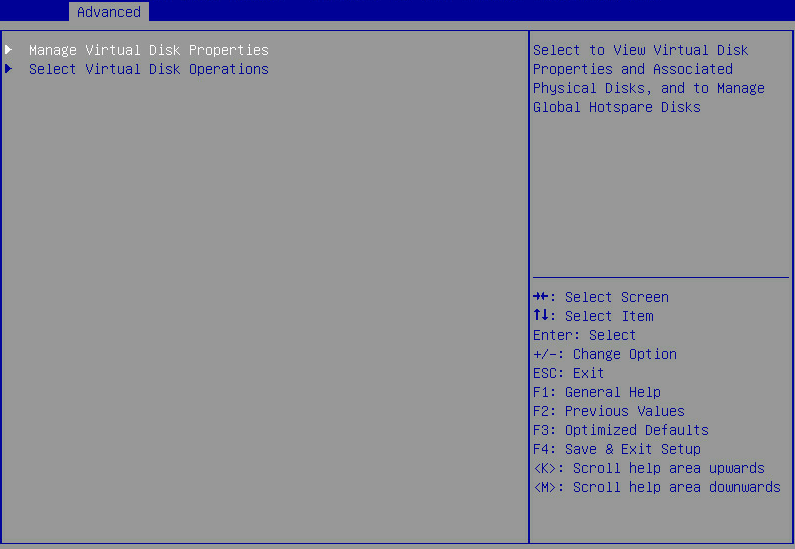
9. On the screen as shown in Figure 13, select Manage Virtual Disk Properties and press Enter.
Figure 13 Virtual Drive Management screen
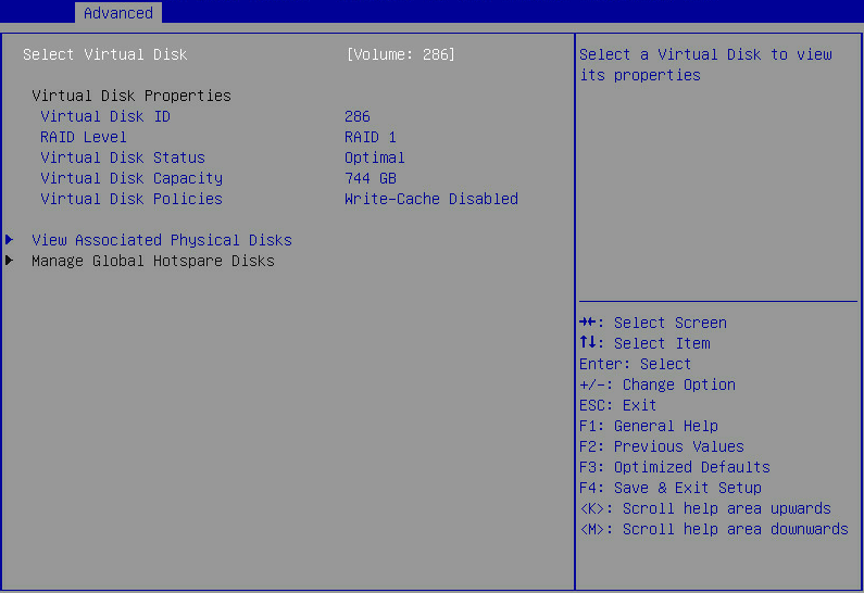
10. On the screen as shown in Figure 14, select View Associated Drives and press Enter. You can view the detailed information about the RAID array, including name, level, and drive information.
Figure 14 Selecting View Associated Drives
Configuring hot spare drives
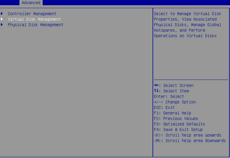
1. On the storage controller configuration screen as shown in Figure 15, select Virtual Disk Management and press Enter.
Figure 15 Storage controller configuration screen

2. On the screen as shown in Figure 16, select Manage Virtual Disk Properties and press Enter.
Figure 16 Array Configuration screen

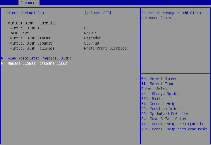
3. On the screen as shown in Figure 17, select Manage Global Hotspare Disks and press Enter.
Figure 17 Selecting Manage Global Hotspare Disks
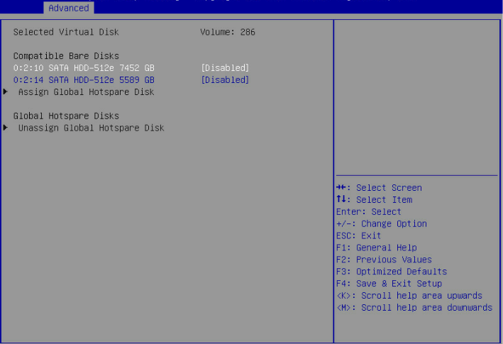
4. On the screen as shown in Figure 18, select the target drives. ([Enabled] following a drive means that the drive has been selected.) Then, select Assign Global Hotspare Disk and press Enter.
Figure 18 Selecting the target drives
Deleting a RAID array
1. On the storage controller configuration screen as shown in Figure 19, select Virtual Disk Management and press Enter.
Figure 19 Storage controller configuration screen
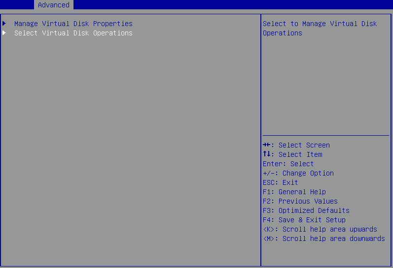
2. On the screen as shown in Figure 20, select Select Virtual Disk Properties and press Enter.
Figure 20 Virtual Drive Management screen
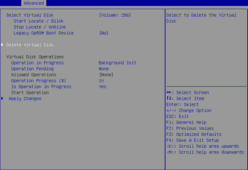
3. On the screen as shown in Figure 21, select Delete Virtual Disk and press Enter.
Figure 21 Selecting Delete Virtual Disk
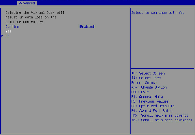
4. On the screen as shown in Figure 22, select Confirm and press Enter. On the dialog box that opens, select Enabled and press Enter. Then, select Yes and press Enter.
Figure 22 Confirming the deletion
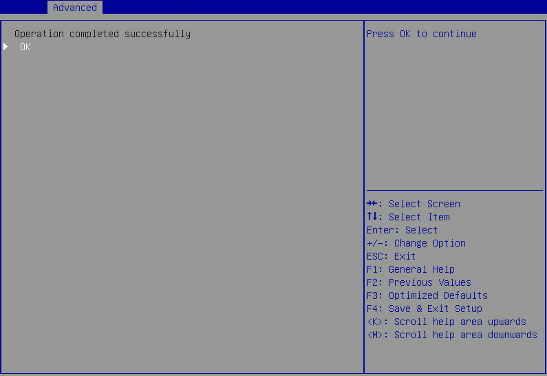
When the operation is complete, the screen as shown in Figure 23 opens.
Figure 23 Completing the operation
Clearing RAID array information on the drive
This task allows you to clear remaining RAID array information on the drive for reconfiguring RAID array on the drive.
To clear RAID array information on the drive:
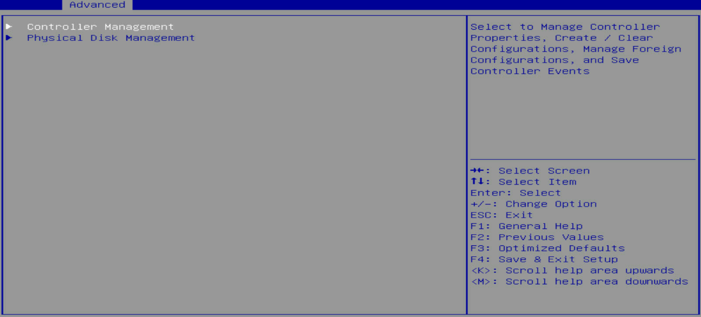
1. On the storage controller configuration screen as shown in Figure 24, select Controller Management and press Enter.
Figure 24 Storage controller configuration screen
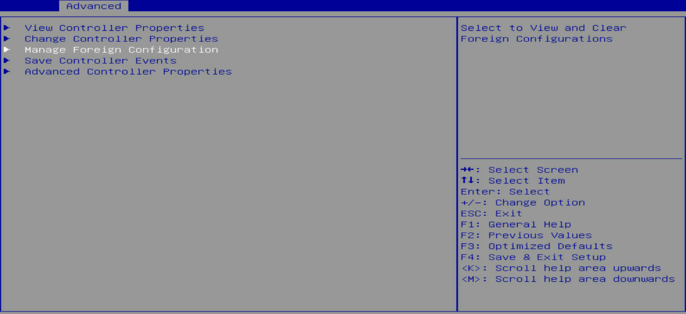
2. On the screen as shown in Figure 25, select Manage Foreign Configuration and press Enter.
Figure 25 Selecting Manage Foreign Configuration
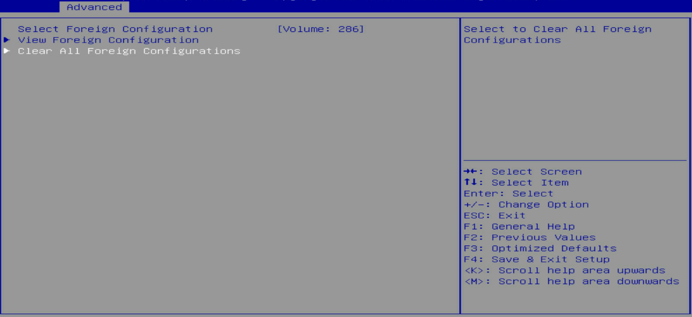
3. On the screen as shown in Figure 26, select Clear All Foreign Configuration and press Enter.
Figure 26 Selecting Clear Foreign Configuration
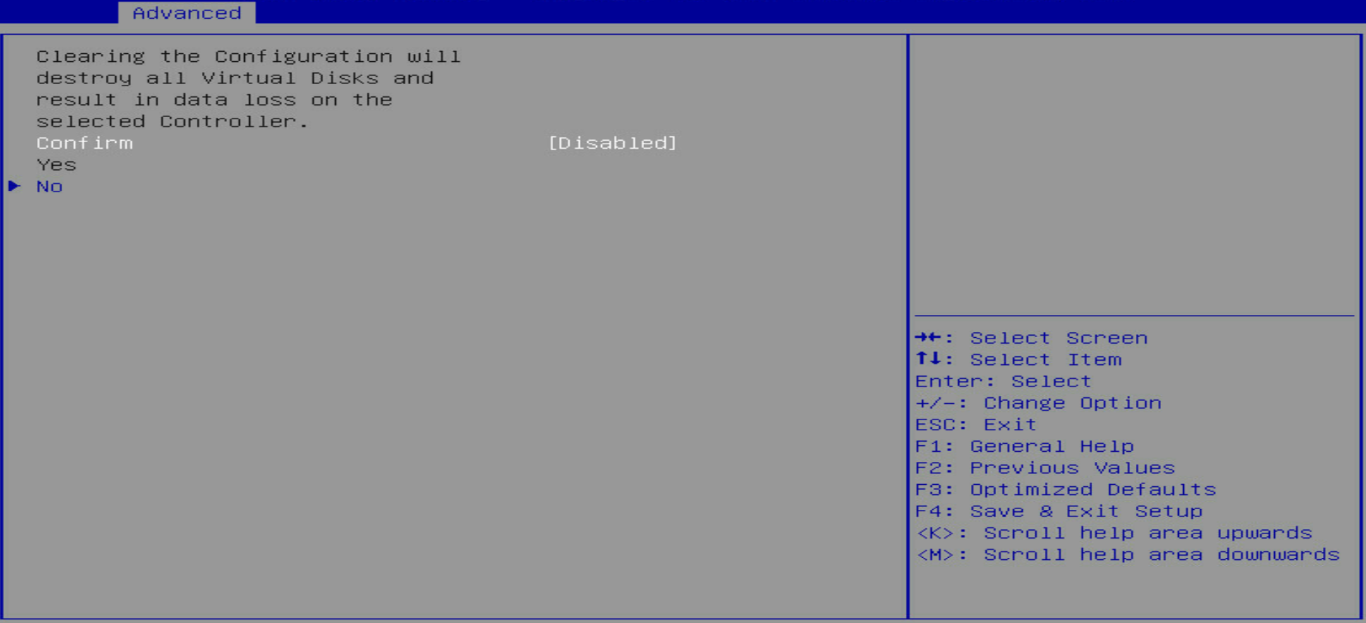
4. On the screen as shown in Figure 27, select Confirm and press Enter. On the dialog box that opens, select Enabled and press Enter. Then, select Yes and press Enter.
Figure 27 Confirming the operation
View basic controller properties
1. On the storage controller configuration screen as shown in Figure 28, select Controller Management and press Enter.
Figure 28 Storage controller configuration screen
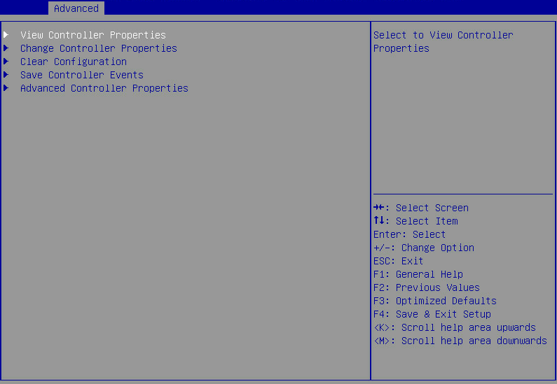
2. On the screen as shown in Figure 29, select View Controller Properties and press Enter.
Figure 29 Selecting View Controller Properties
3. View the controller properties on the screen as shown in Figure 30.
Table 2 describes the properties of the controller.
Figure 30 Viewing controller properties
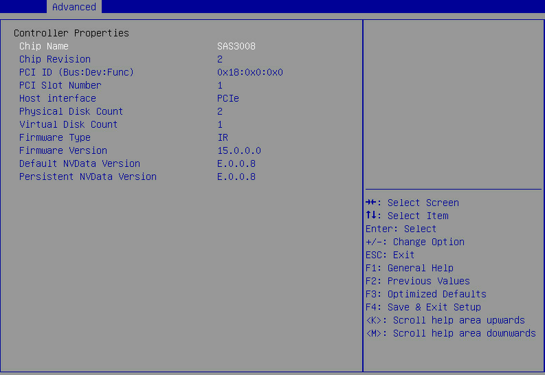
Table 2 Properties of the storage controller
|
Parameter |
Description |
|
Chip Revision |
Version of the chip. |
|
Host interface |
Host interface type. |
|
Persistent NVData Version |
Current NVData version. |
Changing controller properties
1. On the storage controller configuration screen as shown in Figure 31, select Controller Management and press Enter.
Figure 31 Storage controller configuration screen

2. On the screen as shown in Figure 32, select Change Controller Properties and press Enter.
Figure 32 Selecting Change Controller Properties
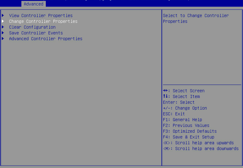
3. On the screen as shown in Figure 33, change the controller settings as needed, select Apply Changes, and press Enter.
Figure 33 Changing advanced controller settings
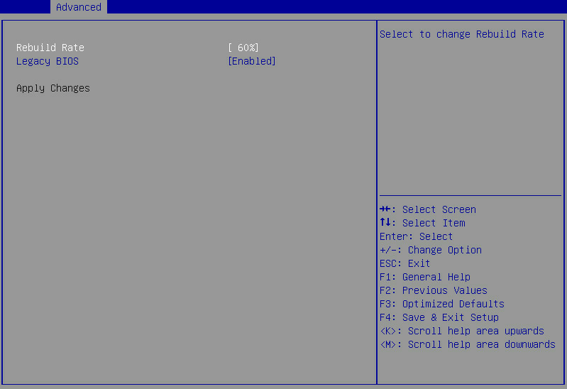
Figure 34 Parameter description
|
Parameter |
Description |
|
Rebuild Rate |
Percentage of I/O resources occupied by RAID rebuild when a new hard drive is installed or a failed hard disk is replaced with a hot spare disk. |
Viewing drive properties
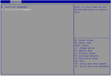
1. On the storage controller configuration screen as shown in Figure 35, select Physical Disk Management and press Enter.
Figure 35 Storage controller configuration screen
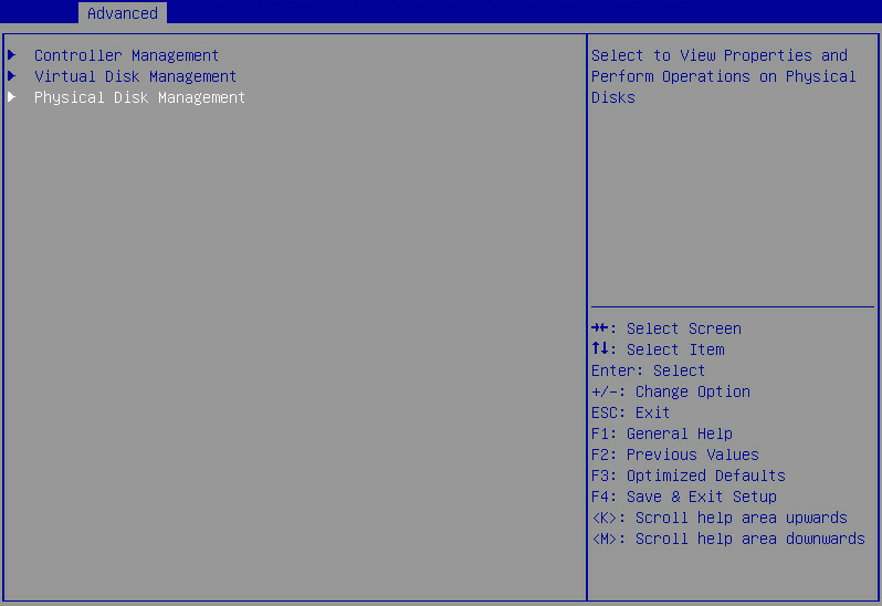
2. On the screen as shown in Figure 36, select View Physical Disk Properties and press Enter.
Figure 36 Selecting View Physical Disk Properties
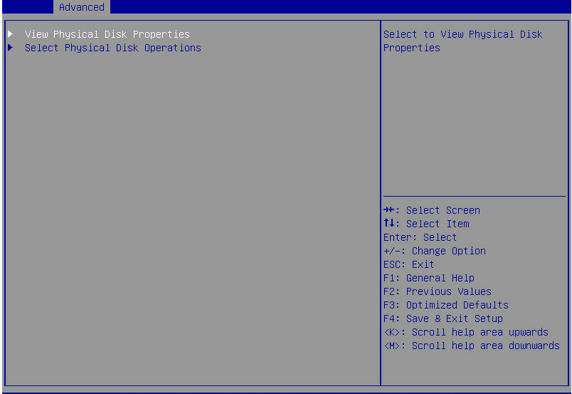
3. On the screen as shown in Figure 37, select Select Physical Disk. On the pop-up window that opens, select the physical drive you want to view and press Enter.
Figure 37 Selecting a physical drive
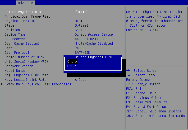
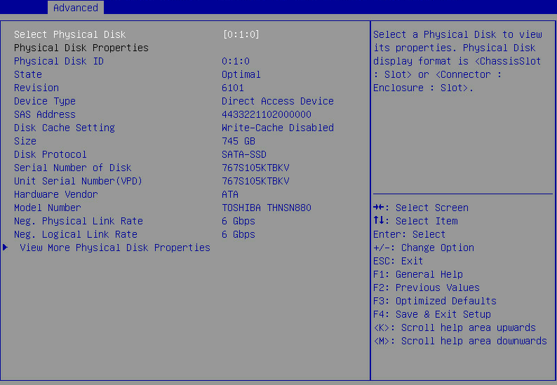
4. View properties of the physical drive on the screen as shown in Figure 38.
You can select View More Physical Disk Properties for more information.
Figure 38 Viewing drive properties
Locating drives
1. On the storage controller configuration screen as shown in Figure 39, select Physical Disk Management and press Enter.
Figure 39 Storage controller configuration screen
2. On the screen as shown in Figure 40, select Select Physical Disk Operations, and press Enter.
Figure 40 Selecting physical disk operations

3. On the screen as shown in Figure 41, select Select Physical Disk. On the pop-up window that opens, select the physical drive you want to locate and press Enter.
Figure 41 Selecting a physical drive
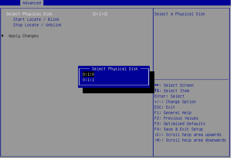
4. Select Start Locate/Blink and press Enter.
5. On the server, identify the physical drive of which the Fault/UID LED is steady blue.
Configuring RAID arrays in legacy mode
This section describes how to configure RAID arrays through a storage controller in legacy mode. For more information about how to enter the BIOS and set the boot mode to legacy, see the BIOS user guide for the server.
RAID array configuration tasks at a glance
To configure RAID arrays in legacy mode, perform the following tasks:
· Accessing the controller configuration screen
· (Optional.) Configuring hot spare drives
· (Optional.) Deleting a RAID array
· (Optional.) Running consistency check
· (Optional.) Viewing drive properties
· (Optional.) Locating drives
· (Optional.) Clearing RAID information or verifying drives
· (Optional.) Setting advanced controller properties
· (Optional.) Configuring boot options
Accessing the controller configuration screen
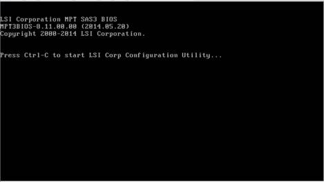
1. During server POST, press Ctrl+C on the screen as shown in Figure 42 to open the controller configuration screen.
Figure 42 Legacy BIOS setup screen
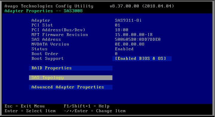
2. On the screen as shown in Figure 43, press Enter.
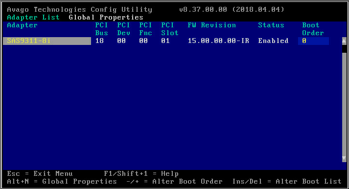
The controller configuration screen as shown in Figure 44 opens.
Figure 44 Controller configuration screen
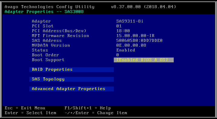
Table 3 Parameter description
|
Parameter |
Description |
|
Adapter |
Storage controller name. |
|
MPT Firmware Revision |
MPT firmware version. |
|
Boot Order |
Boot order for multiple storage controllers. If only one storage controller exists, the field displays 0. |
|
Boot Support |
Support for storage controller management. Options include: · Enabled BIOS & OS—RAID array management is supported for both the BIOS and the OS. · Enabled BIOS Only—RAID array management is supported for the BIOS only. · Enabled OS Only—RAID array management is supported for the OS only. · Disabled—RAID array management is not supported for either the BIOS or the OS. |
Configuring a RAID array
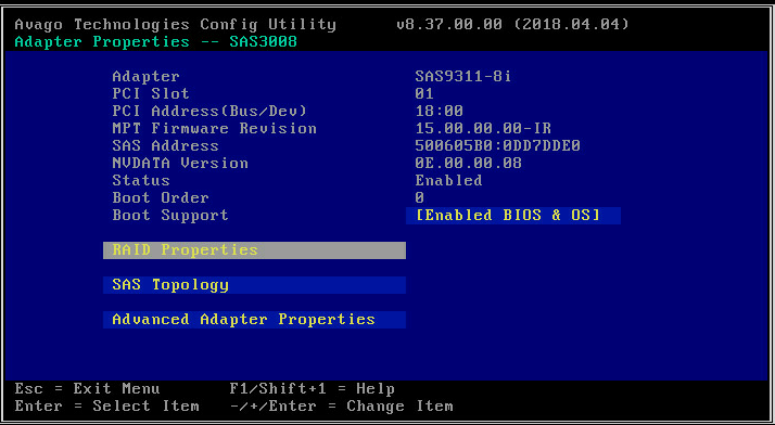
1. On the storage controller configuration screen as shown in Figure 45, select RAID Properties and press Enter.
Figure 45 Storage controller configuration screen
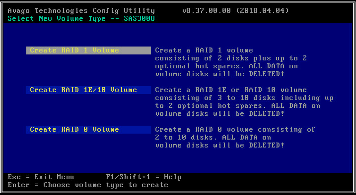
2. On the screen as shown in Figure 46, select a target RAID level and press Enter.
Figure 46 Logical Device Configuration screen
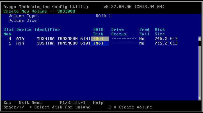
3. On the screen as shown in Figure 47, navigate to a drive, and then press the space bar to select the drive. [Yes] indicates that the drive has been selected for the RAID array. Then, press C.
Figure 47 Selecting the target drives
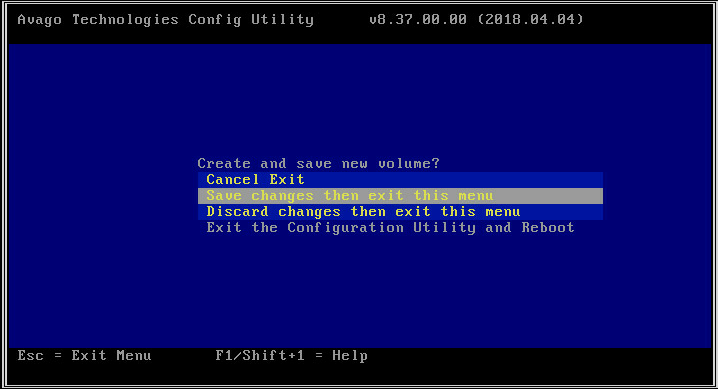
4. On the screen as shown in Figure 48, select Save changes then exit this menu and press Enter.
Figure 48 Save the controller configuration
Configuring hot spare drives
1. On the storage controller configuration screen as shown in Figure 49, select RAID Properties and press Enter.
Figure 49 Storage controller configuration screen

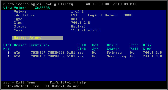
2. On the screen as shown in Figure 50, select Manage Volume and press Enter. For more information about the parameters, see Table 4.
Figure 50 Selecting Manage Volume
|
Parameter |
Description |
|
Volume |
RAID serial number. |
|
Identifier |
RAID identifier. |
|
Type |
RAID level. |
|
Status |
Current RAID status. |
|
Task |
Current RAID task. No background task is in progress for the RAID if this field displays None. |
|
Manage Volume |
You can select this item and press Enter to manage the RAID. |
|
Alt+N |
If two RAID arrays exist, you can press Alt+N to switch the RAID array for information displaying. |
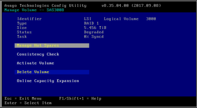
3. On the screen as shown in Figure 51, select Manage Hot Spares and press Enter.
Figure 51 Selecting Manage Hot Spares
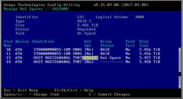
4. On the screen as shown in Figure 52, navigate to a drive, and then press the space bar to select the drive. [Yes] indicates that the drive has been selected. Then, press C.
Figure 52 Selecting the target drives
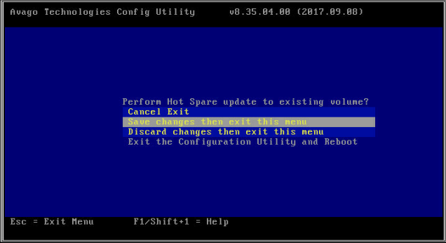
5. On the screen as shown in Figure 53, select Save changes then exit this menu and press Enter.
Figure 53 Saving the controller configuration
Deleting a RAID array
1. On the storage controller configuration screen as shown in Figure 54, select RAID Properties and press Enter.
Figure 54 Storage controller configuration screen

2. On the screen as shown in Table 5, select Manage Volume and press Enter.
Table 5 Selecting Manage Volume

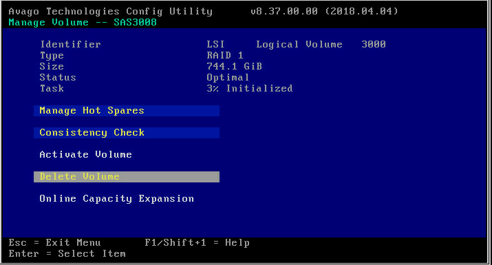
3. On the screen as shown in Figure 55, select Delete Volume, press Enter, and then press Y to delete the array.
Figure 55 Deleting the target array
Running consistency check
This feature enables you to check the consistency and validity of data redundancy for RAID 1, 10, and 1E.
To run consistency check:
1. On the storage controller configuration screen as shown in Figure 56, select RAID Properties and press Enter.
Figure 56 Storage controller configuration screen

2. On the screen as shown in Figure 57, select Manage Volume and press Enter.
Figure 57 Selecting Manage Volume
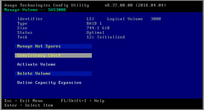
3. On the screen as shown in Table 6, select Consistency Check, press Enter, and then press Y.
Table 6 Selecting Consistency Check
Viewing drive properties
1. On the storage controller configuration screen as shown in Figure 58, select SAS Topology and press Enter.
Figure 58 Storage controller configuration screen
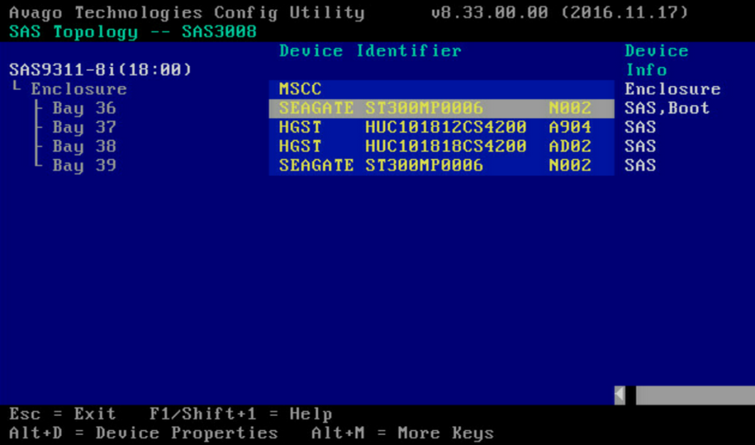
2. On the screen as shown in Figure 59, select the physical drive you want to view and press Alt+D. For more information about the parameters, see Table 7.
Figure 59 Selecting a physical drive
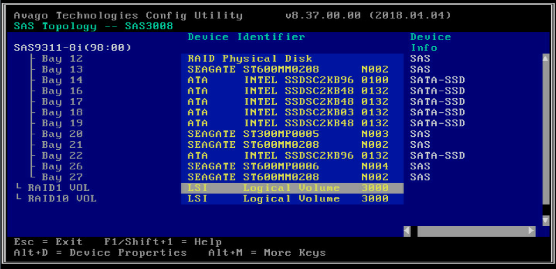
Table 7 SAS Topology parameters
|
Parameter |
Description |
|
Device Info |
Device information. |
|
RAID VOL |
Number of RAID arrays for the controller. A maximum of 2 RAID arrays are supported. The storage controller supports multiple RAID modes. This field varies by RAID level and might display value such as RAID1 VOL or RAID10 VOL. |
|
Alt+D |
Displays the details if you select a drive that is highlighted on the screen. |
|
Alt+M |
Displays more keyboard shortcuts on the SAS Topology screen. |
3. View properties of the drive on the screen as shown in Figure 60.

Locating drives
1. On the storage controller configuration screen as shown in Figure 61, select SAS Topology and press Enter.
Figure 61 Storage controller configuration screen

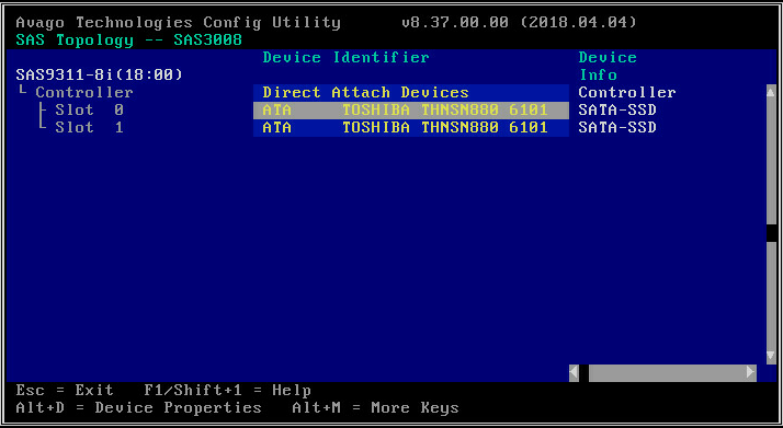
2. On the screen as shown in Figure 62, select the physical drive you want to locate and press Enter to turn on the drive LED on the drive backplane.
Figure 62 Selecting a physical drive

Clearing RAID information or verifying drives
1. On the storage controller configuration screen as shown in Figure 63, select SAS Topology and press Enter.
Figure 63 Storage controller configuration screen

2. On the screen as shown in Figure 64, select the physical drive you want to locate and press Alt+D.
Figure 64 Selecting a physical drive
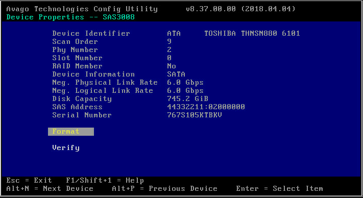
3. On the screen as shown in Figure 65, select Verify or Format as needed, and then press Enter.
Figure 65 Verifying or formatting the physical drive
Setting advanced controller properties
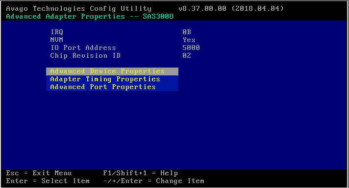
1. On the storage controller configuration screen as shown in Figure 66, select Advanced Adapter Properties and press Enter.
Figure 66 Storage controller configuration screen

2. On the screen as shown in Figure 67, select Advanced Device Properties and press Enter.
Figure 67 Selecting Advanced Device Properties
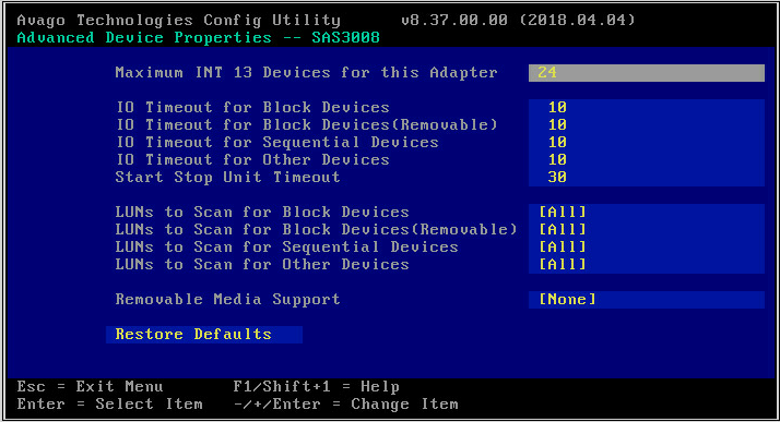
3. Change the advanced properties of the controller on the screen as shown in Figure 68.
Figure 68 Advanced controller properties screen
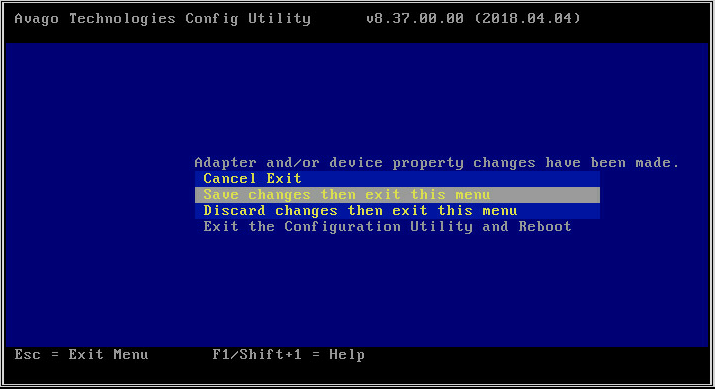
4. Keep pressing Esc till you enter the screen as shown in Figure 69. Select Save changes then exit this menu and press Enter to save the controller configuration.
The change takes effect at next startup.
Figure 69 Saving the controller configuration
Configuring boot options
1. On the storage controller configuration screen as shown in Figure 70, select SAS Topology and then press Enter.
Figure 70 Storage controller configuration screen

2. On the screen as shown in Figure 71, select the target drive and then press Alt+B to specify the drive as the boot device in legacy mode.
Figure 71 Configuring the boot device
3. To display more keyboard shortcuts on the SAS Topology screen, press Alt+M. For more information about keyboard shortcuts, see Table 8.
Figure 72 Displaying more keyboard shortcuts
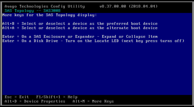
Table 8 Keyboard shortcut parameters
|
Parameter |
Description |
|
Alt+A |
Configure or cancel a selected device as the secondary boot option. The key changes to Boot in Device Info if the operation succeeds. |
|
Alt+B |
Configure or cancel a selected device as the first boot option. The key changes to Alt in Device Info if the operation succeeds. |
|
Enter |
· If you select a drive adapter or RAID, press Enter to display collapsed items. · If you select a drive, press Enter to turn on the Fault/UID LED. |
4. To cancel a specified boot device, select the drive and then press Alt+B.
5. Press Esc until you enter the screen as shown in Figure 73, select Save changes then exit this menu and then press Enter to save the configuration.
The boot option configuration takes effect at next startup.
Figure 73 Saving storage controller configuration

