- Table of Contents
-
- H3C CR19000-8 Core Router Installation Guide-6W103
- 00-Preface
- 01-Chapter 1 Preparing for Installation
- 02-Chapter 2 Installing the Router
- 03-Chapter 3 Installing Power Supplies
- 04-Chapter 4 Installing Removable Components
- 05-Chapter 5 Connecting Cables
- 06-Chapter 6 Verifying the Installation
- 07-Chapter 7 Accessing the Router
- 08-Chapter 8 Replacement Procedures
- 09-Chapter 9 Troubleshooting
- 10-Appendix A Engineering Labels
- 11-Appendix B Cable Management
- 12-Appendix C Repackaging the Router
| Title | Size | Download |
|---|---|---|
| 12-Appendix C Repackaging the Router | 1.74 MB |
12 Appendix C Repacking the router
Removing cables from the router
Removing the twisted pair cables and optical fibers
Repacking the fabric module slot filler panels
Removing the chassis from the rack
12 Appendix C Repacking the router
This chapter describes how to repack the router chassis, power supplies, and modules.
Removing cables from the router
Before repacking the router, remove all cables such as the power cords, console cable, twisted pair cables, optical fibers, and grounding cable from the router.
Removing the power cords
1. Switch off the circuit breakers at the input end of all power cords.
2. Wear an ESD wrist strap, and make sure it makes good skin contact and is reliably grounded.
3. Remove a power cord.
¡ For an AC power cord, remove the cable tie, and then remove the power cord connector from the power supply.
¡ For a DC power cord, loosen the screw on the power cord connector, and then remove the connector from the power supply.
4. Perform the same steps to remove the other power cords.
Removing the console cable
1. Pull the RJ-45 connector of the console cable out from the console port of the router.
2. Pull the DB-9 connector of the console cable out from the serial port of the PC or the terminal.
Removing the grounding cable
1. Loosen the two screws at the grounding holes in the chassis, and then remove the grounding cable from the chassis.
2. Use a wrench to loosen the hex nut on the grounding post of the grounding strip, and remove the other end of the grounding cable (with a ring terminal) from the grounding post.
Removing the twisted pair cables and optical fibers
You must remove all twisted pair cables and optical fibers from the ports on the router.
|
|
NOTE: After pulling out an optical fiber from a transceiver module, cover the connector of the optical fiber with a dust cap to keep the connector clean. |
Repacking the FRUs
Repacking power supplies
|
|
CAUTION: To avoid device damage and bodily injury, switch off the circuit breakers at the input ends of all power cords and remove all the power cords before removing power supplies. |
1. Prepare the original packing materials, including the anti-static bag, foam cushion, and packing box for a power supply. Make sure these packing materials are clean, dry, and not damaged.
2. Remove the power supply from the chassis.
For the power supply removal procedure, see "Replacement procedures."
3. Put the removed power supply into the anti-static bag.
4. Place the foam cushion over the power supply.
5. Place the power supply and the foam cushion in the packing box, and seal the box with tape.
6. Perform the same steps to repack the other power supplies.
Repacking the modules
1. Prepare the original packing materials, including the anti-static shielding bag, foam cushion, and packing box, for a module. Make sure these packing materials are clean, dry, and not damaged.
2. Remove the transceiver modules from the modules.
If no transceiver module is installed, skip this step.
For information about how to remove a transceiver module, see "Replacement procedures."
3. Remove a module from the chassis.
If a filler panel is provided for the module slot, install the filler panel in the slot after you remove the chassis from the rack.
For information about how to remove a module and install a filler panel, see "Replacement procedures."
4. Put the removed module into an anti-static bag.
For a module provided with a metal protection box, install the metal protection box for it before putting it into an anti-static bag.
5. Place the foam cushion over the module.
6. Put the module and the foam cushion into the box, and seal the box with tape.
7. Perform the same steps to repack the other modules.
Repacking the fabric module slot filler panels
1. Prepare the original packing materials, including the packing bag, foam cushion, and packing box, for a fabric module slot filler panel. Make sure these packing materials are clean, dry, and not damaged.
2. Remove the fabric module slot filler panel.
3. Place the removed fabric module slot filler panel in the packing bag.
4. Place the foam cushion over the packing bag.
5. Place the fabric module slot filler panel and the foam cushion in the packing box, and seal the box with tape.
6. Perform the same steps to repack the other fabric module slot filler panels.
Repacking the router chassis
Removing the chassis from the rack
The router is heavy. As a best practice, use a mechanical lift to move the router.
To remove the chassis from the rack:
1. Prepare the pallet, carton, and packing bag of the chassis. Make sure they are clean, dry, and not damaged.
2. Place the pallet at a location where you can move the chassis easily.
3. Remove the air filter and top hood from the chassis.
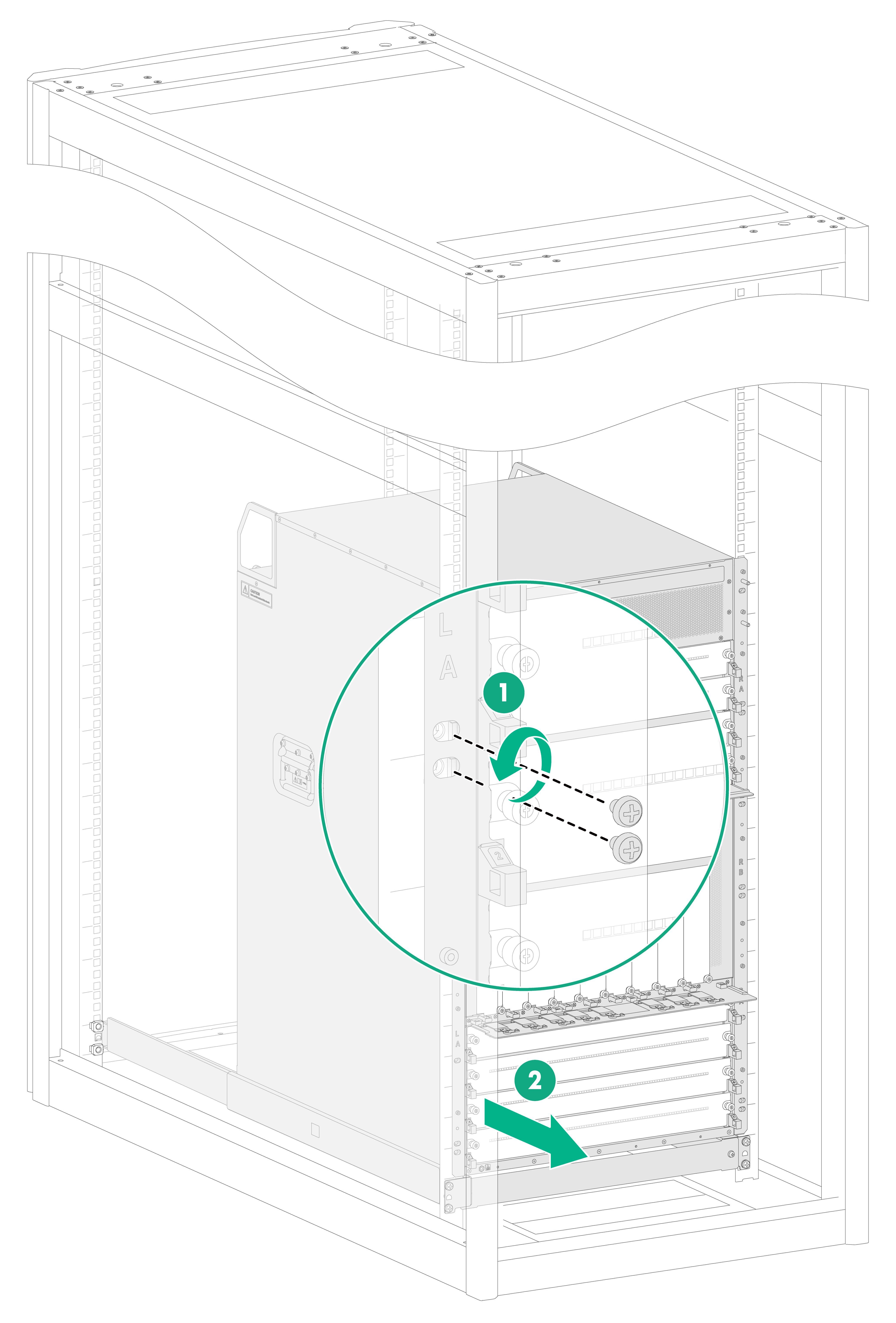
4. As shown by callout 1 in Figure12-1, use a Phillips screwdriver to loosen the screws that attach the mounting brackets to the rack.
5. As shown by callout 2 in Figure12-1, use a minimum of four people to slide the chassis out of the rack along the slide rails. When most part of the chassis is removed from the slide rails, lift up the chassis by holding the chassis handles to completely remove the chassis from the rack.
6. Place the chassis onto the pallet.
Figure12-1 Removing the router from the rack
Repacking the router chassis
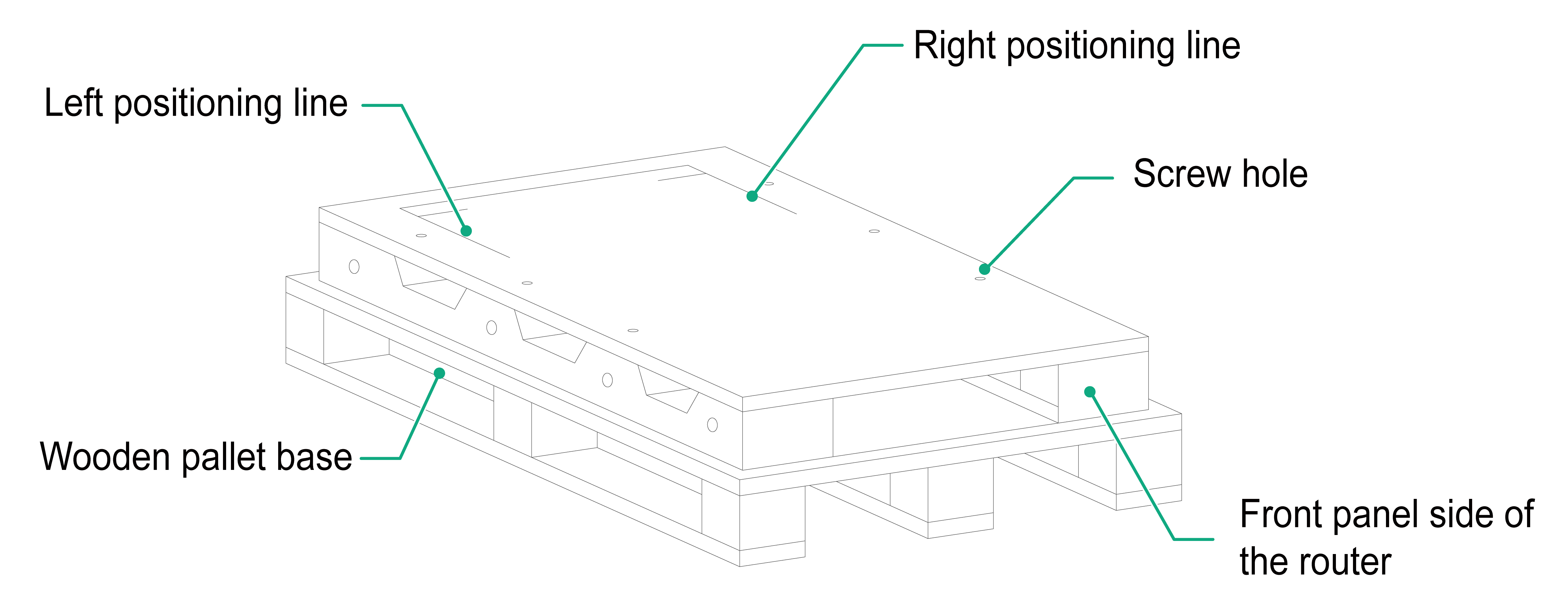
1. Move the chassis so that the left and right edges of the chassis bottom are aligned with the left and right positioning lines respectively on the pallet. See Figure12-2 for the pallet.
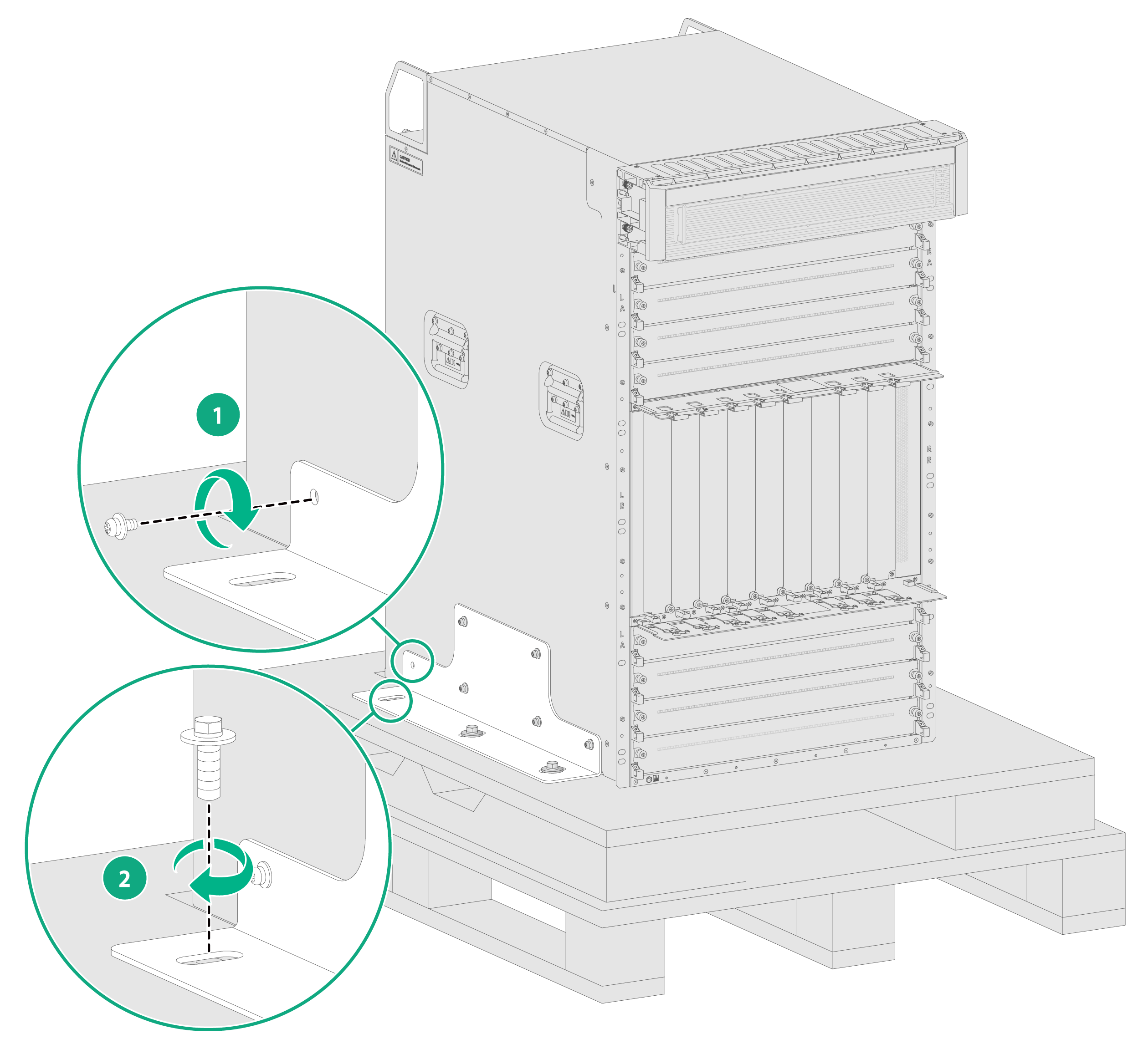
2. Use screws to attach the L-type brackets to the chassis, as shown by callout 1 in Figure12-3.
3. Move the chassis so that the mounting holes in the pallet ear of the L-type brackets align with the mounting holes in the pallet. Use screws to attach the L-type brackets to the pallet, as shown by callout 2 in Figure12-3.
Figure12-3 Attaching the L-type brackets to the pallet
4. Place the packing bag over the chassis, and then tape the bag to the plastic film on the pallet.
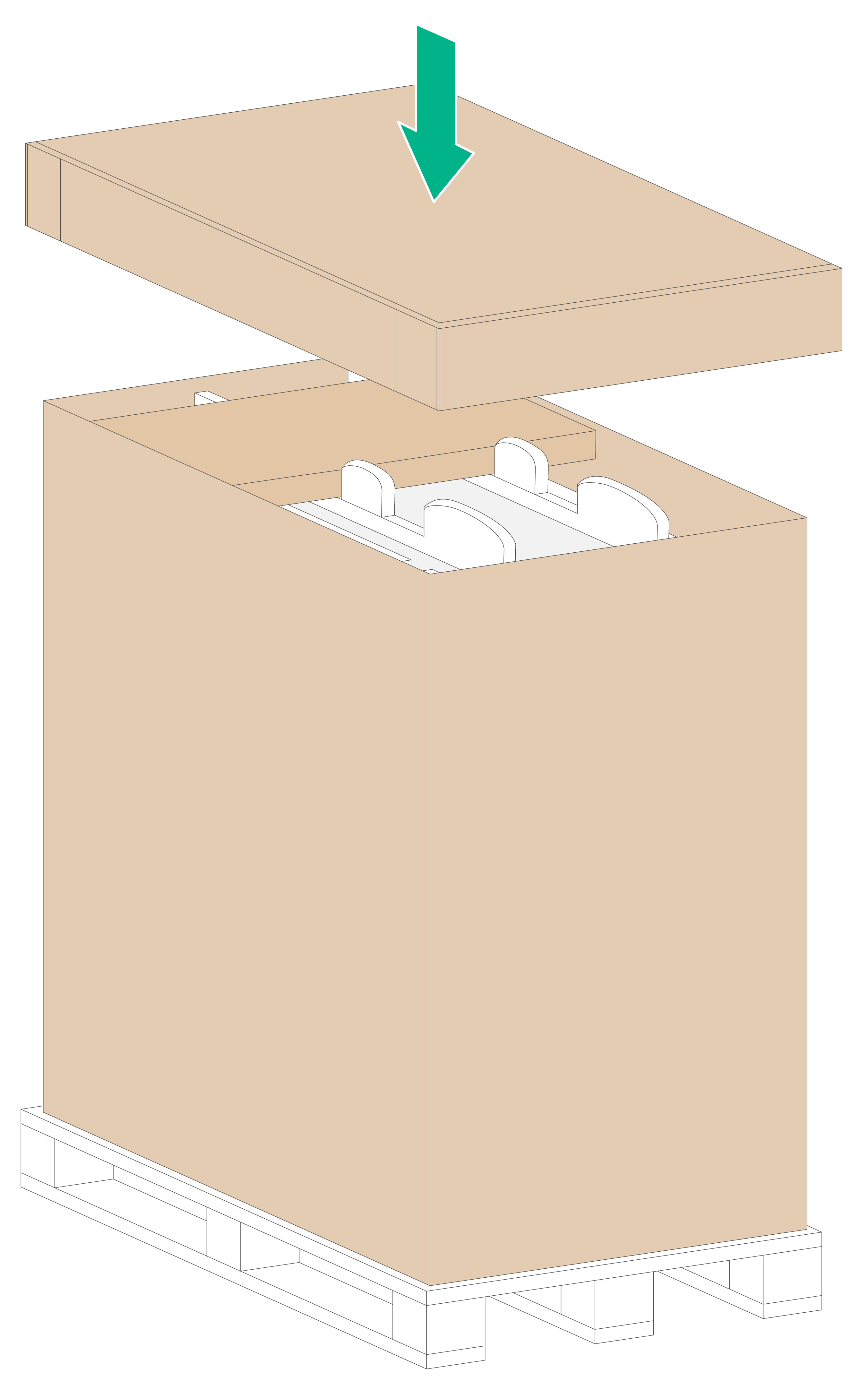
5. Align the carton's narrow side that has printings with the front panel of the chassis and then place the carton over the chassis. Erect one paper angle bead at each corner of the carton, as shown in Figure12-4.
Figure12-4 Placing the carton over the router
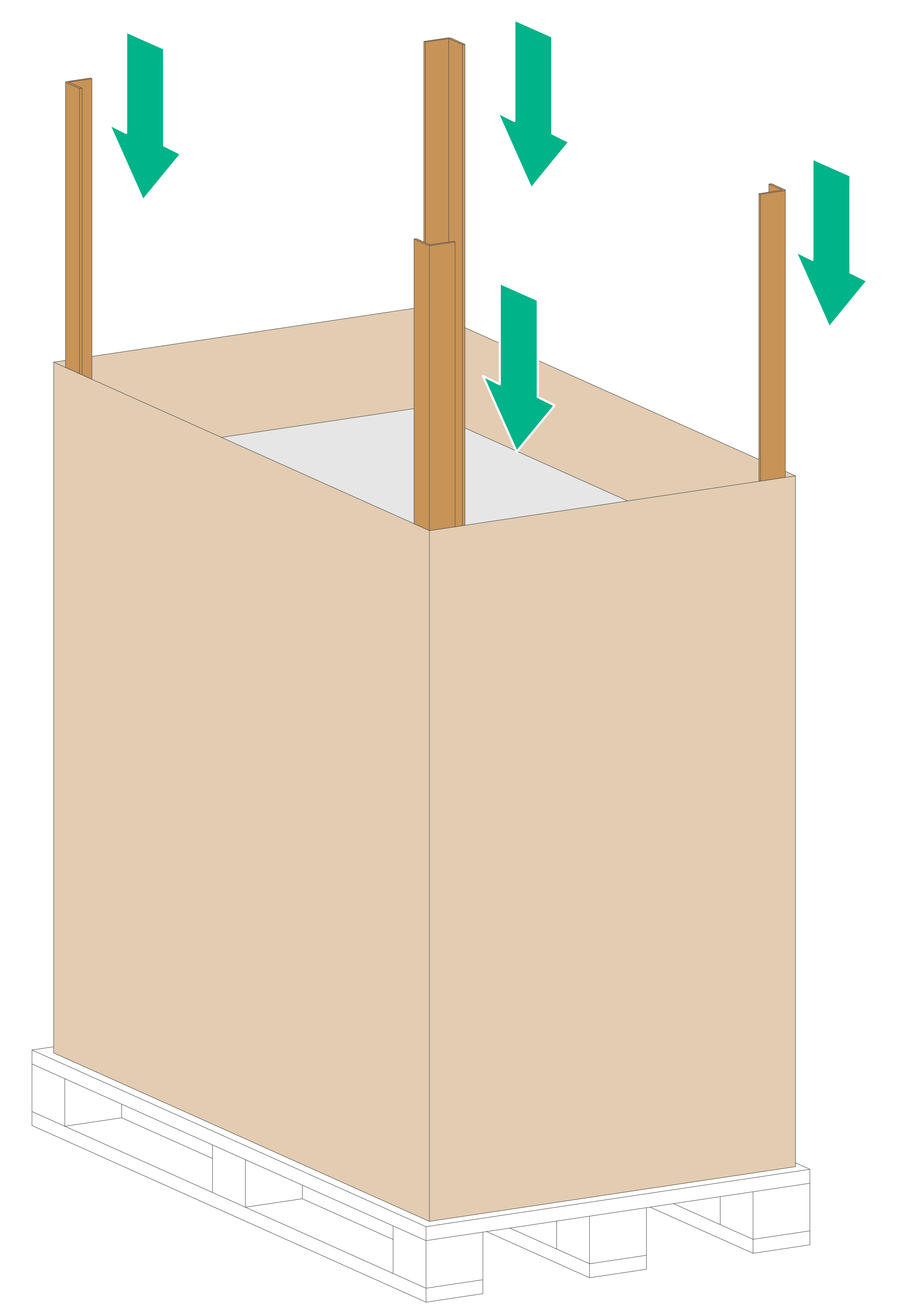
6. Put the foam cushion onto the chassis top, and make sure the mounting brackets seat into the internal notches of the foam cushion.
7. Fit the accessory box into the rear notch of the foam cushion. Then close the top cover of the carton.
Figure12-5 Putting the foam cusion and carton top cover in place