- Table of Contents
-
- H3C CR19000-8 Core Router Installation Guide-6W103
- 00-Preface
- 01-Chapter 1 Preparing for Installation
- 02-Chapter 2 Installing the Router
- 03-Chapter 3 Installing Power Supplies
- 04-Chapter 4 Installing Removable Components
- 05-Chapter 5 Connecting Cables
- 06-Chapter 6 Verifying the Installation
- 07-Chapter 7 Accessing the Router
- 08-Chapter 8 Replacement Procedures
- 09-Chapter 9 Troubleshooting
- 10-Appendix A Engineering Labels
- 11-Appendix B Cable Management
- 12-Appendix C Repackaging the Router
- Related Documents
-
| Title | Size | Download |
|---|---|---|
| 08-Chapter 8 Replacement Procedures | 8.98 MB |
Contents
Replacing an MPU or a fabric module
Replacing an interface module that uses detachable ejector levers
Replacing an interface module with ejector levers
Replacing an interface subcard
Replacing a QSFP+ optical fiber for a multi-chassis fabric module
8 Replacement procedures
|
|
WARNING! · When replacing removable components while the router is operating, ensure electricity safety. · To avoid bodily injury and device damage, follow the replacement procedure strictly to replace a component. · Long-time exposure to strong air flow might cause discomfort. To avoid this hazard, do not stand close to the air outlet vents while the router is operating. If you must be next to the router on the air outlet vent side for an extended period, avoid the air flow or take other protective measures. |
The router uses a modular architecture, and supports removable components. You can replace a removable component when the router is operating.
Replacing a module
|
|
CAUTION: If you are not to install a new module in a slot after removing the old one, install a filler panel in the slot for adequate heat dissipation and dust prevention. |
Unless otherwise stated, MPUs, interface modules, interface subcards, and fabric modules are collectively referred to as "modules" in this document.
Replacing an MPU or a fabric module
|
|
CAUTION: · The router supports active/standby MPU switchover when you install two MPUs for the router. Make sure the active and standby MPUs are the same model. · Before replacing a fabric module, press the OFL button on the module. The RUN LED will flash red for 3 seconds. After the RUN LED is off, you can remove the module. |
The replacement procedure is similar for MPUs and fabric modules.
To replace an MPU or a fabric module:
1. Remove the cables from the MPU or fabric module.
2. Prepare an antistatic mat to place the removed MPU or fabric module.
3. Wear an ESD wrist strap. Make sure the wrist strap makes good skin contact and is reliably grounded.
4. Use a Phillips screwdriver to loosen the captive screws on the MPU or fabric module.
5. Open the ejector levers on the module and then pull the module part way out of the slot.
6. Supporting the module bottom with the left hand, slowly pull the module out of the slot along the guide rails with the right hand.
7. Place the removed module on the antistatic mat.
8. Install a new MPU or fabric module. For the installation procedure, see "Installing MPUs" or "Installing fabric modules."

Replacing an interface module that uses detachable ejector levers
|
|
CAUTION: · Put the detachable ejector lever back to its holder after use and then attach them to the chassis or cabinet for future use. · The ejector lever holder is magnetic. Beware of electromagnetic interference. · Do not use only one detachable ejector lever to install or remove an interface module. · Do not hold detachable ejector levers to lift an interface module. |
To replace an interface module that uses detachable ejector levers:
1. Remove the cables from the interface module.
2. Prepare an antistatic mat to place the removed interface module.
3. Wear an ESD wrist strap. Make sure the wrist strap makes good skin contact and is reliably grounded.
4. Use a Phillips screwdriver to loosen the captive screws on the interface module.
5. Attach the ejector lever holders to the cabinet or chassis and then remove the ejector levers from the holders.
6. Identify the "L" and "R" marks on the ejector levers and attach them to left and right ejector lever retainers of the interface module, respectively, with the lettering on the ejector levers facing upward. See callout 1 in Figure8-2.
7. Open the ejector levers on the interface module and then pull the interface module part way out of the slot, as shown by callout 2 in Figure8-2.
Figure8-2 Opening a detachable ejector lever

8. Detach the ejector levers from the interface module and then attach the ejector levers to the ejector lever holder.
Keep the ejector levers secure for future use.
9. Supporting the interface module bottom with one hand, slowly pull the interface module out of the slot along the guide rails with the other hand.
10. Place the removed interface module on the antistatic mat.
11. Install a new interface module. For the installation procedure, see "Installing an interface module that uses detachable ejector levers."
Figure8-3 Removing an interface module

Replacing an interface module with ejector levers
1. Remove the cables from the interface module.
2. Prepare an antistatic mat to place the removed interface module.
3. Wear an ESD wrist strap. Make sure the wrist strap makes good skin contact and is reliably grounded.
4. Use a Phillips screwdriver to loosen the captive screws on the interface module.
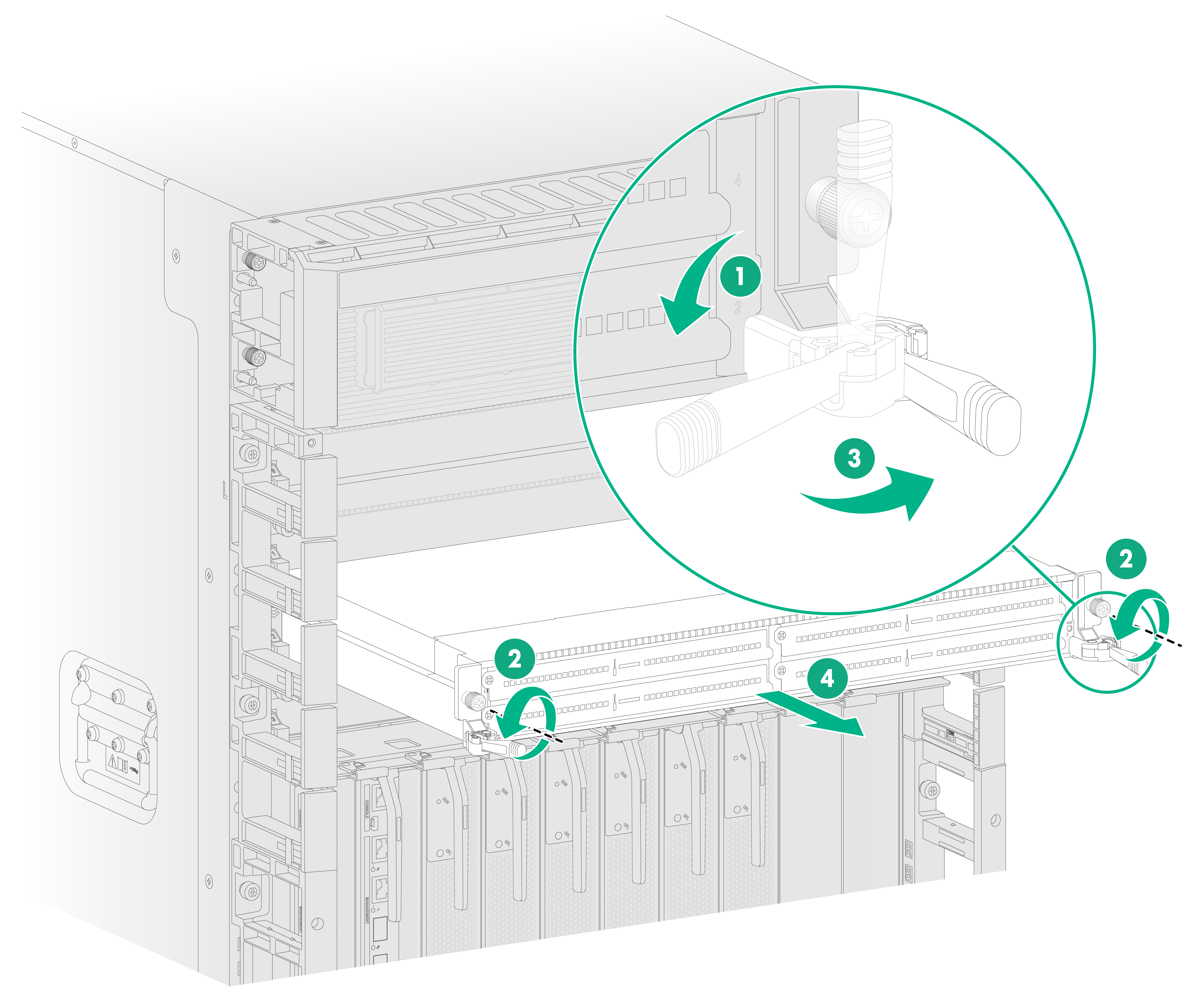
5. Fully open the ejector levers on the interface module and then pull the interface module part way out of the slot.
6. Supporting the interface module bottom with one hand, slowly pull the interface module out of the slot along the guide rails with the other hand.
7. Place the removed interface module on the antistatic mat.
8. Install a new interface module in the slot. For the installation procedure, see "Installing an interface module with ejector levers."
Figure8-4 Removing an interface module with ejector levers
Replacing an interface subcard
|
|
IMPORTANT: · If you are not to install a new interface subcard after removing the old one, install a filler panel in the slot. · When installing a filler panel, orient it with the blade of the screwdriver image on it facing upwards. First insert the filler panel right side into the slot, and then push the left side into the slot. |
To install an interface subcard:
1. Remove the cables from the interface subcard.
2. Prepare an antistatic mat to place the removed interface subcard.
3. Wear an ESD wrist strap. Make sure the wrist strap makes good skin contact and is reliably grounded.
4. Use a Phillips screwdriver to loosen the captive screws on the interface subcard.
5. Open the ejector levers on the interface subcard and then pull the interface subcard out of the slot along the guide rails.
6. Place the removed interface subcard on the antistatic mat.
7. Install a new interface subcard. For the installation procedure, see "Installing interface subcards."
Figure8-5 Removing an interface subcard

Replacing transceiver modules
|
|
WARNING! Disconnected optical fibers or transceiver modules might emit invisible laser light. Do not stare into beams or view directly with optical instruments when the router is operating. |
|
|
CAUTION: · Do not touch the golden plating on a transceiver module. · Make sure the transceiver modules at the two ends of an optical fiber are the same model. |
To replace a transceiver module and optical fiber:
1. Wear an ESD wrist strap. Make sure the wrist strap makes good skin contact and is reliably grounded.
2. Remove the optical fibers from the transceiver module.
¡ To remove the optical fibers with an LC connector, press the clip on the connector to pull the LC connector out of the port, as shown in Figure8-6.
¡ To remove the optical fiber with an MPO connector, hold the front end of the MPO connector to pull it out of the port, as shown in Figure8-7.
3. Pull down the bail latch on the module to the horizontal position (skip this step for QSFP+/QSFP28 transceiver modules with a plastic bail latch). Hold the bail latch to pull the module horizontally and slowly out of the port.
If the interface module is densely populated with transceiver modules, use tweezers to pull the module out.
4. Insert the dust plugs into the transceiver module and put it into its original packing materials.
5. Install a new transceiver module in the port. For the installation procedure, see "Installing transceiver modules and optical fibers."
If you are not to install a new transceiver module in the port, insert a dust plug into the port.
Figure8-6 Removing a transceiver module (LC port)

Figure8-7 Removing a transceiver module (MPO port)

Replacing a QSFP+ optical fiber for a multi-chassis fabric module
1. Wear an ESD wrist strap and make sure it makes good skin contact and is reliably grounded.
2. Hold the pull tab of the connector and remove the optical fiber from the QSFP+ transceiver module.
3. Connect a new QSFP+ optical fiber. For the installation procedure, see "Connecting a QSFP+ optical fiber."
If you are not to install a QSFP+ optical fiber in the port, insert the dust plug into the fiber port.
Figure8-8 Removing a QSFP+ optical fiber

Replacing a fan tray
|
|
WARNING! · Ensure electricity safety when you hot swap a fan tray. · To avoid bodily injury, do not touch the spinning fans when you replace the fan tray. · When you hot swap a fan tray, the fan rotation speed of the remaining fan trays automatically increases and the fan trays make louder noise. Take protection measures such as wearing an earmuff or earplug. In addition, make good preparations before the hot swapping to minimize the operation time. |
|
|
CAUTION: · When a fan tray fails, replace the faulty fan tray immediately. · To prevent dust from entering the device, keep the old fan tray installed in the chassis until a new fan tray is ready to be installed. · Before hot swapping a fan tray, make sure the remaining fan trays can provide sufficient cooling for the router. · If multiple fan trays fail, do not remove the fan trays at the same time. Replace the fan trays one after another and finish replacing a fan tray within 3 minutes. |
To replace a fan tray:
1. Prepare an antistatic mat to place the removed fan tray.
2. Wear an ESD wrist strap. Make sure the wrist strap makes good skin contact and is reliably grounded.
3. Loosen the captive screws on the fan tray.
4. Holding the handles on the fan tray, pull the fan tray part way out of the slot. After the fans stop rotating, pull the fan tray out from the chassis.
5. Place the removed fan tray on the antistatic mat.
6. Install a new fan tray. For the installation procedure, see "Installing fan trays."
Figure8-9 Removing a fan tray

Replacing a power supply
|
|
WARNING! · Provide a circuit breaker for each power supply. Before replacing a power supply, turn off the circuit breaker for it. · To reinstall the removed power supply in the chassis, wait until the status LED on it is off. · To avoid being hurt, allow a power supply to cool before removing it. |
To avoid device damage and bodily injury, strictly follow the procedures shown in Figure8-10 and Figure8-11 to remove and install a power supply, respectively.
Figure8-10 Power supply removal procedure
![]()
Figure8-11 Power supply installation procedure
![]()
To replace a power supply:
1. Prepare an antistatic mat to place the removed power supply.
2. Turn off the circuit breaker.
3. Wear an ESD wrist strap, and make sure it makes good skin contact and is reliably grounded.
4. Remove the cable tie, and then remove the power cord connector from the power supply.
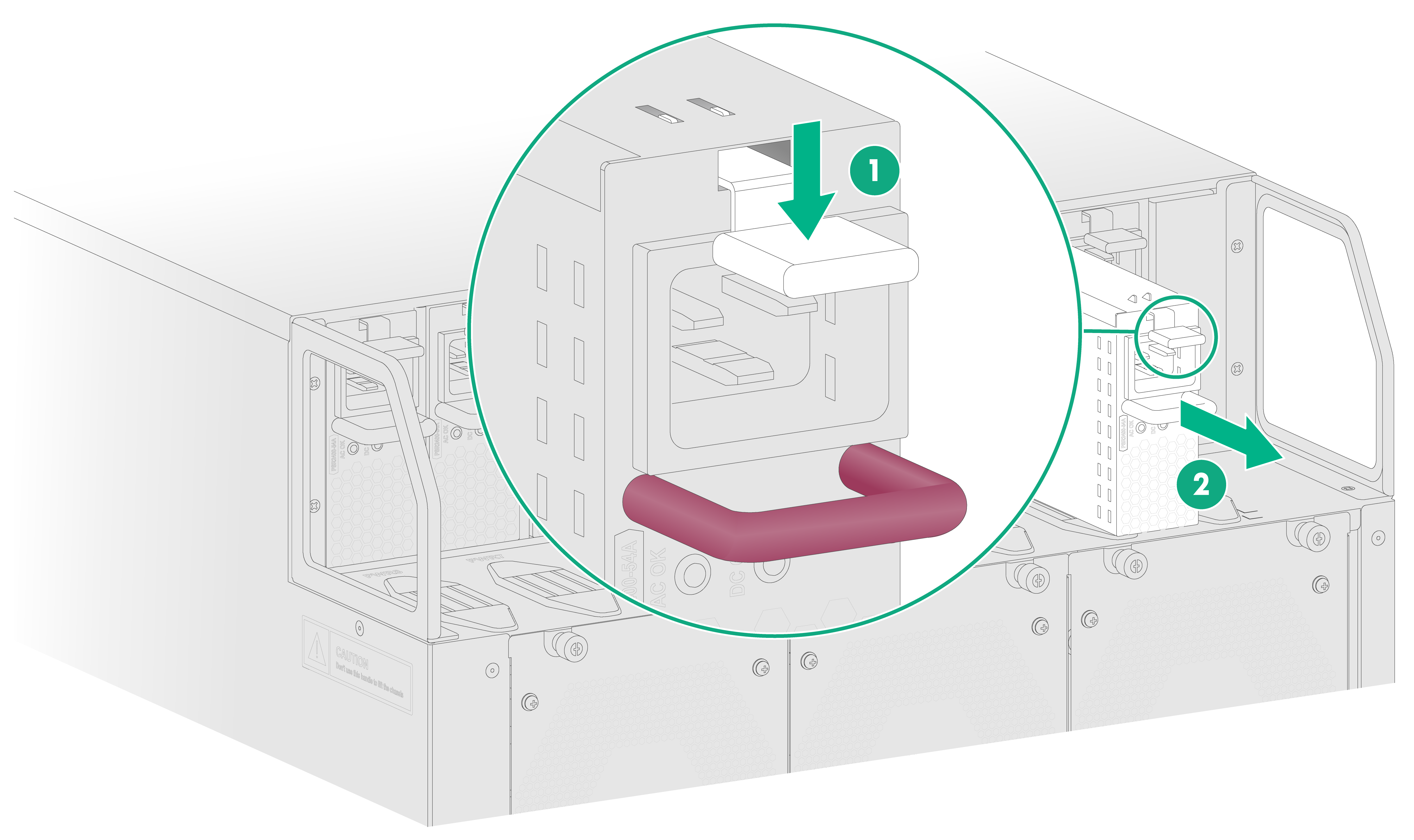
5. Press the latch on the power supply towards the handle direction and pull the power supply part way out of the slot.
6. Holding the power supply handle with one hand and supporting the power supply bottom with the other, pull the power supply slowly out of the slot.
7. Place the removed power supply on the antistatic mat.
8. Install a new power supply. For information about the power supply installation procedure, see "Installing power supplies."
Figure8-12 Removing a power supply (AC power supply)