- Table of Contents
-
- H3C CR19000-8 Core Router Installation Guide-6W103
- 00-Preface
- 01-Chapter 1 Preparing for Installation
- 02-Chapter 2 Installing the Router
- 03-Chapter 3 Installing Power Supplies
- 04-Chapter 4 Installing Removable Components
- 05-Chapter 5 Connecting Cables
- 06-Chapter 6 Verifying the Installation
- 07-Chapter 7 Accessing the Router
- 08-Chapter 8 Replacement Procedures
- 09-Chapter 9 Troubleshooting
- 10-Appendix A Engineering Labels
- 11-Appendix B Cable Management
- 12-Appendix C Repackaging the Router
- Related Documents
-
| Title | Size | Download |
|---|---|---|
| 03-Chapter 3 Installing Power Supplies | 4.77 MB |
3 Installing power supplies
Installing DC power supplies
Available DC power supplies
The PSR2400-54D DC power supply is available for the router. Table3-1 describes the PSR2400-54D DC power supply specifications.
Table3-1 PSR2400-54D DC power supply specifications
|
Item |
Specification |
|
Rated input voltage |
–48 to –60 VDC |
|
Input voltage range |
–40 to –72 VDC |
|
Max input current |
80 A |
|
Rated output voltage |
54 VDC |
|
Max. output current |
44.5 A |
|
Max. output power |
2400 W |
DC power supply configuration guidelines
Determine the number of DC power supplies based on the system power consumption and the DC power supply configuration based on the power input mode.
· Make sure the total output power of the power supplies is greater than the system power consumption (with a 20% power surplus as a best practice).
· As a best practice, configure N+M (M ≥ 1) DC power supply redundancy. Make sure N+M is not larger than the total number of power supply slots.
N is the number of DC power supplies.
· Provide a circuit breaker for power input of each DC power supply. Make sure each circuit breaker has a current rating not less than 100 A.
Installing a DC power supply
1. Wear an ESD wrist strap and make sure the strap makes good skin contact and is reliably grounded.
2. Remove the filler panel from the target power supply slot.
Put your forefinger into the hole of the filler panel to hold and pull out the filler panel along the guide rails as shown in Figure3-1.
Figure3-1 Removing a filler panel

3. Correctly orient the power supply with the latch above the handle.
4. Align the power supply with the power supply slot. Then slide the power supply along the guide rails into the slot until the latch locks the power supply in place.
Figure3-2 Installing a DC power supply
Connecting a DC power cord
|
|
CAUTION: Before you connect a power cord, turn off the circuit breakers for both positive and negative inputs. |
To connect a DC power cord:
1. Connect the DC power cord connectors to the DC input receptacles on the DC power supply.
2. Fasten the screw on the connectors to secure the connectors to the receptacles.
3. Connect the other ends of the power cord to a DC input terminal block, with the negative wire (–) to the negative terminal (–) and the positive wire (+) to the positive terminal (+).
Figure3-3 Connecting a DC power cord

Installing AC power supplies
Available AC power supplies
The PSR2400-54A and PSR3000-54A AC power supplies are available for the router. Table3-2 describes the AC power supply specifications.
Table3-2 AC power supply specifications
|
Item |
PSR2400-54A |
PSR3000-54A |
|
Rated input voltage |
· AC power input: ¡ 100 to 130 VAC @ 60 Hz ¡ 200 to 240 VAC @ 50 Hz · High voltage DC power input: 240 VDC |
· AC power input: ¡ 100 to 130 VAC @ 60 Hz ¡ 200 to 240 VAC @ 50 Hz · High voltage DC power input: 240 VDC |
|
Input voltage range |
· AC power input: 90 to 264 VAC @ 47 to 63 Hz · High voltage DC power input: 190 to 320 VDC |
· AC power input: 90 to 290 VAC @ 47 to 63 Hz · High voltage DC power input: 190 to 320 VDC |
|
Rated input current |
16 A |
16 A |
|
Rated output voltage |
54 VDC |
54 VDC |
|
Max. output current |
44.5 A |
55.6 A |
|
Max. output power |
· 100 to 130 VAC @ 60 Hz: 1200 W · 200 to 240 VAC @ 50 Hz: 2400 W · 240 VDC: 2400 W |
· 100 to 130 VAC @ 60 Hz: 1200 W · 200 to 240 VAC @ 50 Hz: 3000 W · 240 VDC: 3000 W |
AC power supply configuration guidelines
Determine the number of AC power supplies based on the system power consumption and the AC power supply configuration based on the power input mode.
· Make sure the total output power of the power supplies is greater than the system power consumption (with a 20% power surplus as a best practice).
· As a best practice, configure N+N (dual power sources) AC power supply redundancy. Make sure N+N is not larger than the total number of power supply slots.
N is the number of AC power supplies.
· Provide a circuit breaker for power input of each AC power supply. Make sure each circuit breaker has a current rating not less than 20 A.
Installing an AC power supply
1. Wear an ESD wrist strap and make sure the strap makes good skin contact and is reliably grounded.
2. Put your forefinger into the hole of the filler panel and to hold and pull out the filler panel along the guide rails as shown in Figure3-4.
Figure3-4 Removing a filler panel

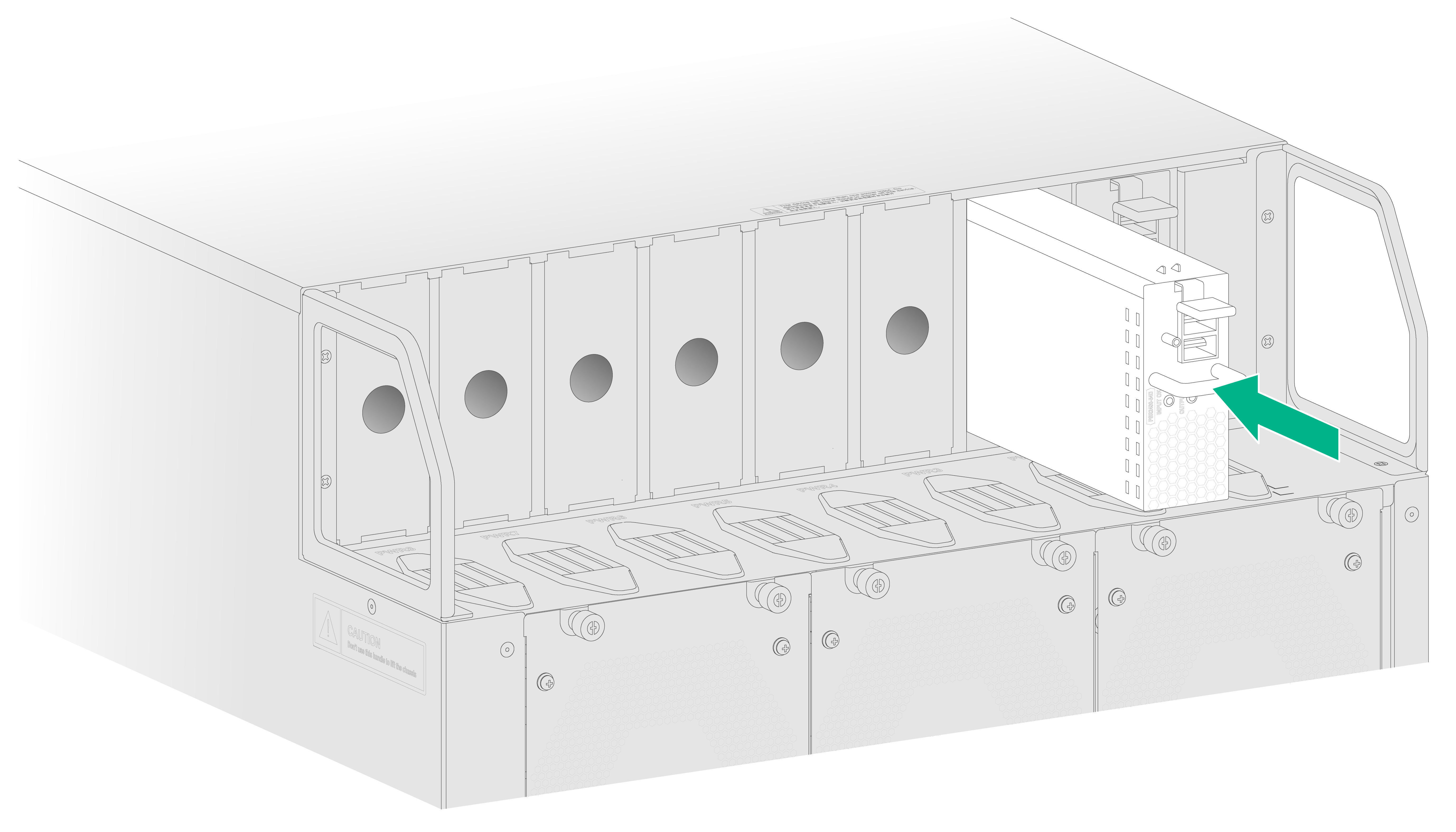
3. Correctly orient the power supply with the latch above the handle.
4. Align the power supply with the power supply slot. Then slide the power supply along the guide rails into the slot until the latch locks the power supply in place.
Figure3-5 Installing an AC power supply

Connecting an AC power cord
|
|
CAUTION: · Before powering on power supplies, finish installing fan trays. · Make sure each power cord has a separate circuit breaker. Before you connect a power cord, turn off the circuit breaker for it. · Use 16A AC power cords with a straight C19 connector for the router. |
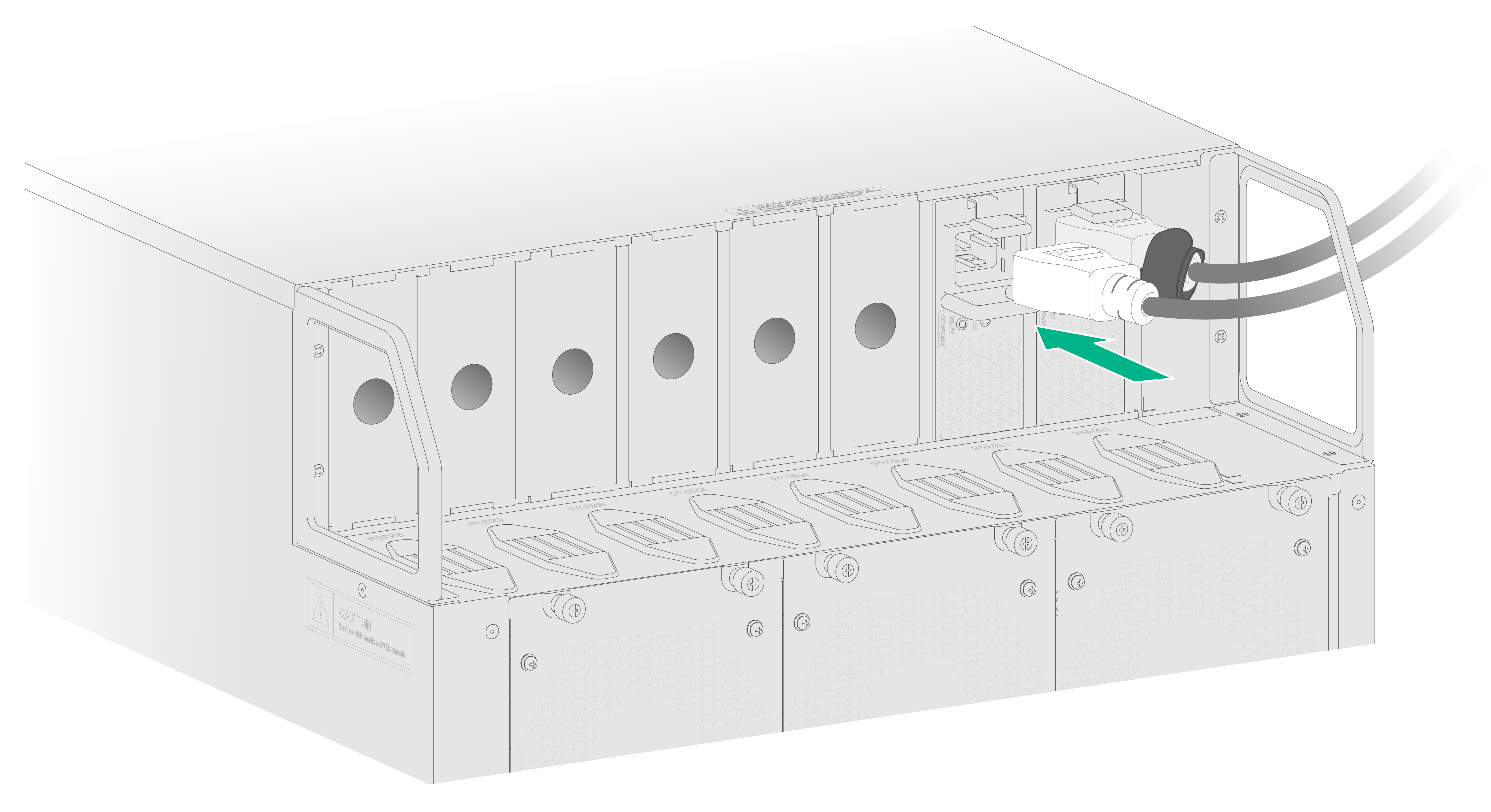
To connect an AC power cord:
1. Connect the female connector of the AC power cord to the AC input receptacle on the AC power supply.
2. Use a Velcro strap to secure AC power cord to the handle of the AC power supply, as shown in Figure3-6.
3. Connect the other end of the power cord to an AC power source.
Figure3-6 Connecting an AC power cord