- Table of Contents
-
- H3C CR19000-8 Core Router Installation Guide-6W103
- 00-Preface
- 01-Chapter 1 Preparing for Installation
- 02-Chapter 2 Installing the Router
- 03-Chapter 3 Installing Power Supplies
- 04-Chapter 4 Installing Removable Components
- 05-Chapter 5 Connecting Cables
- 06-Chapter 6 Verifying the Installation
- 07-Chapter 7 Accessing the Router
- 08-Chapter 8 Replacement Procedures
- 09-Chapter 9 Troubleshooting
- 10-Appendix A Engineering Labels
- 11-Appendix B Cable Management
- 12-Appendix C Repackaging the Router
- Related Documents
-
| Title | Size | Download |
|---|---|---|
| 02-Chapter 2 Installing the Router | 10.44 MB |
Confirming installation preparations
Attaching slide rails to the rack
Removing the top hood and air filter
Installing the top hood and air filter
Installing cable management brackets
2 Installing the router
Confirming installation preparations
Before you install the router, verify that:
· You have read "Preparing for installation" carefully.
· All the requirements described in "Preparing for installation" are met.
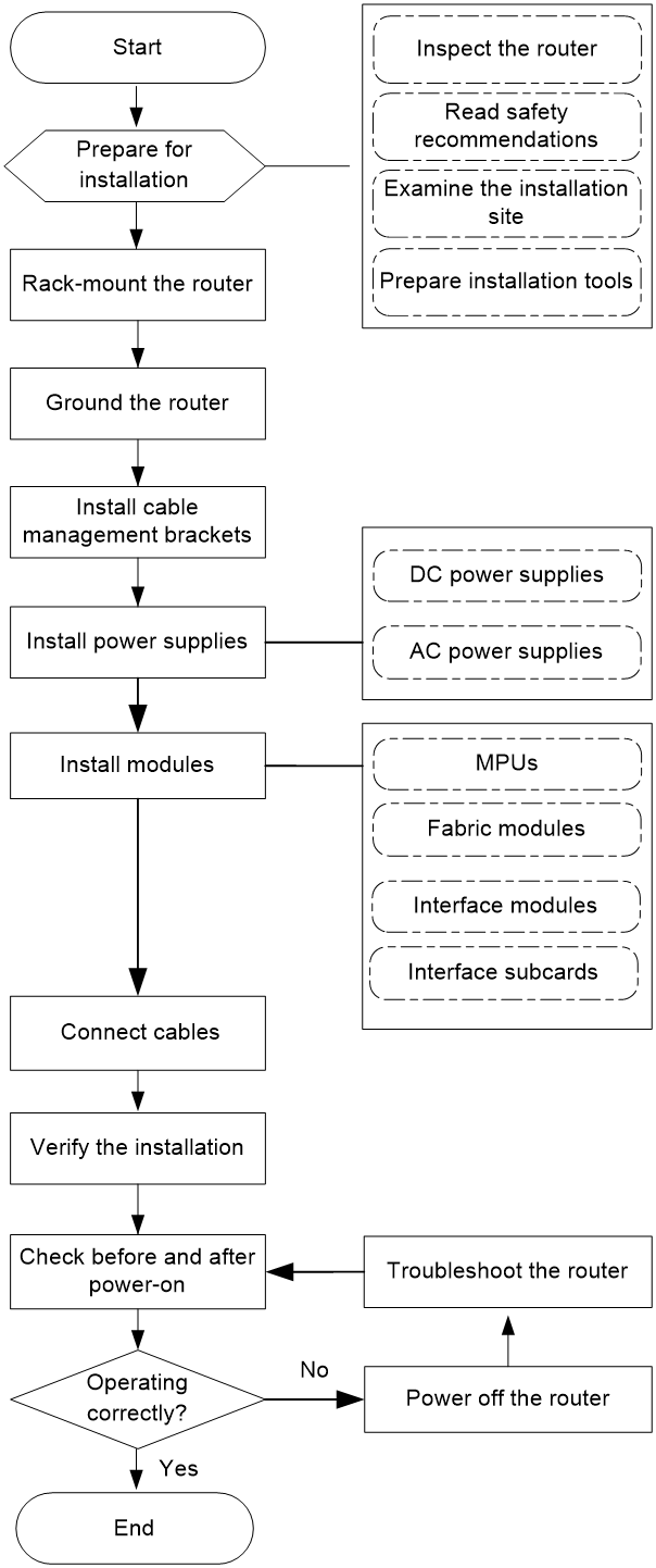
Installation flowchart
Figure2-1 Installation flowchart
Rack-mounting the router
Attaching slide rails to the rack
|
|
CAUTION: The router is heavy. For rack stability, install it at a lowest possible position. |
To rack-mount the router, select and attach slide rails to the rack. See Table2-1 for the slide rail requirements.
Table2-1 Slide rail requirements
|
Router model |
Max. chassis weight (fully configured) |
Applicable slide rails |
||
|
Slide rail model |
Adjustment range |
Occupied space |
||
|
CR19000-8 |
230 kg (507.05 lb) |
LSXM1BSR Applicable to a rack with a depth of 1000 mm (39.37 in) or above. |
630 mm to 900 mm (24.80 in to 35.43 in) |
1 RU |
|
LSTM2KSGD0 Applicable to a rack with a depth of 800 mm (31.50 in) |
500 mm to 800 mm (19.69 in to 31.50 in) |
2 RU |
||
|
LSTM1KSGD0 Applicable to a rack with a depth of 800 mm (31.50 in) |
350 mm to 500 mm (13.78 in to 19.69 in) |
2 RU |
||
For information about installing H3C 1 RU slide rails, see H3C LSXM1BSR 1U Bottom-Support Rails Installation Guide (available at https://www.h3c.com/en/Support/Resource_Center/EN/Routers/Catalog/CR19000/CR19000/).
For more information about installing H3C 2 RU slide rails, see H3C 2RU Slide Rails Installation Guide (available at https://www.h3c.com/en/Support/Resource_Center/EN/Routers/Catalog/CR19000/CR19000/).
When installing slide rails, make sure the load-bearing plane of the slide rails is perpendicular to the four rack posts.
Removing the top hood and air filter
The top hood blocks the mounting bracket mounting holes. Before installing the router in the rack, first remove the top hood and air filter.
To remove the top hood and air filter:
1. Wear an ESD wrist strap. Make sure the wrist strap makes good skin contact and is reliably grounded.
2. Remove the air filter. As shown in Figure2-2, press the locking tabs at both sides of the air filter to remove the air filter from the top hood,.
Figure2-2 Removing the air filter

3. Use a screwdriver to loosen the captive screws at the two sides of the top hood and then remove the top hood from the chassis.
Keep the removed top hood secure.
Figure2-3 Removing the top hood

Removing fan trays
The router is heavy. As a best practice, remove all fan trays from the router before installing the router in the rack.
To remove a fan tray:
1. Prepare an antistatic mat to place the fan tray to be removed.
2. Wear an ESD wrist strap. Make sure the wrist strap makes good skin contact and is reliably grounded.
3. Loosen the captive screws on the fan tray and then pull the fan tray out of the slot slowly by holding the fan tray handles.
Figure2-4 Removing a fan tray
Mounting the router in a rack
|
|
CAUTION: · When you move the router to a low temperature environment from a high temperature environment, condensation might occur. Before installing the router, dry the router to prevent the internal components from being damaged because of short circuit. · The router is heavy. As a best practice, remove all fan trays from the router before installing the router in the rack. If you have not removed fan trays, do not use the fan tray handles to lift the router to avoid handle damage. |
To mount the router in a rack:
1. Wear an ESD wrist strap and verify that the rack is reliably grounded and sturdy.
2. As shown in Figure2-1, mark the cage nut installation holes on the front rack post.
Figure2-5 Marking the cage nut installation holes
3. Insert cage nuts into the marked square holes in the front rack posts.
Figure2-6 Installing the cage nuts
4. Orient the chassis with the rear facing the front of the rack.
5. Use a minimum of four people to lift the router to a height slightly above the slide rails by holding the chassis handles. Then place the router on the slide rails.
|
|
CAUTION: After you place the router on the slide rails from the front of the rack, do not leave go of your hands immediately because this might tip and damage the router. |
6. Use M6 screws provided with the router to secure the router to the rack posts, as shown in Figure2-7.
Figure2-7 Securing the router to the rack
Installing the top hood and air filter
1. Align the holes in the top hood with the pins on the mounting brackets. Push the top hood so that the pins enter the holes in the top hood.
2. Fasten the captive screws to secure the top hood.
Figure2-8 Installing the top hood
3. Position the air filter over the top hood, and then push the air filter until it is seated into the top hood.
Figure2-9 Installing an air filter

Installing fan trays
|
|
CAUTION: The router has six fan tray slots arranged in two rows at the chassis rear. To ensure good ventilation and achieve 5+1 redundancy, install a fan tray in each fan tray slot. |
To install a fan tray:
1. Wear an ESD wrist strap.
2. Correctly orient the fan tray and align the fan tray with the fan tray slot.
¡ If you install a fan tray at the upper row, orient the fan tray with the LED on it facing downward.
¡ If you install a fan tray at the lower row, orient the fan tray with the LED on it facing upward.
3. Grasp the handles of the fan tray, steadily insert the fan tray way into the slot, and then fasten captive screws on it.
Figure2-10 Installing a fan tray

Grounding the router
|
|
CAUTION: Make sure the ground point on the rack is connected reliably to a grounding strip in the equipment room. |
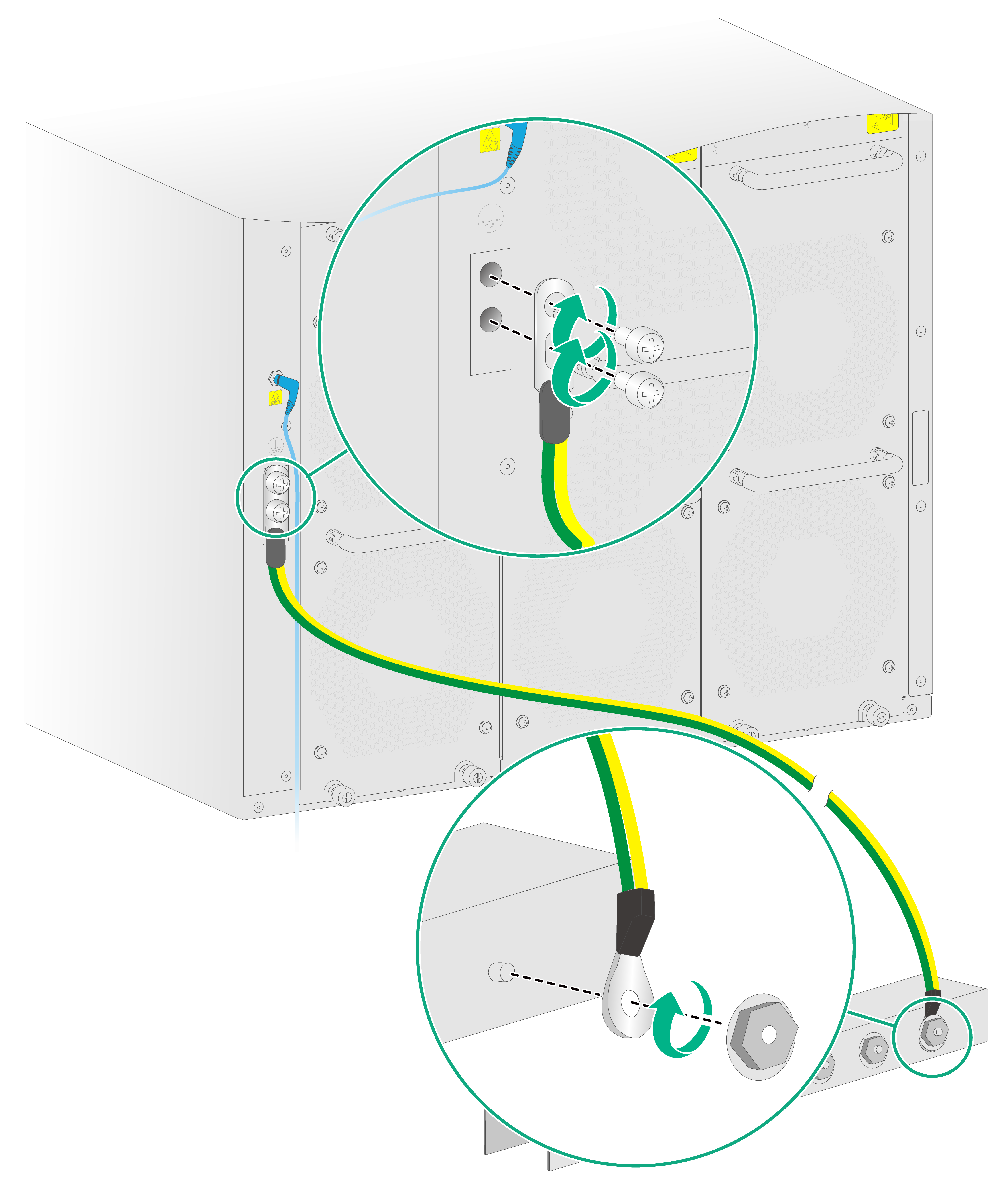
To ground the router:
1. Remove the grounding screws from the grounding point on the chassis.
2. Use the grounding screws to attach the two-hole grounding lug of the grounding cable to grounding point on the chassis.
3. Connect the ring terminal of the grounding cable to the grounding point on the rack.
Figure2-11 Grounding the router
Installing cable management brackets
|
|
IMPORTANT: To prevent cable management brackets from blocking the mounting bracket mounting holes on the rack posts, install cable management brackets after you mount the router in the rack. |
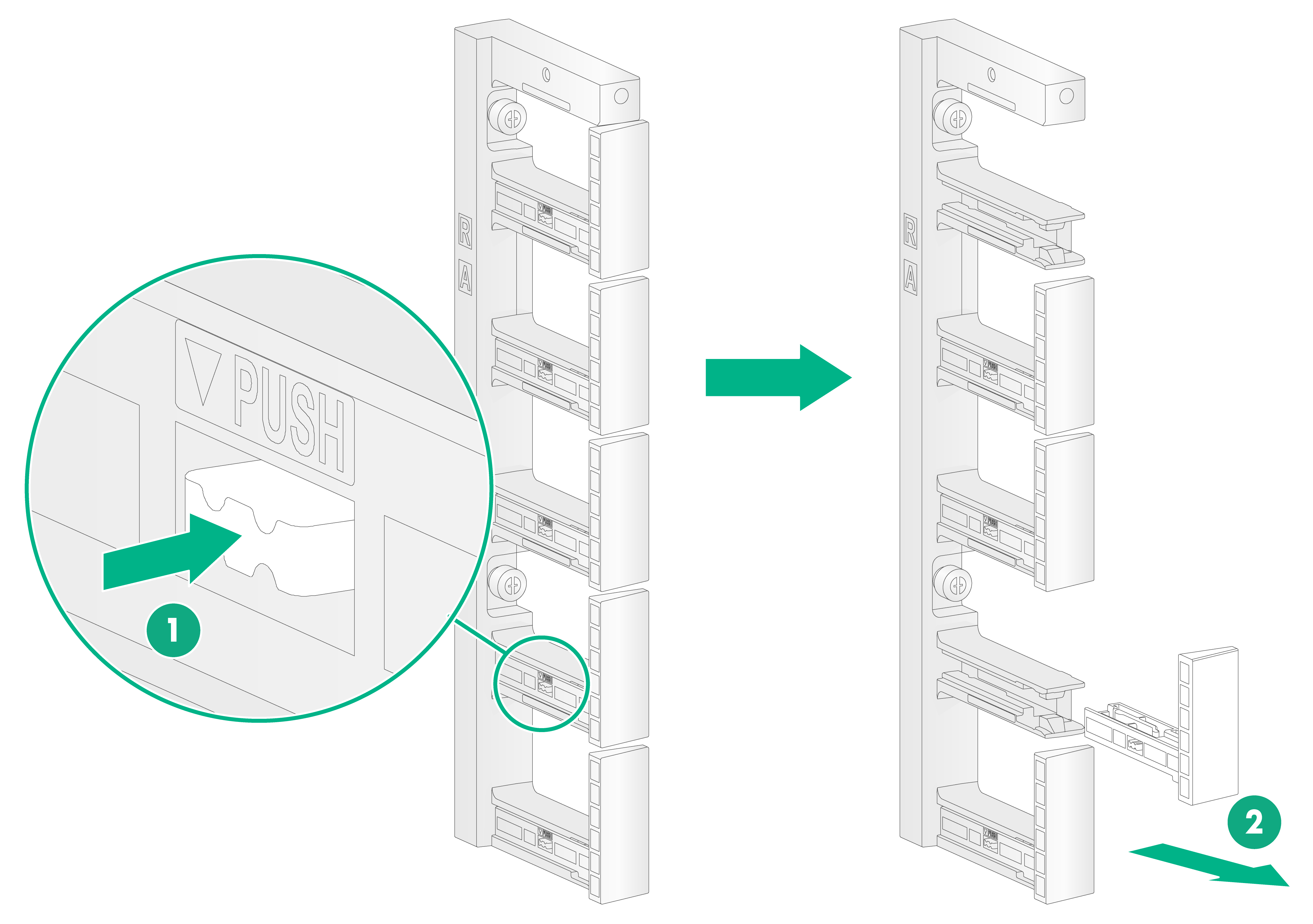
The router comes with three types of cable management brackets LA, LB/RB, and RA and two types of cable guides LA and RA. The cable management brackets come with cable guides installed.
Figure2-12 Cable management brackets

The procedure is similar for installing cable management brackets at the left side and at the right side. The following installs a cable management bracket at the right side.
To install a cable management bracket:
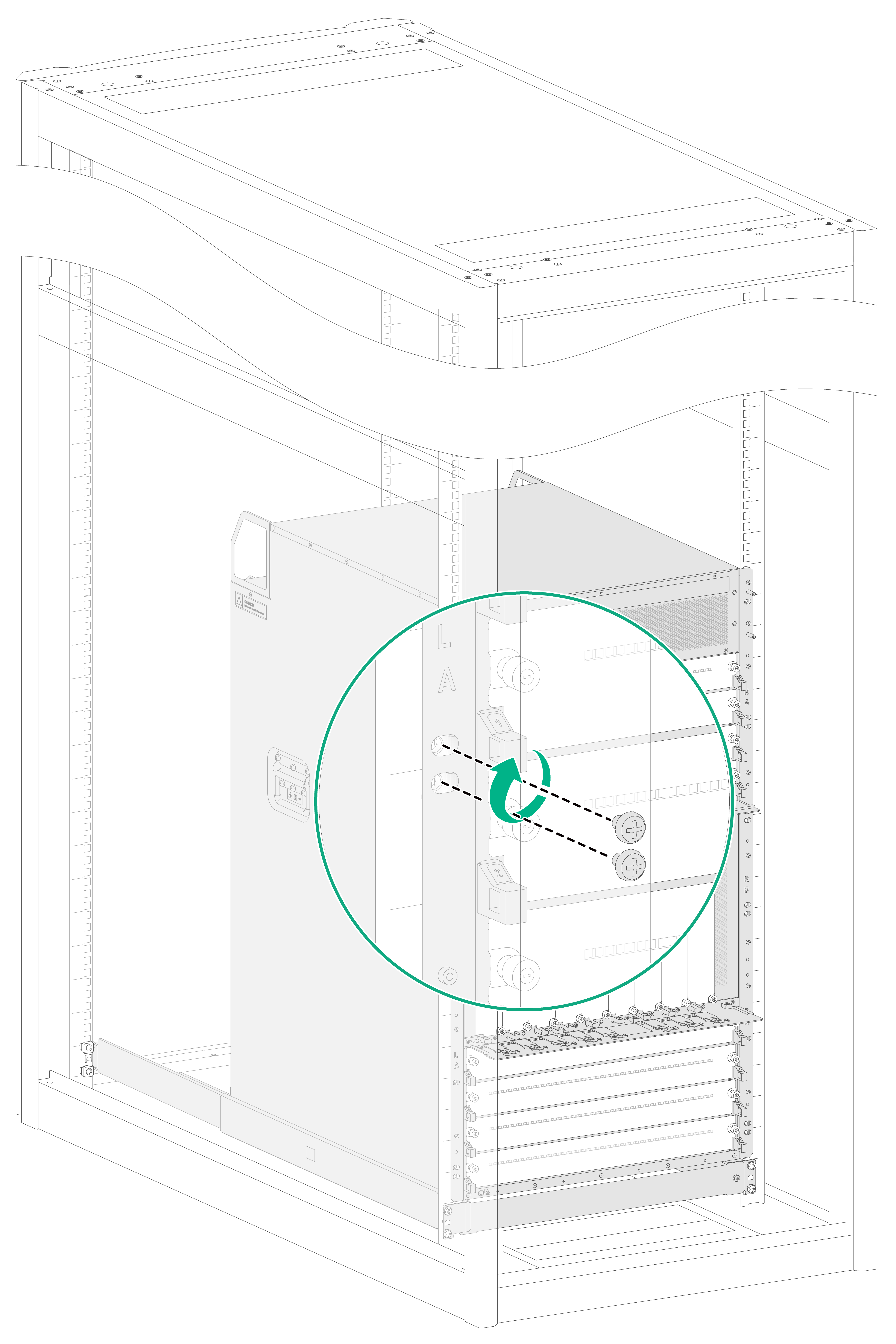
1. If any cable guide hinders installation of the cable management bracket, press the tab on the cable guide and then remove the cable guide from the cable management bracket.
Figure2-13 Removing a cable guide
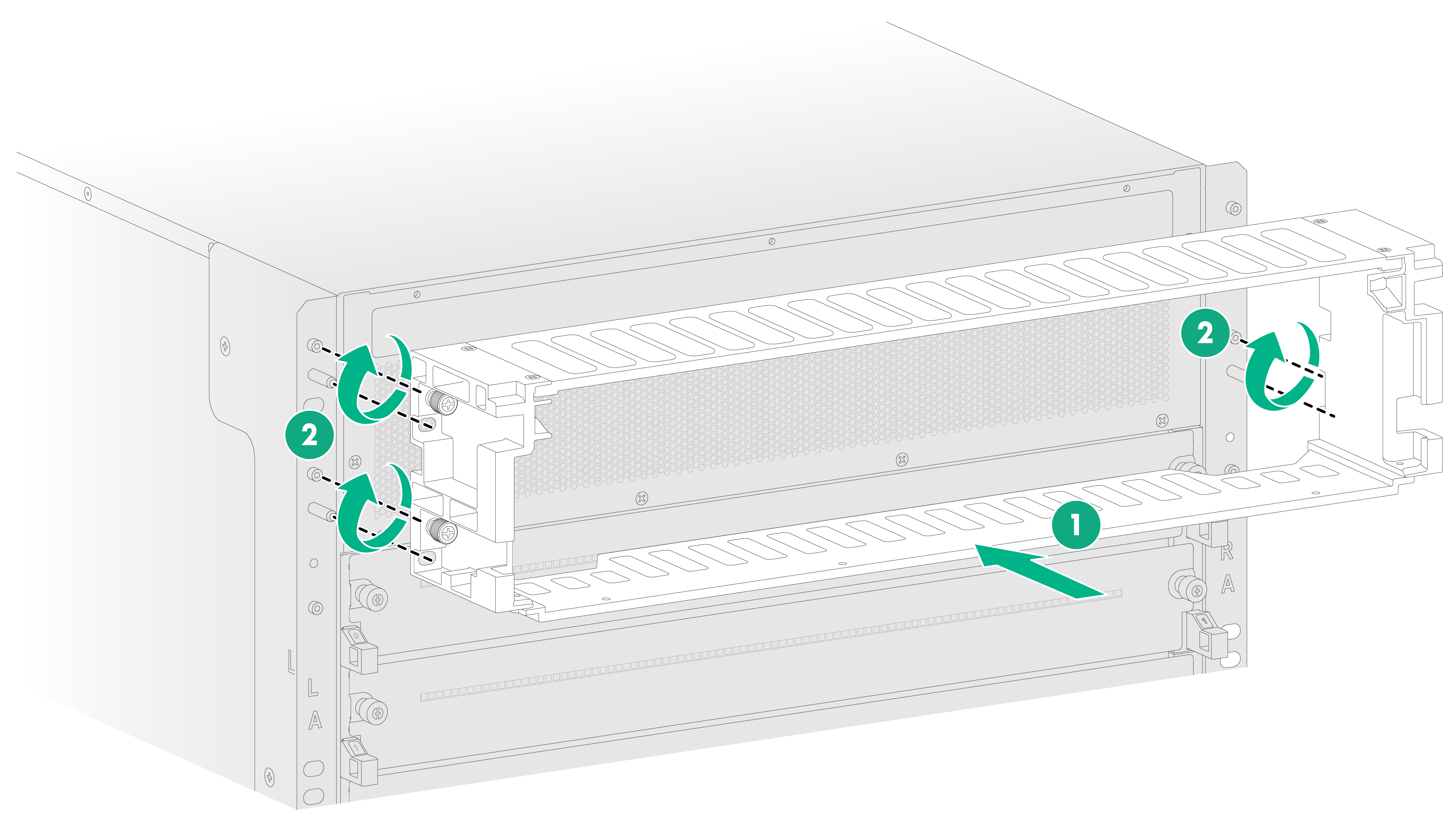
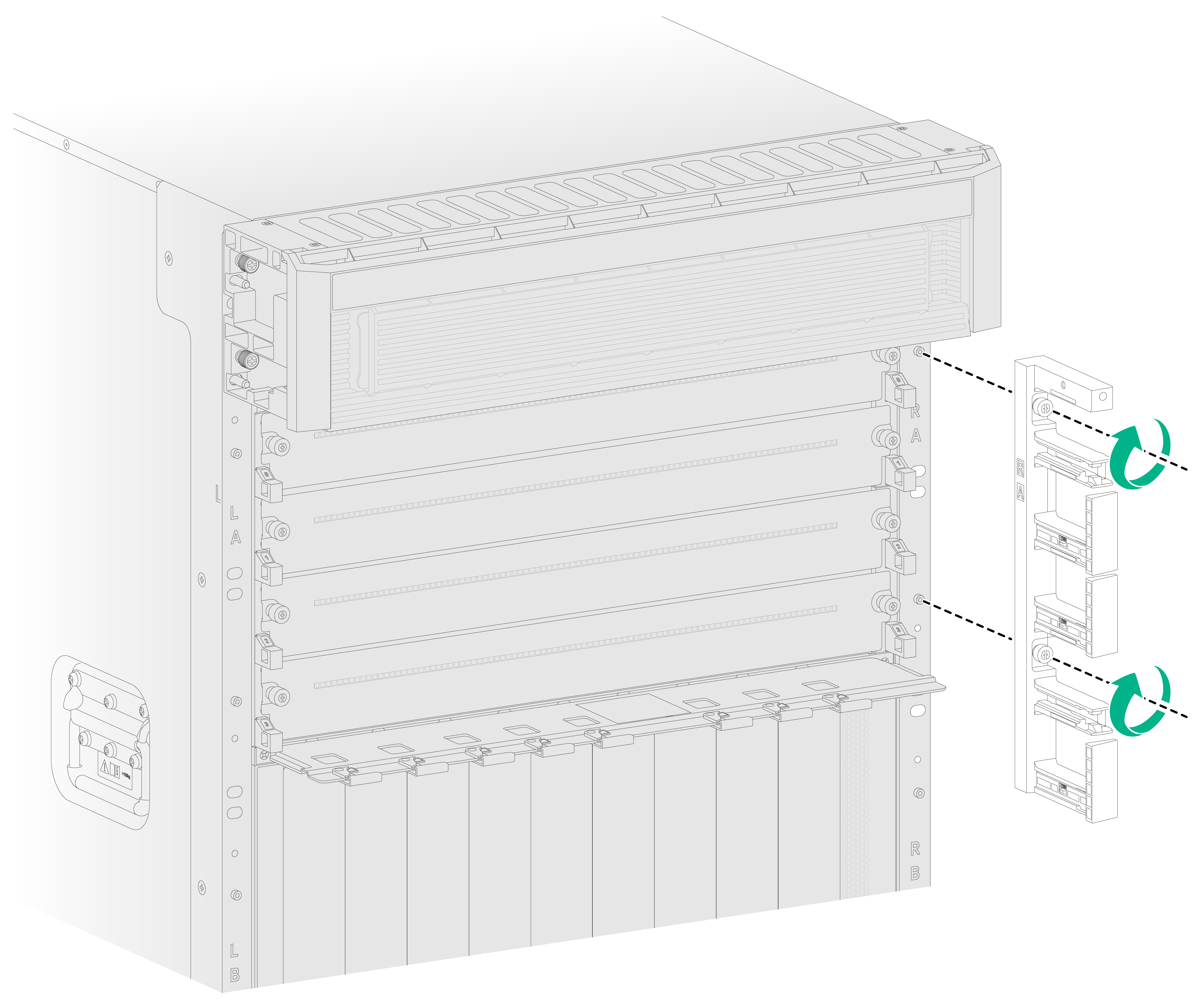
2. Identify the installation position on the mounting bracket. The LA, LB/RB, and RA marks on the mounting brackets indicate the types of cable management brackets to be installed.
3. Orient the cable management bracket, with the lettering facing upward, and then position the cable management bracket on the mounting bracket.
4. Align the captive screws on the cable management bracket with the holes in the mounting bracket. Fasten the captive screws to secure the cable management bracket.
Figure2-14 Installing a cable management bracket
5. Install the removed cable guides (if any) to the cable management bracket.
