- Table of Contents
-
- H3C CR19000-8 Core Router Installation Guide-6W103
- 00-Preface
- 01-Chapter 1 Preparing for Installation
- 02-Chapter 2 Installing the Router
- 03-Chapter 3 Installing Power Supplies
- 04-Chapter 4 Installing Removable Components
- 05-Chapter 5 Connecting Cables
- 06-Chapter 6 Verifying the Installation
- 07-Chapter 7 Accessing the Router
- 08-Chapter 8 Replacement Procedures
- 09-Chapter 9 Troubleshooting
- 10-Appendix A Engineering Labels
- 11-Appendix B Cable Management
- 12-Appendix C Repackaging the Router
- Related Documents
-
| Title | Size | Download |
|---|---|---|
| 04-Chapter 4 Installing Removable Components | 5.24 MB |
4 Installing removable components
Installing an interface module that uses detachable ejector levers
Installing an interface module that uses general ejector levers
4 Installing removable components
|
CAUTION: · Do not remove the filler panel in the slot to the right of slot 15. · If you are not to install a module or interface subcard in the slot, keep the filler panel in the slot. Keep the removed filler panels secure for future use. · Filler panels differ depending on the module type. When you install a filler panel over a slot, make sure it matches that slot. |
Slot arrangement
"LPU" in Figure4-1 refers to an interface module, "SFU" refers to a single-chassis fabric module, and "MSFU" refers to a multi-chassis fabric module.
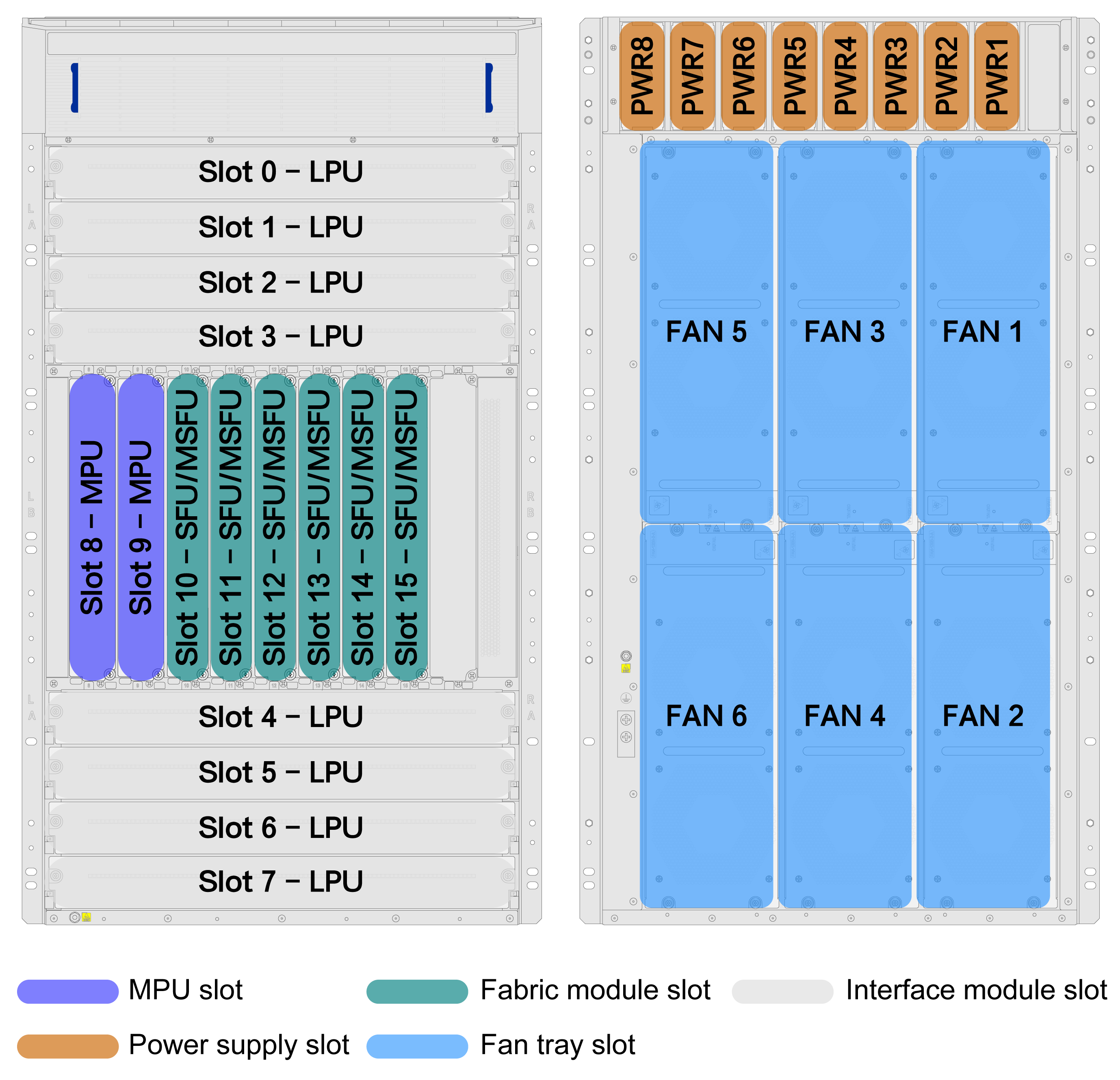
The router provides two MPU slots, six fabric module slots, eight interface module slots, eight power supply slots, and six fan tray slots.
· Slots 8 and 9 are MPU slots. Each slot supports one MPU and allows hot swapping of the MPU. The router supports 1+1 MPU redundancy and does not allow mixture of different models of MPUs.
· Slots 10 to 15 are fabric module slots. Each slot supports one fabric module and allows hot swapping of the fabric module. The router does not allow mixture of different models of fabric modules.
· Slots 0 to 3 and slots 4 to 7 are interface module slots. Each slot supports one interface module and allows hot swapping of the interface module. The router allows mixture of different models of interface modules.
Installing MPUs
|
|
CAUTION: · The router supports active/standby MPU switchover when you install two MPUs for the router. For the standby MPU to start up correctly, make sure the active and standby MPUs are the same model. · The router does not allow mixture of different models of MPUs. |
The router has two MPU slots. You can install one MPU, or two MPUs in 1+1 redundancy for the router.
To install an MPU:
1. Wear an ESD wrist strap and make sure it makes good skin contact and is reliably grounded.
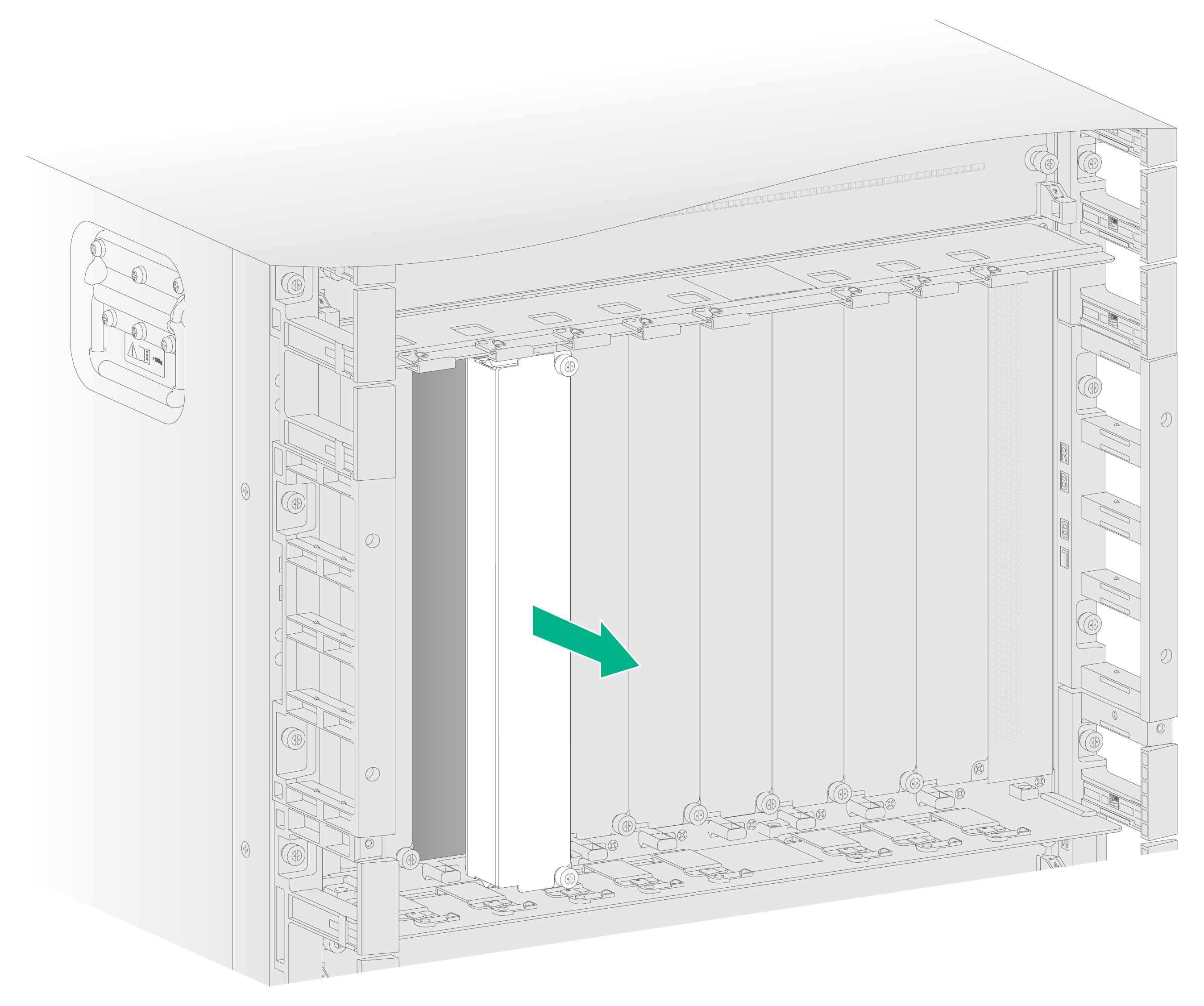
2. Remove the filler panel from the target MPU slot.
Keep the removed filler panel secure for future use.
Figure4-2 Removing a filler panel
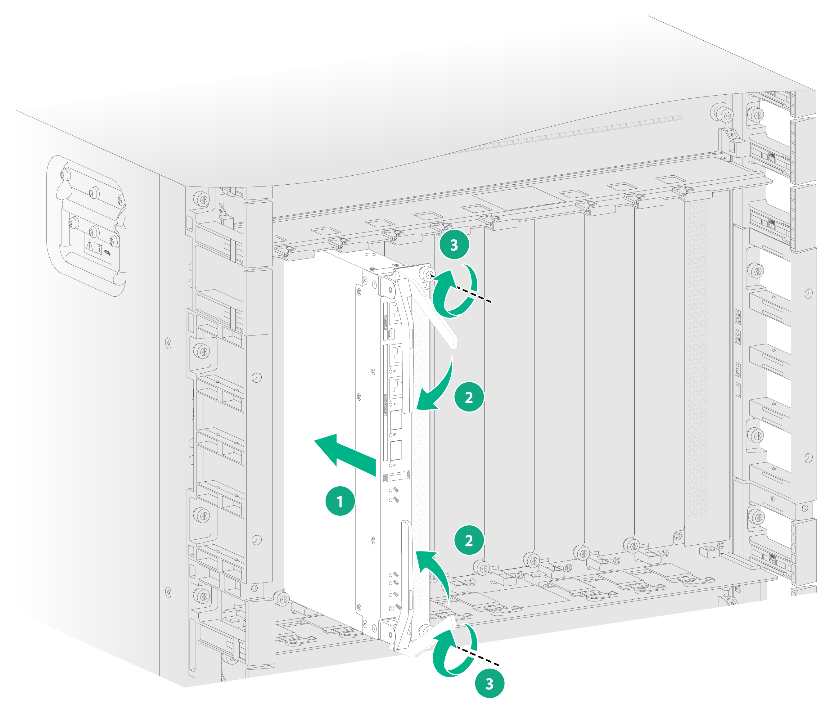
3. Orient the MPU correctly and align the MPU with the slot. Insert the MPU into the slot and fully open the ejector levers on the MPU.
4. Continue to push the MPU by its middle part on the front panel until the ejector levers touch the slot edges tightly.
5. Close the ejector levers until they come in close contact with the front panel.
6. Use a Phillips screwdriver to fasten the captive screws on the MPU.
Installing fabric modules
|
|
CAUTION: · When you install a fabric module, avoid touching the connectors on the fabric module. · The router does not allow mixture of different models of fabric module. |
The router provides six fabric module slots and supports N+1 fabric module redundancy. You can install three to six fabric modules for the router.
To install a fabric module:
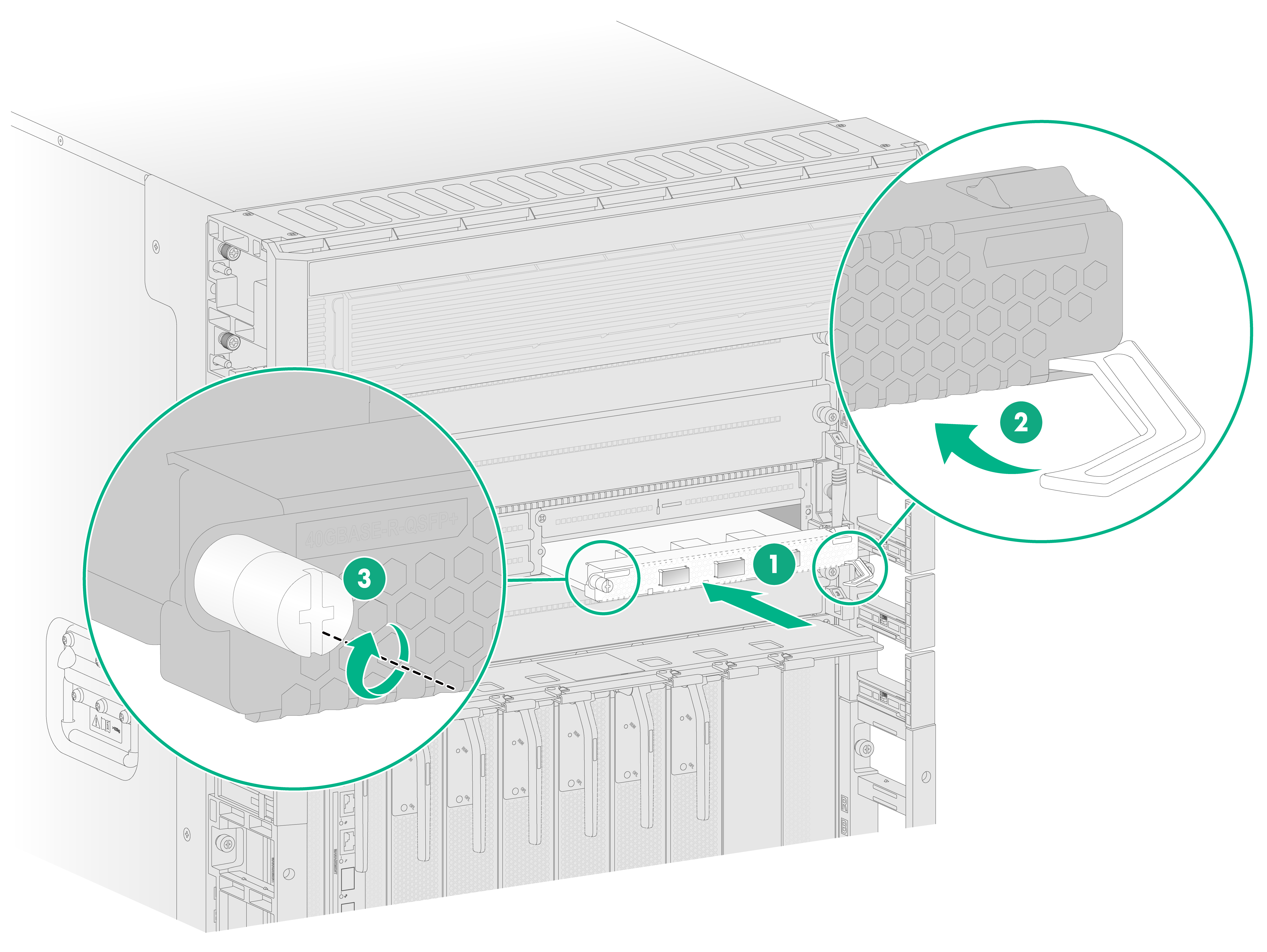
1. Place the fabric module on a workbench and remove the protection box from the connector side of the fabric module.
Figure4-4 Removing the protection box

2. Remove the filler panel from the target fabric module slot.
Keep the removed filler panel secure for future use. The method is the same for removing a filler panel from a fabric module slot and an MPU slot. For more information, see "Installing MPUs."
3. Install a fabric module. The method is the same for installing a fabric module and an MPU. For more information, see "Installing MPUs."
Installing interface modules
|
|
CAUTION: The router does not allow mixture of different models of interface modules. |
Installing an interface module that uses detachable ejector levers
|
|
CAUTION: · Put the detachable ejector lever back on its holder after use and then attach it to the chassis or cabinet for future use. · The ejector lever holder is magnetic. Be aware of electromagnetic interference. · Do not use only one detachable ejector lever to install or remove an interface module. · Do not hold detachable ejector levers to lift an interface module. |
Figure4-5 Detachable ejector lever

To install an interface module that uses detachable ejector levers:
1. Wear an ESD wrist strap. Make sure the wrist strap makes good skin contact and is reliably grounded.
2. Remove the filler panel from the target interface module slot.
Keep the removed filler panel secure for future use.
3. Remove the protection box (if any) from the connector side of the interface module, as shown in Figure4-6.
Keep the removed protection box secure for future use.
The number of screws for securing the protection box in Figure4-6 is for illustration only and the actual number of screws on your interface module might differ from that.
Figure4-6 Removing the protection box

4. Correctly orient the interface module. Align the module with the slot and push it steadily into the slot along the guide rails until about half of the module is in the slot.
Figure4-7 Installing an interface module that uses detachable ejector levers

5. Attach the ejector lever holders to the chassis or cabinet and then remove the ejector levers from the holders.
6. Identify the L and R marks on the ejector levers and attach them to left and right ejector lever retainers of the interface module, with the lettering on the ejector levers facing upward.
Figure4-8 Installing an ejector lever

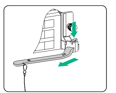
7. Open the ejector levers and continue to push the module by its middle part on the front panel until you cannot push it any further.
8. As shown in Figure4-9, close the ejector levers until they come in close contact with the front panel. Use a Phillips screwdriver to fasten the captive screws on the interface module.
Figure4-9 Closing an ejector lever
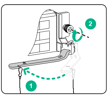
9. As shown in Figure4-10, press the spring tab on each ejector lever retainer to remove the ejector levers. Place the ejector lever back on their holders and keep them secure for future use.
Figure4-10 Removing an ejector lever
Installing an interface module that uses general ejector levers
1. Wear an ESD wrist strap. Make sure the wrist strap makes good skin contact and is reliably grounded.
2. Remove the filler panel from the target interface module slot.
Keep the removed filler panel secure for future use.
3. Open the ejector levers of the interface module.
4. Gently push the interface module into the slot along the guide rails.
5. Continue to push the interface module by its middle part on the front panel until you cannot push it any further. Then close the ejector levers.
6. Use a Phillips screwdriver to fasten the captive screws on the interface module.
7. Pivot up the ejector levers on the interface module.
Figure4-11 Installing an interface module that uses general ejector levers

Installing interface subcards
For the interface subcard compatibility with interface modules, see H3C CR19000-8 Core Router Hardware Information and Specifications.
To install an interface subcard:
1. Wear an ESD wrist strap. Make sure the wrist strap makes good skin contact and is reliably grounded.
2. Remove the filler panel from the target slot on the interface module.
Keep the removed filler panel secure for future use.
3. Open the right ejector lever of the interface subcard.
4. Insert the interface subcard into the slot and push it steadily into the slot along slide rails.
5. Continue to push the interface subcard by its middle part on the front panel until you cannot push it any further.
6. Close the right ejector lever until it comes in close contact with the front panel.
7. Use a screwdriver to fasten the captive screw on the interface subcard.
Figure4-12 Installing an interface subcard