- Table of Contents
-
- H3C CR19000-8 Core Router Installation Guide-6W103
- 00-Preface
- 01-Chapter 1 Preparing for Installation
- 02-Chapter 2 Installing the Router
- 03-Chapter 3 Installing Power Supplies
- 04-Chapter 4 Installing Removable Components
- 05-Chapter 5 Connecting Cables
- 06-Chapter 6 Verifying the Installation
- 07-Chapter 7 Accessing the Router
- 08-Chapter 8 Replacement Procedures
- 09-Chapter 9 Troubleshooting
- 10-Appendix A Engineering Labels
- 11-Appendix B Cable Management
- 12-Appendix C Repackaging the Router
- Related Documents
-
| Title | Size | Download |
|---|---|---|
| 06-Chapter 6 Verifying the Installation | 52.06 KB |
6 Verifying the installation
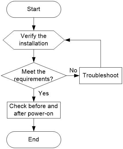
Installation verification flowchart
Figure6-1 Installation verification flowchart
Post-installation checklist
Table6-1 Post-installation checklist
|
Item |
Requirements |
|
Installation location |
· No condensation is on the surface of the router or inside the router. · The router is clean and dust-free. · No packaging boxes, packaging bags, or other packaging materials are left around the chassis. · The air inlet and outlet vents of the router are not blocked, free of obstructions. |
|
Router |
· All components are installed correctly. · Each slot is installed with a module or filler panel. · Fan trays are installed correctly. |
|
Cables |
· The router is grounded reliably with the provided grounding cable. Both ends of the grounding cable are securely connected. · No switch or fuse is installed on the grounding cable. · The power cords are connected reliably and no short circuit has occurred in power input and output. · Power cords, grounding cables, and fiber cables are routed and bound separately. · The cables are bound neatly with cable ties at an even distance. · The cable labels are correct, clear, and affixed to the cable in the same direction. |
|
Electricity safety |
· A circuit breaker is provided for each power cord. · Turn off the circuit breaker before you connect the power cord. |
Power-on check
|
|
WARNING! Locate the power switch in the equipment room before powering on the router so you can quickly shut power off when an electrical accident occurs. |
|
|
CAUTION: Before powering on the router, make sure all fan tray slots are installed with a fan tray correctly. |
Power-on check flowchart
Figure6-2 Power-on check flowchart

Checking the LEDs
After the router powers up, you can determine whether the router and the components are operating correctly by observing the LEDs on the MPUs and other components. When the router and components are operating correctly, the LEDs are as described in Table6-2 and Table6-3. If the LED states are not as described in Table6-2 and Table6-3, the router and components might be faulty. To identify and resolve the issue, see "Troubleshooting."
|
LED |
Status |
Description |
|
FAN |
Steady green |
All the fan trays are operating correctly. |
|
PWR |
Steady green |
All the installed power supplies are operating correctly. |
|
RUN |
Fast flashing green (0.5 Hz) |
The modules are operating correctly. |
|
Slow flashing green (4 Hz) |
The modules are loading software. |
|
|
ALM |
Off |
No alarm has occurred on the system. |
|
ACT |
Steady green |
The MPU is in active mode of the chassis or system. |
|
Flashing green (0.5 Hz) |
The router is in cluster mode, and the MPU is in standby mode. |
|
|
Off |
The router is in single chassis mode, and the MPU is in standby mode. |
|
|
IMPORTANT: The PWR LED on the MPU will be red if one of its installed power supplies is not operating correctly (the power cord is not connected or the circuit breaker for it is turned off). |
Table6-3 Component LED descriptions
|
LED |
Status |
Description |
|
|
Fabric module LED |
RUN |
Fast flashing green (4 Hz) |
The fabric module is loading software. |
|
Slow flashing green (0.5 Hz) |
The fabric module is operating correctly. |
||
|
Interface module LED |
RUN |
Fast flashing green (4 Hz) |
The module is loading software. |
|
Slow flashing green (0.5 Hz) |
The module is operating correctly. |
||
|
AC power supply |
AC OK DC OK |
Steady green |
The power supply is operating correctly. |
|
DC power supply |
IN OK OUT OK |
Steady green |
The power supply is operating correctly. |
|
Fan tray LED |
OK/FAIL |
Steady green |
The fan tray is operating correctly. |
