- Table of Contents
-
- H3C CR19000-8 Core Router Installation Guide-6W103
- 00-Preface
- 01-Chapter 1 Preparing for Installation
- 02-Chapter 2 Installing the Router
- 03-Chapter 3 Installing Power Supplies
- 04-Chapter 4 Installing Removable Components
- 05-Chapter 5 Connecting Cables
- 06-Chapter 6 Verifying the Installation
- 07-Chapter 7 Accessing the Router
- 08-Chapter 8 Replacement Procedures
- 09-Chapter 9 Troubleshooting
- 10-Appendix A Engineering Labels
- 11-Appendix B Cable Management
- 12-Appendix C Repackaging the Router
- Related Documents
-
| Title | Size | Download |
|---|---|---|
| 05-Chapter 5 Connecting Cables | 3.40 MB |
Contents
Connecting cables to Ethernet copper ports
Cables for connecting Ethernet copper ports
Making an Ethernet twisted pair cable
Connecting cables to fiber ports
About transceiver modules and optical fibers
Installing transceiver modules and optical fibers
Connecting a QSFP+ optical fiber
Cables for connecting E1 ports
5 Connecting cables
Connecting cables to Ethernet copper ports
Cables for connecting Ethernet copper ports
Typically, Ethernet copper ports use twisted pair cables for communication. 10/100 Mbps Ethernet uses category-5 twisted pair cables, while 1000 Mbps Ethernet uses category-5 enhanced or category-6 twisted pair cables. Twisted pair cables include straight-through cables and crossover cables.
· Category-5 cables provide a transmission frequency of 100 MHz for voice and data transmission; they are mainly used in 100BASE-T and 10BASE-T networks. Category-5 cables are the most commonly used Ethernet cables, which can also be used to transmit 1000 Mbps Ethernet data.
· Category-5 enhanced cables feature low attenuation and crosstalk, providing higher attenuation to crosstalk ratio (ACR), less delay error and higher performance than category-5 cables. Category-5 enhanced cables are mainly used in 1000 Mbps Ethernet networks.
· Category-6 cables provide a transmission frequency of 1 MHz to 250 MHz, and improve the performance on crosstalk and return loss. A fine better return loss performance is extremely important for new-generation full-duplex high-speed networks. Category-6 cables have sufficient power sum ACR (PS-ACR) when working at 200 MHz. They provide a bandwidth two times than that of category-5 enhanced cables, featuring a higher transmission performance. Therefore, category-6 cables are suitable for applications requiring a transmission speed of more than 1 Gbps.
The 10/100 Mbps Ethernet uses two pairs of cables, orange/white, orange, green/white and green cables, to transmit and receive data, while the 1000 Mbps Ethernet uses four pairs of cables to transmit and receive data.
Figure5-1 Ethernet cable

RJ-45 connector
An Ethernet twisted pair cable connects network devices by using the RJ-45 connectors at the two ends. Figure5-2 shows the pinouts of an RJ-45 connector.
Figure5-2 RJ-45 connector pinout diagram

Cable pinouts
EIA/TIA cabling specifications define two standards: 568A and 568B for cable pinouts.
· Standard 568A—pin 1: white/green stripe, pin 2: green solid, pin 3: white/orange stripe, pin 4: blue solid, pin 5: white/blue stripe, pin 6: orange solid, pin 7: white/brown stripe, pin 8: brown solid.
· Standard 568B—pin 1: white/orange stripe, pin 2: orange solid, pin 3: white/green stripe, pin 4: blue solid, pin 5: white/blue stripe, pin 6: green solid, pin 7: white/brown stripe, pin 8: brown solid.
For the pinouts of common twisted pair cables, see the following tables. (A and B represent the two ends of a cable.)
Table5-1 Straight-through cable pinouts
|
Pinout No. |
A |
B |
|
1 |
Orange/white |
Orange/white |
|
2 |
Orange |
Orange |
|
3 |
Green/white |
Green/white |
|
4 |
Blue |
Blue |
|
5 |
Blue/white |
Blue/white |
|
6 |
Green |
Green |
|
7 |
Brown/white |
Brown/white |
|
8 |
Brown |
Brown |
Table5-2 Crossover cable pinouts
|
Pinout No. |
A |
B |
|
1 |
Orange/white |
Green/white |
|
2 |
Orange |
Green |
|
3 |
Green/white |
Orange/white |
|
4 |
Blue |
Blue |
|
5 |
Blue/white |
Blue/white |
|
6 |
Green |
Orange |
|
7 |
Brown/white |
Brown/white |
|
8 |
Brown |
Brown |
|
|
NOTE: Strictly follow the pinouts in the above tables when identifying or making the two types of Ethernet cables to ensure communication quality. |
Making an Ethernet twisted pair cable
1. Cut the cable to a length as required with the crimping pliers.
2. Strip off an appropriate length of the cable sheath. The length is typically that of the RJ-45 connector.
3. Untwist the pairs so that they can lie flat, and arrange the colored wires based on the wiring specifications.
4. Cut the top of the wires even with one another. Insert the wires into the RJ-45 end and make sure the wires extend to the front of the RJ-45 end and make good contact with the metal contacts in the RJ-45 end and in the correct order.
5. Crimp the RJ-45 connector with the crimping pliers until you hear a click.
6. Repeat the above steps with the other end of the cable.
7. Use a cable tester to verify the connectivity of the cable.
Connecting an Ethernet cable
1. Connect one end of the Ethernet cable to an Ethernet copper port or management Ethernet port on the router and the other end to the target Ethernet copper port on the peer device. Because the 10BASE-T/100BASE-TX/1000BASE-T fixed Ethernet copper ports on the router and Ethernet copper ports on the modules supports auto-MDI/MDIX auto-sensing, you can use a straight-through cable or crossover cable to connect the ports.
2. Examine the status LED for the Ethernet port to verify the cable connectivity. For the description of the port LEDs, see H3C CR19000-8 Core Router Hardware Information and Specifications.
Connecting cables to fiber ports
About transceiver modules and optical fibers
To connect a fiber port, install an SFP, SFP+, XFP, CFP2, QSFP28, or QSFP+ transceiver module in the fiber port and connect optical fibers with LC or MPO fiber connectors to the transceiver module.
Optical fibers can be classified into the following types:
· Single mode fiber—It has a core size of 10 µm or smaller, and has a lower modal dispersion. It carries only a single ray of light. It is mostly used for communication over longer distances.
· Multi-mode fiber—It has a core size of 50 µm or 62.5 µm or higher, and has a higher modal dispersion than single-mode optical fiber. It is mostly used for communication over shorter distances.
Fiber connectors are indispensable passive components in an optical fiber communication system. They allow the removable connection between optical channels, which makes the optical system debugging and maintenance more convenient and the transit dispatching of the system more flexible. The router support LC and MPO fiber connectors.
Do not use excessive force when you install or remove a fiber connector. Avoid pulling, pressing and squeezing optical fibers with force.
Table5-3 Allowed maximum tensile force and crush load
|
Period of force |
Tensile load (N) |
Crush load (N/mm) |
|
Short period |
150 |
500 |
|
Long term |
80 |
100 |
Installing transceiver modules and optical fibers
|
|
WARNING! Disconnected optical fibers or transceiver modules might emit invisible laser light. Do not stare into beams or view directly with optical instruments when the router is operating. |
|
|
CAUTION: · Before installing a transceiver module, remove the optical fibers, if any, from it. For more information about installing transceiver modules, see the installation guide for the transceiver modules. · If you are not to use a fiber port or transceiver module, insert dust plugs into the port or module. If you are not to connect an optical fiber, install dust caps for the fiber connector. |
To install a transceiver module and optical fiber:
1. Wear an ESD wrist strap and make sure the wrist strap is reliably grounded.
2. Remove the dust plug from the target fiber port.
3. Pull the bail latch on the transceiver module upwards.
Skip this step if the bail latch is plastic.
4. Take the transceiver module by its two sides and align it with the fiber port.
5. Push the transceiver module gently into the port until it is firmly seated in the fiber port.
6. Remove the dust plug and dust cap from the transceiver module and fiber connector, respectively.
7. Connect the optical fiber to the transceiver module.
¡ LC connector—Align the connector with the transceiver module and push it into the transceiver module slightly until it clicks into place.
¡ MPO connector—Orient the connector with the white spot on it facing right. Insert the MPO fiber connector horizontally into the transceiver module. Push the MPO fiber connector into the transceiver module slightly until it clicks into place.
8. Use cable ties at a spacing of 150 mm (5.91 in) to bind optical fibers.
9. Label optical fibers according to the cable labeling specifications.
Figure5-3 Installing a transceiver module and optical fiber (LC port)

Figure5-4 Installing a transceiver module and optical fiber (MPO port)

Connecting a QSFP+ optical fiber
|
|
WARNING! Disconnected optical fibers or transceiver modules might emit invisible laser light. Do not stare into beams or view directly with optical instruments when the router is operating. |
|
|
CAUTION: For interface modules with dust plugs shipped as accessories, insert dust plugs into open fiber port timely. |
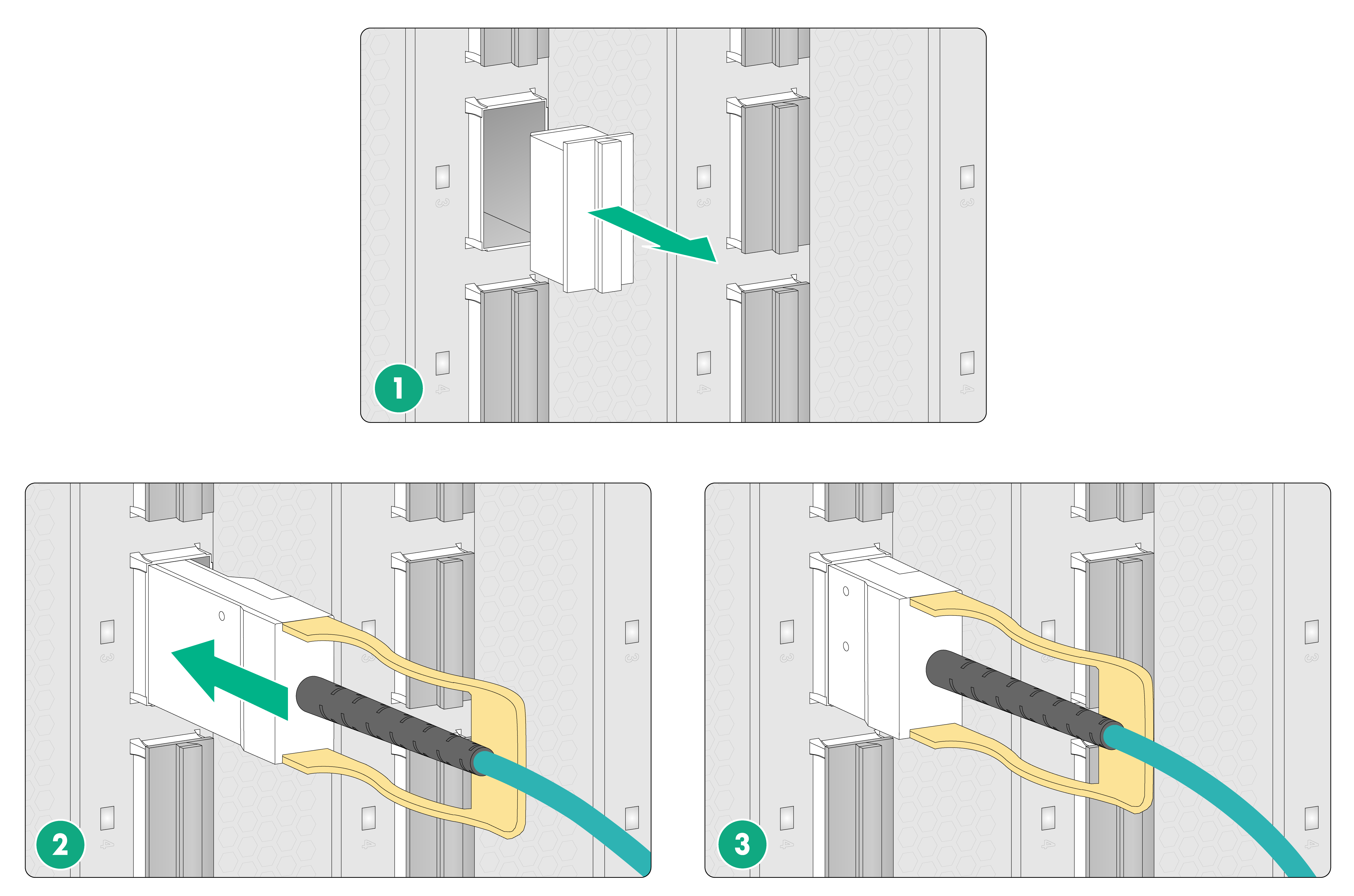
To connect a QSFP+ optical fiber:
1. Wear an ESD wrist strap and make sure the wrist strap is reliably grounded.
2. Remove the dust plug from the target fiber port.
3. Orient the cable with the pull tab on the QSFP+ module facing right. Push the module gently into the port until it is firmly seated in the fiber port.
4. Use cable ties at a spacing of 150 mm (5.91 in) to bind optical fibers.
5. Label optical fibers according to the cable labeling specifications.
Figure5-5 Connecting a QSFP+ optical fiber
Connecting cables to E1 ports
Cables for connecting E1 ports
You can use an E1 cable to connect an E1 port (HM96 male connector). Typically, an E1 cable has an HD96 female connector at one end and multiple BNC, RJ-45, or SMB connectors at the other end.
When connecting an E1 cable, you might need also coaxial connectors and 75-ohm E1 adapter cables. No coaxial connectors and 75-ohm E1 adapter cables are provided with interface subcards. Purchase them yourself as needed.
Connecting an E1 cable
|
|
CAUTION: To avoid interface subcard or chassis damage, identify the target E1 port before your connection. Avoid connecting the cable to another port. |
Connecting an E1 120-ohm RJ-45 cable
1. Connect the HD96 connector of the E1 120-ohm cable to the HM96 connector on the interface subcard and fasten the screws on the connector.
2. Connect the RJ-45 connectors at the other end of the E1 cable to the peer device.
Connecting an E1 75-ohm BNC/SMB cable
The E1 75-ohm BNC cable and SMB cable use the same connection procedure. The following procedure connects an E1 75-ohm BNC cable.
To connect an E1 75-ohm BNC cable:
· If you do not need to extend the cable, perform these steps:
a. Connect the HD96 connector of the E1 75-ohm cable to the HM96 connector on the interface subcard and fasten the screws on the connector.
b. The other end of the cable provides multiple pairs of 75-ohm BNC connectors. Identify the number of each pair of BNC connectors. Connect the TX connector and the RX connector of the cable to the RX connector and the TX connector on the peer device, respectively.
Figure5-6 Connecting an E1 75-ohm cable

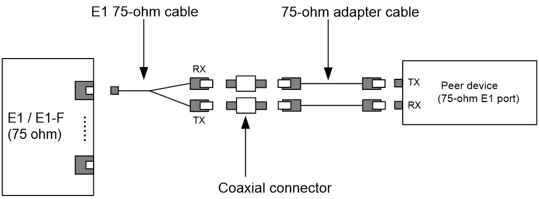
· If you need to extend the cable, connect each BNC connector of the E1 75-ohm cable to a coaxial connector and then use an E1 75-ohm adapter cable to connect the coaxial connector to the peer device.
Figure5-7 Connecting an E1 75-ohm cable (using coaxial connectors and 75-ohm adapter cables)
· If the impedance of the E1 port on the peer device is 120 ohms, you must use an impedance converter to adapt the impedance.
Figure5-8 Connecting an E1 75-ohm cable (using an impedance converter)

