- Table of Contents
-
- H3C CR19000-8 Core Router Installation Guide-6W103
- 00-Preface
- 01-Chapter 1 Preparing for Installation
- 02-Chapter 2 Installing the Router
- 03-Chapter 3 Installing Power Supplies
- 04-Chapter 4 Installing Removable Components
- 05-Chapter 5 Connecting Cables
- 06-Chapter 6 Verifying the Installation
- 07-Chapter 7 Accessing the Router
- 08-Chapter 8 Replacement Procedures
- 09-Chapter 9 Troubleshooting
- 10-Appendix A Engineering Labels
- 11-Appendix B Cable Management
- 12-Appendix C Repackaging the Router
- Related Documents
-
| Title | Size | Download |
|---|---|---|
| 01-Chapter 1 Preparing for Installation | 3.33 MB |
General safety recommendations
Examining the installation site
Unpacking and inspecting the router
Unpacking and inspecting the components
1 Preparing for installation
Safety recommendations
To avoid bodily injury and damage to the router, read all safety recommendations including the compliance and safety manual for the router carefully before installation. Note that the recommendations do not cover every possible hazardous condition.
General safety recommendations
· Keep the chassis clean and dust-free.
· Do not place the router on a moist area, and avoid liquid flowing into the router.
· Make sure the ground is dry and flat and anti-slip measures are in place.
· Ensure good ventilation in the equipment room and keep the air inlet and outlet vents of the router free of obstruction.
· When servicing the device, do not wear loose clothing or any other things that could get caught in the chassis and remove all metal jewelry such as watches, bracelets, and necklaces.
· Use a screwdriver to fasten screws.
· After completing the installation, move the empty packaging materials and installation tools away from the router.
· Keep the chassis and installation tools away from walk areas.
Electricity safety
· Clear the work area of possible electricity hazards, such as ungrounded power extension cables, missing safety grounds, and wet floors.
· Locate the emergency power-off switch in the room before installation so you can quickly shut power off when an electrical accident occurs.
· Remove all external cables, including power cords, before moving the chassis.
· Do not work alone when servicing the router with power present.
· Never assume that power has been disconnected from a circuit. Always check.
ESD prevention
|
|
CAUTION: Make sure the resistance reading between human body and the ground is in the range of 1 to 10 megohms (Mohms). |
Preventing electrostatic discharge
To prevent electrostatic discharge (ESD) damage, follow these guidelines:
· Ground the router reliably. For how to ground your router, see "Grounding the router."
· Always wear an ESD wrist strap when installing removable components. Make sure the wrist strap is reliably grounded.
· Hold a module by its edges. Do not touch any electronic components or PCB.
· Put a module in an antistatic bag and keep it secure if you are not to install it in the chassis.
Attaching an ESD wrist strap
1. Wear the wrist strap on your wrist.
2. Lock the wrist strap tight around your wrist to keep good contact with the skin.
3. Insert the ESD wrist strap into an ESD jack on the chassis.
The router has one ESD jack on both the front and rear panels.
4. Make sure the rack is reliably grounded.
Laser safety
|
|
WARNING! · Disconnected optical fibers or transceiver modules might emit invisible laser light. Do not stare into beams or view directly with optical instruments when the router is operating. · Before you remove the optical fiber connector from a fiber port, execute the shutdown command in interface view to shut down the port. |
|
|
CAUTION: · Insert dust caps into open optical fiber connectors to protect them from contamination and ESD damage. · Insert dust plugs into open fiber ports and transceiver module ports to protect them from contamination and ESD damage. |
Moving safety
|
|
WARNING! Hold the chassis handles firmly to move the router. |
|
|
CAUTION: Do not hold air vents of the chassis, the handle of a fan tray or power supply, or an ejector lever of a module to move the router. Doing so might cause equipment damage. |
The router is heavy and large. When you move the router, follow these guidelines:
· Remove all power supplies, modules, and external cables (including power cords) before moving the chassis.
· Moving the chassis requires a minimum of four people. As a best practice, use a mechanical lift to move the chassis.
· Lift and put down the chassis slowly and never move it suddenly.
· Pay attention to the safety symbols on the package and handle the router accordingly. (The symbols in Table1-1 are for illustration only. The symbols on your device packages might differ from these ones.)
|
Symbol |
Description |
|
|
Do not stack the devices beyond the specified number (n) |
|
|
Place the device with the arrows up. |
|
|
The device is fragile. Handle it with care. |
|
|
Keep the device from humidity, rains, and wet floor. |


Examining the installation site
The router must be used indoors. To ensure correct operation and long service life of your router, make sure the installation site meets the following requirements.
Weight support
Make sure the floor or ground at the installation site can support the combined weight of the router and the rack. The total weight of the router includes the chassis and its components (for example, modules, fan trays, power supplies, and cables) and accessories. For the weights of the router and its components, see "Weights and dimensions."
To mount the switch in a rack, select slide rails that can support the total weight of the router.
To assess the load-bearing requirements for the floor and slide rails, take potential system expansion (for example, adding more modules) also in consideration.
Space
|
|
IMPORTANT: · The rack must have a front door (single door as a best practice) and a rear door. · For easy installation and maintenance, reserve a minimum clearance of 1200 mm (47.24 in) between the rack and walls or other devices. |
Table1-2 Router dimensions and rack requirements
|
Model |
Chassis dimensions |
Rack requirements |
|
CR19000-8 |
· Height—843 mm (33.19 in)/19 RU · Width—440 mm (17.32 in) · Depth—745 mm (29.33 in) ¡ 650 mm (25.59 in) for the chassis ¡ 95 mm (3.74 in) from the rack-mounting surface of the mounting bracket to the cable management bracket front end |
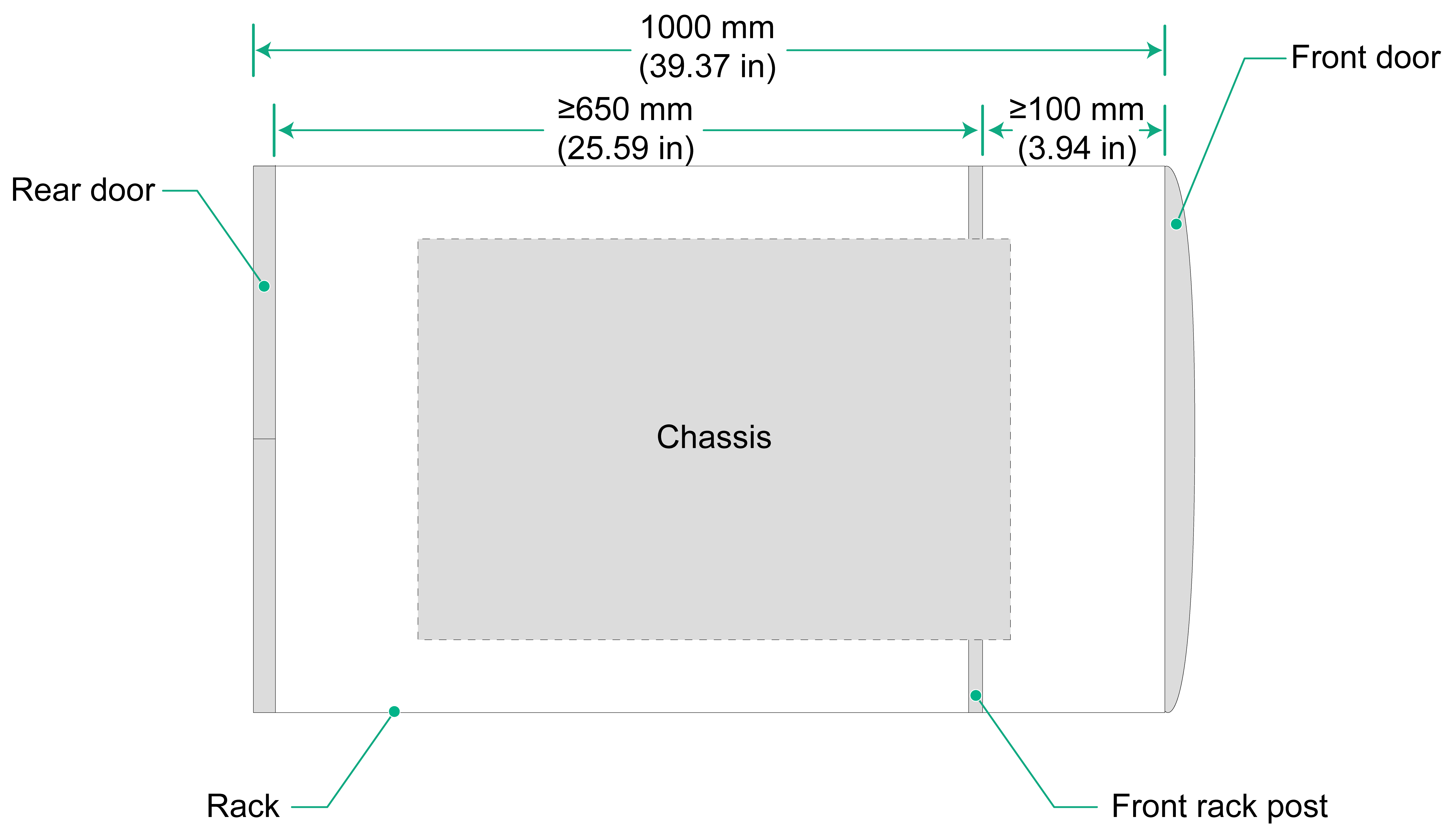
· A minimum of 1000 m (39.37 in) in depth (recommended). · You can also use a rack with a depth of 800 mm (31.50 in) (with the door thickness not exceeding 25 mm (0.98 in). · A minimum of 100 mm (3.94 in) between the front rack posts and the front door. · A minimum of 650 mm (25.59 in) between the front rack posts and the rear door. |
Figure1-1 Chassis dimensions
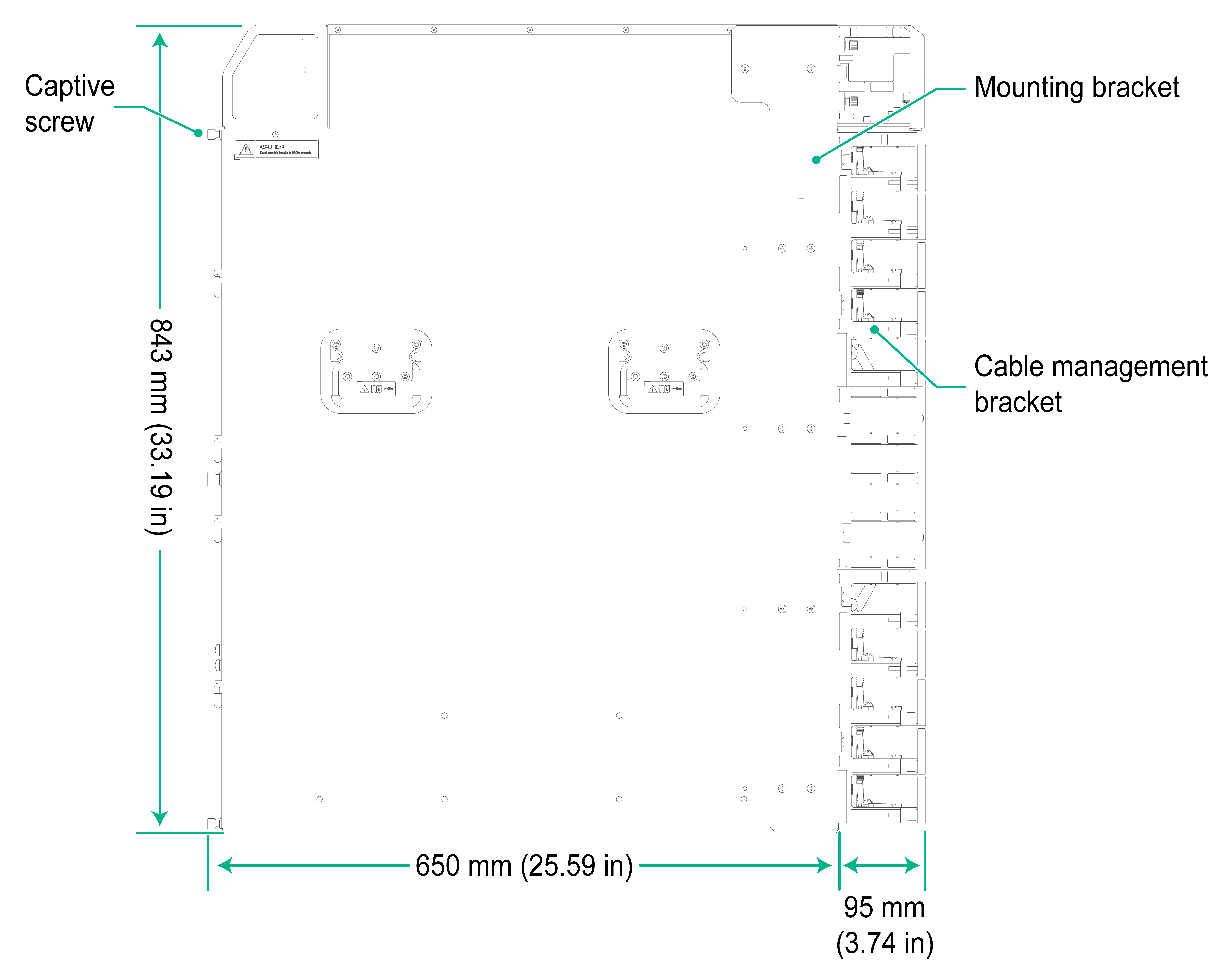
Figure1-2 Rack requirements
Cooling
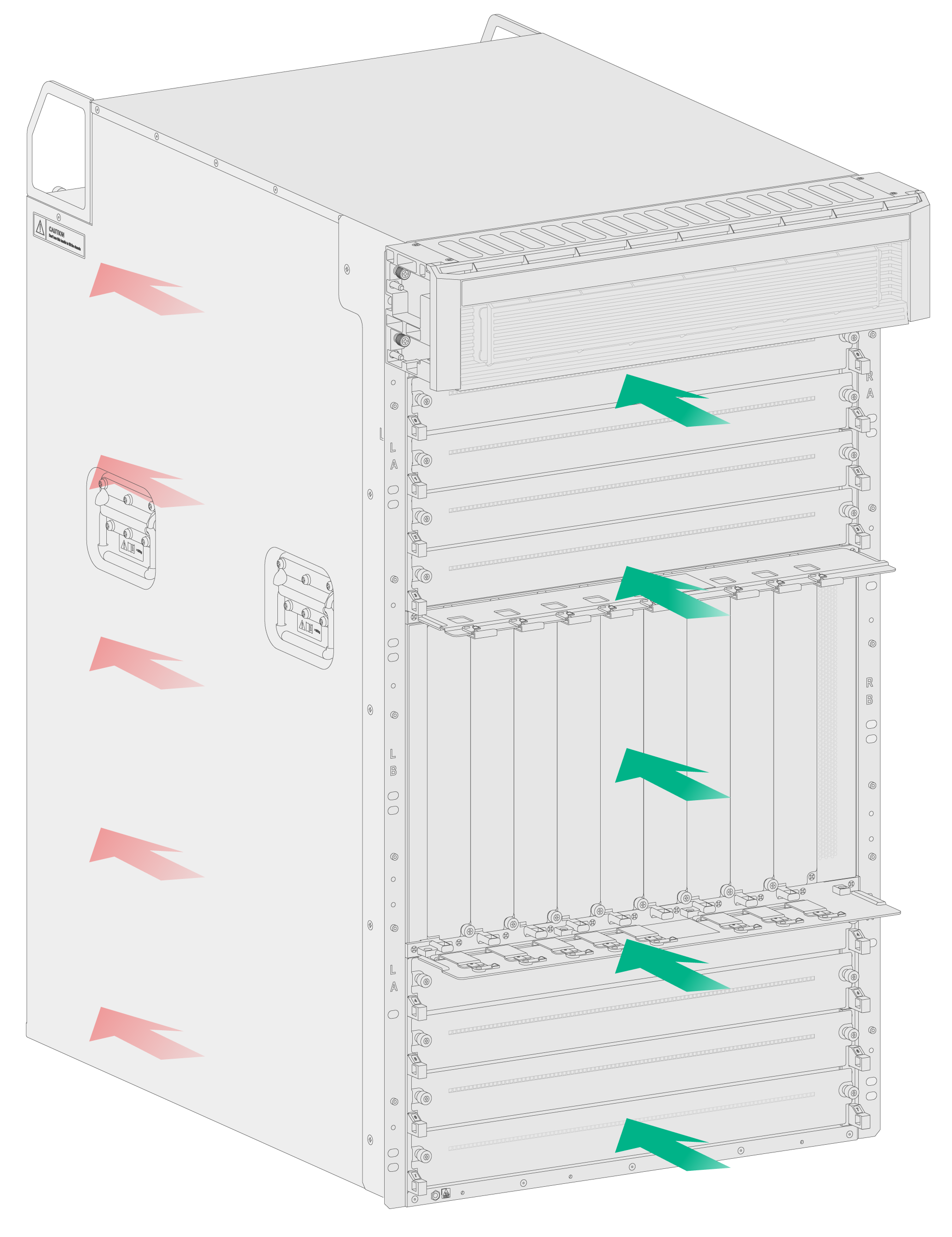
The router uses super-short cut-through ventilation aisles to provide front-to-rear airflow for heat dissipation, as shown in Figure1-3.
For adequate cooling of the device, make sure the following requirements are met:
· Plan the installation location for the router based on its airflow direction.
· The air inlet and outlet vents of the router are not blocked and adequate clearance is reserved around the air vents.
· The rack for the router has a good cooling system, with the perforation rate of rack doors greater than 50%.
· The installation site has a good cooling system.
· The air conditioners do not blow air directly onto the router.
Figure1-3 Airflow through the chassis
Power supply
Power supply system
A good power supply system is essential for correct operation of the router. The router supports AC and DC power inputs. Make sure the equipment room meets the following requirements for the power supply systems.
· The AC power supply system is stable and reliable and capable of providing power required by the router. A diesel generator is available in the equipment room as a backup power source.
· The DC power supply system is stable and reliable and its output voltage is stable and within the acceptable range allowed by the device.
· Enough batteries are available to ensure uninterrupted device operation in the event of a power failure.
Power
For the power supply system to provide power as required by the router:
· Determine the number of power supplies based on the total power consumption of the router. Make sure the total maximum output power of the power supplies is greater than the total power consumption of the router.
· Verify that the power supply system at the installation site is stable and provides power that meets the power supply specifications, including the rated input voltage and input current.
For the power supply specifications, see "Power supplies."
Grounding
Correctly grounding the router is crucial to lightning protection, anti-interference, and ESD prevention. Use a good grounding system for the router. Make sure the resistance between the chassis and the ground is less than 1 ohm.
For more information about grounding the router, see "Grounding the router."
Temperature and humidity
|
CAUTION: If condensation occurs on the chassis when you move it from a lower temperature to a higher temperature, dry the chassis before powering it on to avoid short circuits. |
If the temperature in the equipment room is too high, too low, or changes dramatically, the device reliability is reduced and its service lifetime is shortened. For long-term, highly available operation of the router, make sure temperature and humidity in the equipment room meets the requirements described in Table1-3.
· High temperature can accelerate the aging of insulation materials and significantly lower the reliability and lifespan of the router.
· Lasting high relative humidity can cause poor insulation, electricity leakage, mechanical property change of materials, and metal corrosion.
· Lasting low relative humidity can cause washer contraction and ESD and bring problems including loose screws and circuit failure.
Table1-3 Temperature and humidity requirements
|
Item |
Operating |
Storage |
|
Temperature |
0°C to 45°C (32°F to 113°F) |
–40°C to +70°C (–40°F to +158°F) |
|
Humidity |
5% RH to 95% RH, noncondensing |
5% RH to 95% RH, noncondensing |
Cleanliness
Mechanically active substances buildup on the chassis might result in electrostatic adsorption, which causes poor contact of metal components and contact points. In the worst case, electrostatic adsorption can cause communication failure.
Table1-4 Mechanically active substance concentration limit in the equipment room
|
Substance |
Particle diameter |
Concentration limit |
|
Dust particles |
≥ 5 µm |
≤ 3 × 10⁴ particles/m3 (No visible dust on desk in three days) |
|
Dust (suspension) |
≤ 75 µm |
≤ 0.2 mg/m3 |
|
Dust (sedimentation) |
75 µm to 150 µm |
≤ 1.5 mg/(m2h) |
|
Sand |
150 µm to 1000 µm |
≤ 30 mg/m3 |
To maintain cleanliness in the equipment room, follow these guidelines:
· Use dustproof materials for floors and walls and use coating that does not produce powders.
· Use double-layer glass in windows and seal doors and windows with dust-proof rubber strips. Use screen doors and screen windows in the external side.
· Keep the equipment room clean and clean the air filters of the rack regularly.
· Wear ESD clothing and shoe covers before entering the equipment room.
Harmful gas limit
The equipment room must also meet limits on salts, acids, and sulfides to eliminate corrosion and premature aging of components, as shown in Table1-5.
Table1-5 Harmful gas limits in the equipment room
|
Gas |
Maximum concentration (mg/m3) |
|
SO2 |
0.2 |
|
H2S |
0.006 |
|
NH3 |
0.05 |
|
Cl2 |
0.01 |
|
NO2 |
0.04 |
To control harmful gases, use the following guidelines:
· Use environmentally friendly materials to decorate the equipment room. Avoid using materials that contains harmful gases, such as sulfur or chlorine-containing insulation cottons and rubber mats.
· Keep the air inlet of the equipment room away from the pollution source and the sewer.
· Place batteries separately, preferably in a separate room.
· Employ a professional company to monitor and control harmful gases in the equipment room regularly.
EMI
All electromagnetic interference (EMI) sources, from outside or inside of the router and application system, adversely affect the router in the following ways:
· A conduction pattern of capacitance coupling.
· Inductance coupling.
· Electromagnetic wave radiation.
· Common impedance (including the grounding system) coupling.
To prevent EMI, use the following guidelines:
· Take effective measures to filter interference from the power grid.
· Separate the working earthing system of the router from the grounding facility and lightning protection facility of the other electrical devices as far as possible.
· Keep the router far away from radio transmitting stations, radar stations, and high-frequency devices.
· Use electromagnetic shielding, for example, shielded interface cables, when necessary.
Unpacking and inspecting the router
Physical specifications
Table1-6 Physical specifications
|
Model |
Shipping weight |
Dimensions (H × W × D) |
|
CR19000-8 |
115 kg (253.53 lb) |
843 × 440 × 650 mm (33.19 × 17.32 × 25.59 in) |
|
|
NOTE: The shipping weight of the router includes the chassis and packaging material. You can determine a moving method for the chassis based on its shipping weight. |
Unpacking the chassis
|
|
WARNING! To avoid bodily injury, wear protective gloves when unpacking the chassis. |
|
|
CAUTION: · To avoid device damage, move the carton to a location close to the installation site before unpacking it. · Do not place the carton upside down. · If you find the router water-soaked or its surface rusted, stop unpacking it and contact the equipment supplier. · Use a mechanical lift to move the shipping pallet and keep the router upright during the moving process. · If no mechanical lift is used, cooperate with a minimum of four people to move the chassis by using the chassis handles. · When transporting, moving, and installing the chassis, be careful not to bump the router into the door or wall. |
To unpack the chassis:
1. Place the carton flat on the floor with the pallet at the bottom.
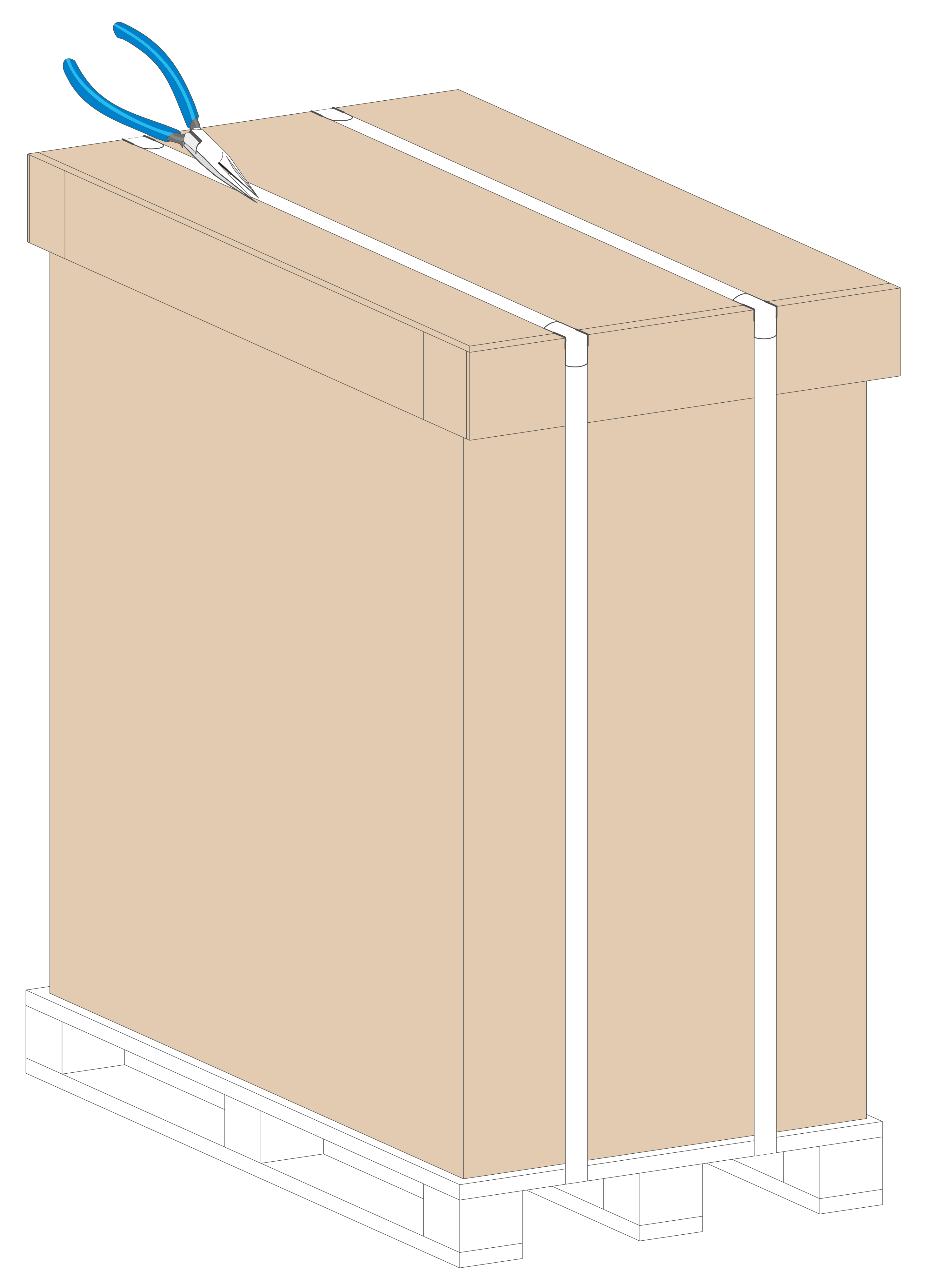
2. Use scissors or diagonal pliers to cut the straps on the carton.
Figure1-4 Cutting the strap on the carton
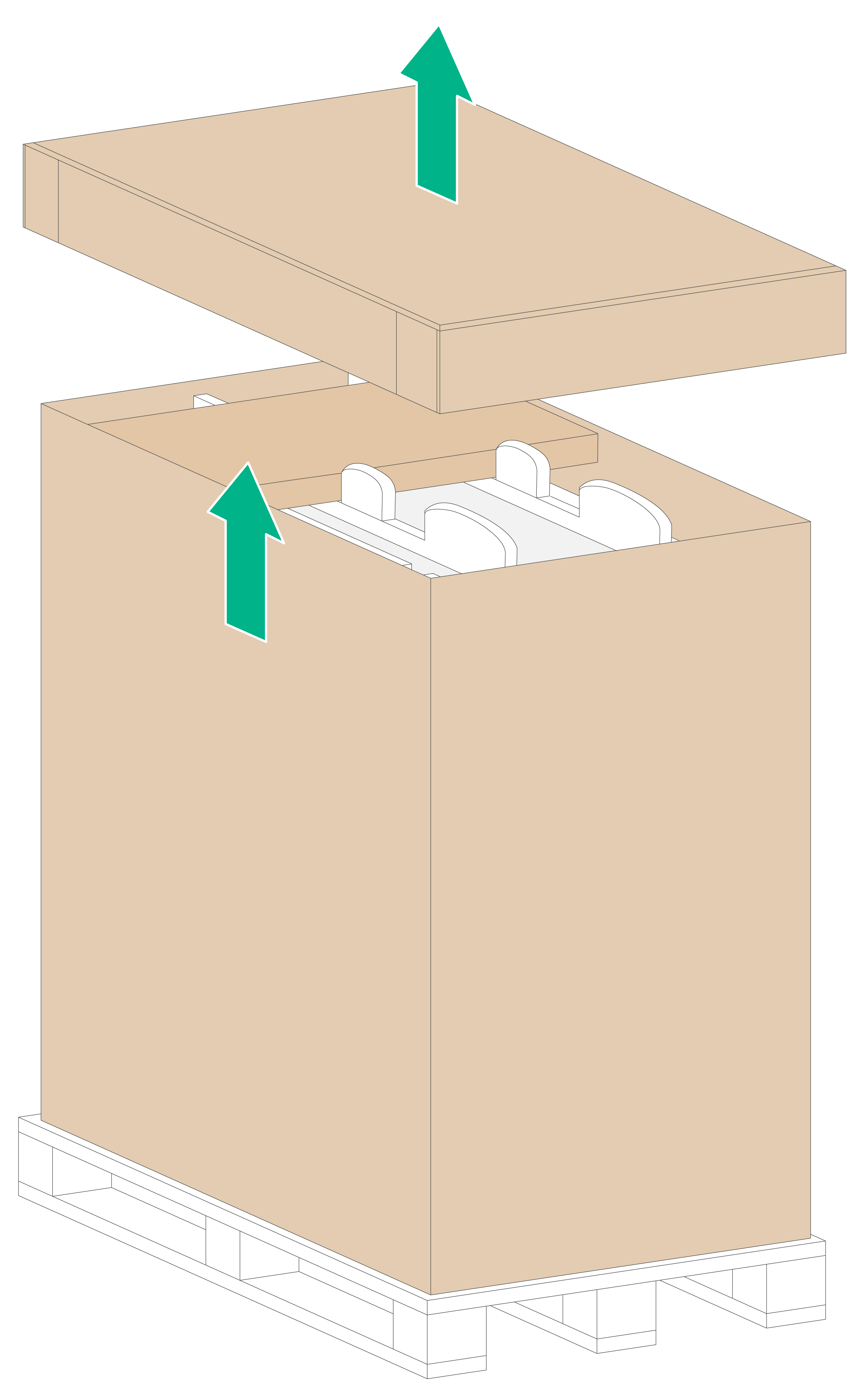
3. Lift the top cap from the carton, take out the accessory box, and remove the packaging materials such as the packaging carton and foam cushion.
Verify that the accessory box package is intact. Check the accessories against the packing list.
Figure1-5 Removing the top cap from the carton
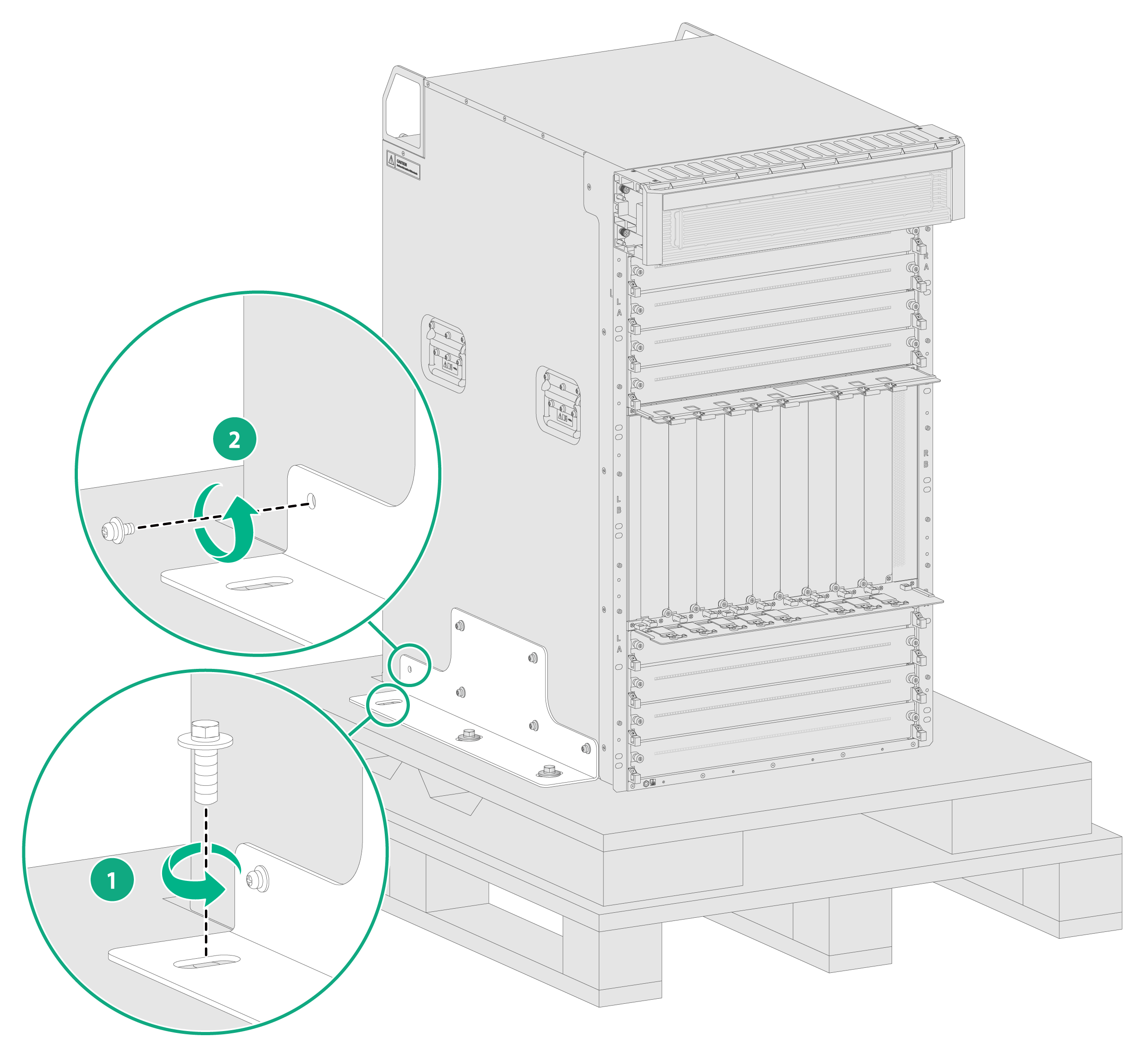
4. Use Philips screwdrivers and adjustable wrench to remove the screws on the L-type brackets, to separate the router from the pallet.
Figure1-6 Separating the chassis form the pallet
5. Verify that the router is intact without any signs of water soaking or corrosion and the labels on the chassis are correct, clear, and complete.
Unpacking and inspecting the components
|
|
IMPORTANT: Before unpacking a component, read the label on the carton carefully to verify the model of the component packaged in the carton. |
Typically, modules, power supplies, and fan trays are packaged in cartons. The packaging materials include cartons, foam cushions, and anti-static bags.
To unpack and inspect a component:
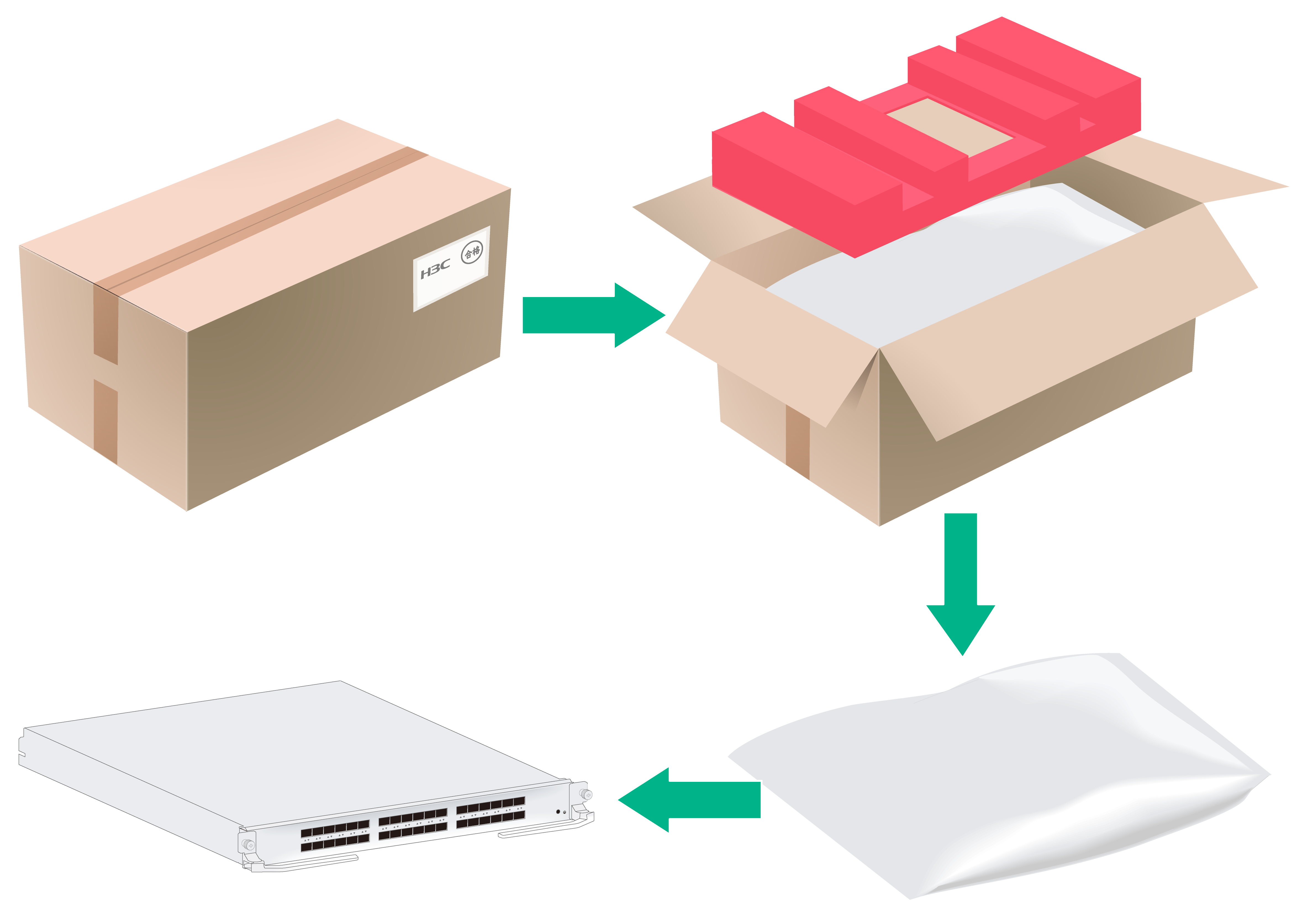
1. Use a utility knife to cut the straps on the carton. Open the carton and take the top foam cushion out of the carton.
2. Wear an ESD wrist strap and make sure the wrist strap is reliably grounded.
3. Take the component out of the anti-static bag.
4. Check the items in the carton against the packing list to verify that the items are as ordered.
Figure1-7 Unpacking a component packaged in a carton
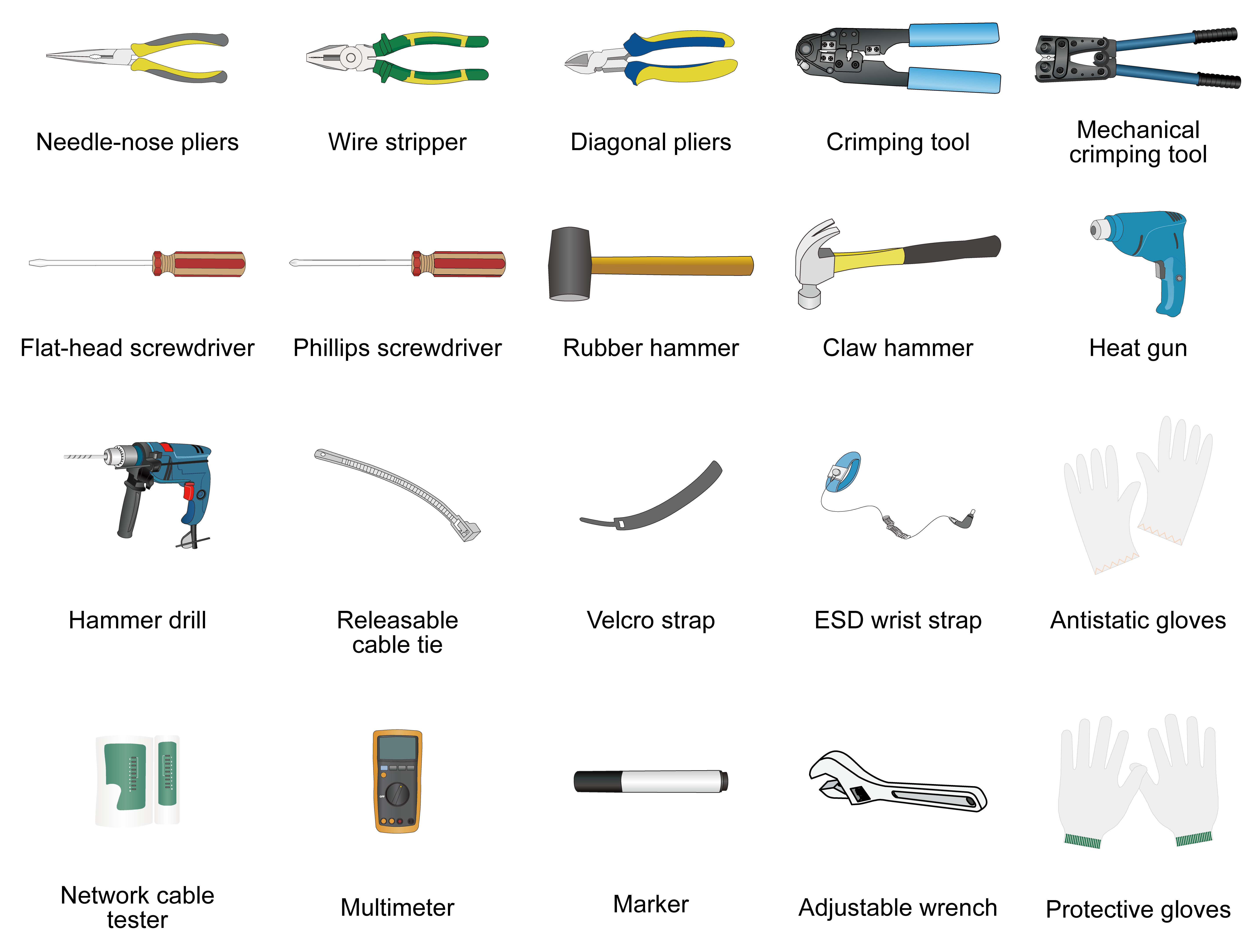
Installation tools
Installation tools are required when installing the router. Prepare installation tools as required. Figure1-8 provides installation tools for your reference.
Pre-installation checklist
Table1-7 Pre-installation checklist
|
Item |
Requirements |
Result |
|
|
Installation site |
Load bearing |
· The floor or ground at the installation site can support the combined weight of the router and the rack. · The slide rails can support the actual weight of the router. |
|
|
Space |
· There is a minimum clear height of 3 m (9.84 ft) (from the beam or the air duct to the floor) in the equipment room. · There is a minimum clearance of 1200 mm (47.24 in) between the rack and walls or other devices |
|
|
|
Rack |
· The rack has a good ventilation system. · The rack is sturdy enough to support the weight of the router and its installation accessories. · The rack has a size that can accommodate the router. · The front and rear of the rack are a minimum of 1200 mm (47.24 in) away from walls or other devices. |
|
|
|
Ventilation |
· The air inlet and outlet vents of the router are not blocked and adequate clearance is reserved around the air vents. · A good ventilation system is available at the installation site. |
|
|
|
Electricity safety |
· The power supply system can output enough power to maintain the device operation. · An uninterrupted power supply (UPS) is available. · The power-off switch in the equipment room is located so that the power can be immediately shut off when an accident occurs. |
|
|
|
Grounding |
· The grounding specifications for the equipment room comply with national and industry standards. · All communication devices in the equipment room are reliably grounded. · The working earthing and protective earthing systems of the communication power supplies use the same earthing conductor set with the protective earthing system of the communication devices. |
|
|
|
Temperature |
0°C to 45°C (32°F to 113°F). |
|
|
|
Humidity |
5% RH to 95% RH (noncondensing). |
|
|
|
Cleanliness |
· Dust concentration ≤ 3 × 10⁴ particles/m3 (no visible dust on the desktop in three days). · Dust (suspension) ≤ 0.2 mg/m3 · Dust (sedimentation) ≤ 1.5 mg/(m2h) · Sand ≤ 30 mg/m3 |
|
|
|
Harmful gas limit |
Harmful gases in the equipment room do not exceed the limit. |
|
|
|
ESD prevention |
· The router and rack are reliably grounded. · The equipment room is dust-proof. · The humidity and temperature are in the acceptable range. · An ESD wrist strap, an antistatic workbench, and Antistatic bags are available. · Instructions for preventing ESD damage have been read carefully. |
|
|
|
EMI prevention |
· Effective measures are taken for filtering interference from the power grid. · The working earthing of the router is away from the grounding facility of power equipment or lightning protection grounding facility. · The router is far away from radio transmitting stations, radar stations, and high-frequency devices. · Electromagnetic shielding, for example, shielded interface cables, is used as required. |
|
|
|
Lightning protection |
· The router is reliably grounded. · The grounding point of the AC power receptacle is reliably grounded. · (Optional.) Network port lightning arresters are available. |
|
|
|
Safety precautions |
· The router is far away from any moist areas and heat sources. · The power-off switch in the equipment room is located. |
|
|
|
Installation accessories |
Installation accessories supplied with the router are available. |
|
|
|
Reference |
· Documents shipped with the router are available. · Online documents are available. |
|
|
