- Table of Contents
-
- 03-IP Routing Volume
- 00-IP Routing Volume Organization
- 01-IP Routing Overview
- 02-Static Routing Configuration
- 03-RIP Configuration
- 04-OSPF Configuration
- 05-IS-IS Configuration
- 06-BGP Configuration
- 07-IPv6 Static Routing Configuration
- 08-IPv6 Ripng Configuration
- 09-IPv6 OSPFv3 Configuration
- 10-IPv6 IS-IS Configuration
- 11-IPv6 BGP Configuration
- 12-Routing Policy Configuration
- Related Documents
-
| Title | Size | Download |
|---|---|---|
| 09-IPv6 OSPFv3 Configuration | 242.42 KB |
Table of Contents
IPv6 OSPFv3 Configuration Task List
Configuring OSPFv3 Area Parameters
Configuring an OSPFv3 Stub Area
Configuring an OSPFv3 Virtual Link
Configuring OSPFv3 Network Types
Configuring the OSPFv3 Network Type for an Interface
Configuring an NBMA or P2MP Neighbor
Configuring OSPFv3 Routing Information Control
Configuring OSPFv3 Route Summarization
Configuring OSPFv3 Inbound Route Filtering
Configuring an OSPFv3 Cost for an Interface
Configuring the Maximum Number of OSPFv3 Load-balanced Routes
Configuring a Priority for OSPFv3
Configuring OSPFv3 Route Redistribution
Tuning and Optimizing OSPFv3 Networks
Configuring a DR Priority for an Interface
Ignoring MTU Check for DD Packets
Disable Interfaces from Sending OSPFv3 Packets
Enable the Logging of Neighbor State Changes
Displaying and Maintaining OSPFv3
Configuring OSPFv3 DR Election
Configuring OSPFv3 Route Redistribution
Troubleshooting OSPFv3 Configuration
No OSPFv3 Neighbor Relationship Established
When configuring OSPF, go to these sections for information you are interested in:
l IPv6 OSPFv3 Configuration Task List
l Configuring OSPFv3 Area Parameters
l Configuring OSPFv3 Network Types
l Configuring OSPFv3 Routing Information Control
l Tuning and Optimizing OSPFv3 Networks
l Displaying and Maintaining OSPFv3
l OSPFv3 Configuration Examples
l Troubleshooting OSPFv3 Configuration
![]()
l The term “router” in this document refers to a router in a generic sense or a Layer 3 switch.
l EA boards (such as LSQ1GP12EA and LSQ1TGX1EA) do not support IPv6 features.
Introduction to OSPFv3
OSPFv3 Overview
Open Shortest Path First version 3 (OSPFv3) supports IPv6 and complies with RFC2740 (OSPF for IPv6).
The same between OSPFv3 and OSPFv2:
l 32 bits router ID and area ID
l Packets: Hello, DD (Data Description), LSR (Link State Request), LSU (Link State Update), LSAck (Link State Acknowledgment)
l Mechanism for finding neighbors and establishing adjacencies
l Mechanism for LSA flooding and aging
Differences between OSPFv3 and OSPFv2:
l OSPFv3 runs on a per-link basis, instead of on a per-IP-subnet basis.
l OSPFv3 supports multiple instances per link.
l OSPFv3 identifies neighbors by Router ID, while OSPFv2 by IP address.
OSPFv3 Packets
OSPFv3 has also five types of packets: hello, DD, LSR, LSU, and LSAck.
The five packets have the same packet header, which different from the OSPFv2 packet header is only 16 bytes in length, has no authentication field, but is added with an Instance ID field to support multi-instance per link.
Figure 1-1 gives the OSPFv3 packet header.
Figure 1-1 OSPFv3 packet header
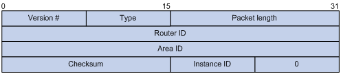
l Version #: Version of OSPF, which is 3 for OSPFv3.
l Type: Type of OSPF packet; Types 1 to 5 are hello, DD, LSR, LSU, and LSAck respectively.
l Packet Length: Packet length in bytes, including header.
l Instance ID: Instance ID for a link.
l 0: Reserved. It must be 0.
OSPFv3 LSA Types
OSPFv3 sends routing information in LSAs, which as defined in RFC2740 have the following types:
l Router-LSA: Originated by all routers. This LSA describes the collected states of the router's interfaces to an area. Flooded throughout a single area only.
l Network-LSA: Originated for broadcast and NBMA networks by the Designated Router. This LSA contains the list of routers connected to the network. Flooded throughout a single area only.
l Inter-Area-Prefix-LSA: Similar to Type 3 LSA of OSPFv2, originated by ABRs (Area Border Routers), and flooded throughout the LSA's associated area. Each Inter-Area-Prefix-LSA describes a route with IPv6 address prefix to a destination outside the area, yet still inside the AS (an inter-area route).
l Inter-Area-Router-LSA: Similar to Type 4 LSA of OSPFv2, originated by ABRs and flooded throughout the LSA's associated area. Each Inter-Area-Router-LSA describes a route to ASBR (Autonomous System Boundary Router).
l AS-external-LSA: Originated by ASBRs, and flooded throughout the AS (except Stub and NSSA areas). Each AS-external-LSA describes a route to another Autonomous System. A default route can be described by an AS external LSA.
l Link-LSA: A router originates a separate Link-LSA for each attached link. Link-LSAs have link-local flooding scope. Each Link-LSA describes the IPv6 address prefix of the link and Link-local address of the router.
l Intra-Area-Prefix-LSA: Each Intra-Area-Prefix-LSA contains IPv6 prefix information on a router, stub area or transit area information, and has area flooding scope. It was introduced because Router-LSAs and Network-LSAs contain no address information now.
Timers of OSPFv3
Timers in OSPFv3 include:
l OSPFv3 packet timer
l LSA delay timer
l SPF timer
OSPFv3 packet timer
Hello packets are sent periodically between neighboring routers for finding and maintaining neighbor relationships, or for DR/BDR election. The hello interval must be identical on neighboring interfaces. The smaller the hello interval, the faster the network convergence speed and the bigger the network load.
If a router receives no hello packet from a neighbor within a period, it will declare the peer is down. The period is called the dead interval.
After sending an LSA to its adjacency, a router waits for an acknowledgment from the adjacency. If no response is received after the retransmission interval elapses, the router will send again the LSA. The retransmission interval must be longer than the round-trip time of the LSA.
LSA delay time
Each LSA has an age in the local LSDB (incremented by 1 per second), but an LSA does not age on transmission. You need to add an LSA delay time into the age time before transmission, which is important for low-speed networks.
SPF timer
Whenever the LSDB changes, an SPF calculation happens. If recalculations become so frequent, a large amount of resources will be occupied. You can adjust the SPF calculation interval and delay time to protect networks from being overloaded due to frequent changes.
OSPFv3 Features Supported
l Basic features defined in RFC2740
l OSPFv3 stub area
l OSPFv3 multi-process, which enable a router to run multiple OSPFv3 processes
Related RFCs
l RFC2740: OSPF for IPv6
l RFC2328: OSPF Version 2
IPv6 OSPFv3 Configuration Task List
Complete the following tasks to configure OSPFv3:
|
Task |
Remarks |
|
|
Required |
||
|
Optional |
||
|
Optional |
||
|
Optional |
||
|
Optional |
||
|
Optional |
||
|
Optional |
||
|
Optional |
||
|
Configuring the Maximum Number of OSPFv3 Load-balanced Routes |
Optional |
|
|
Optional |
||
|
Optional |
||
|
Optional |
||
|
Optional |
||
|
Optional |
||
|
Optional |
||
|
Optional |
||
Enabling OSPFv3
Prerequisites
l Make neighboring nodes accessible with each other at the network layer.
l Enable IPv6 packet forwarding
Enabling OSPFv3
To enable an OSPFv3 process on a router, you need to enable the OSPFv3 process globally, assign the OSPFv3 process a router ID, and enable the OSPFv3 process on related interfaces.
A router ID uniquely identifies a router within an AS. Therefore, you need to specify a unique router ID for each OSPFv3 router within the AS to ensure normal operation. Note that if a router runs multiple OSPFv3 processes, you need to specify a unique router ID for each process.
An OSPFv3 process ID has only local significance. Therefore, process 1 on a router can exchange packets with process 2 on another router.
Follow these steps to enable OSPFv3:
|
To do… |
Use the command… |
Remarks |
|
Enter system view |
system-view |
— |
|
Enable an OSPFv3 process and enter its view |
ospfv3 [ process-id ] |
Required By default, no OSPFv3 process is enabled. |
|
Specify a router ID |
router-id router-id |
Required |
|
Enter interface view |
interface interface-type interface-number |
— |
|
Enable an OSPFv3 process on the interface |
ospfv3 process-id area area-id [ instance instance-id ] |
Required Not enabled by default |
Configuring OSPFv3 Area Parameters
The stub area and virtual link features of OSPFv3 are the same as OSPFv2.
Splitting an OSPFv3 AS into multiple areas reduces the number of LSAs and extends OSPFv3 applications. For those non-backbone areas residing on the AS boundary, you can configure them as stub areas to further reduce the size of routing tables and the number of LSAs.
Non-backbone areas exchange routing information via the backbone area. Therefore, the backbone and non-backbone areas, including the backbone itself must be contiguous. In practice, necessary physical links may not be available for such connectivity. You can configure virtual links to address the problem.
Prerequisites
l Enable IPv6 packet forwarding
l Configure OSPFv3 basic functions
Configuring an OSPFv3 Stub Area
Follow these steps to configure an OSPFv3 stub area:
|
To do… |
Use the command… |
Remarks |
|
Enter system view |
system-view |
— |
|
Enter OSPFv3 view |
ospfv3 [ process-id ] |
— |
|
Enter OSPFv3 area view |
area area-id |
— |
|
Configure the area as a stub area |
stub [ no-summary ] |
Required Not configured by default |
|
Specify a cost for the default route advertised to the stub area |
default-cost value |
Optional Defaults to 1 |
![]()
l You cannot remove an OSPFv3 area directly. Only when you remove all configurations in area view and all interfaces attached to the area become down, can the area be removed.
l All the routers attached to a stub area must be configured with the stub command. The keyword no-summary is only available on the ABR of the stub area.
l If you use the stub command with the keyword no-summary on an ABR, the ABR advertises a default route in an Inter-Area-Prefix-LSA into the stub area. No AS-external-LSA, Inter-Area-Prefix-LSA or Inter-Area-Router-LSA is advertised in the area. The stub area of this kind is also known as a totally stub area.
Configuring an OSPFv3 Virtual Link
You can configure a virtual link to maintain connectivity between a non-backbone area and the backbone, or in the backbone itself.
Follow these steps to configure a virtual link:
|
To do… |
Use the command… |
Remarks |
|
Enter system view |
system-view |
— |
|
Enter OSPFv3 view |
ospfv3 [ process-id ] |
— |
|
Enter OSPFv3 area view |
area area-id |
— |
|
Configure a virtual link |
vlink-peer router-id [ hello seconds | retransmit seconds | trans-delay seconds | dead seconds | instance instance-id ] * |
Required |
![]()
Both ends of a virtual link are ABRs that must be configured with the vlink-peer command.
Configuring OSPFv3 Network Types
OSPFv3 classifies networks into four types upon the link layer protocol:
By default, the default OSPFv3 interface network types vary with the link layer protocols of the interfaces:
l When the link layer protocol is PPP, OSPFv3 considers the network type as P2P by default.
l When the link layer protocol is Ethernet, OSPFv3 considers the network type as broadcast by default.
You can change the network type of an OSPFv3 interface as needed. For example:
l An NBMA network must be fully connected. That is, any two routers in the network must be directly reachable to each other through a virtual circuit. In the event no such direct link is available, you need to change the network type through a command.
l If direct connections are not available between some routers in an NBMA network, the type of interfaces associated should be configured as P2MP, or as P2P for interfaces with only one neighbor.
Prerequisites
Before configuring OSPFv3 network types, you have configured:
l IPv6 functions
l OSPFv3 basic functions
Configuring the OSPFv3 Network Type for an Interface
Follow these steps to configure the OSPFv3 network type for an interface:
|
To do… |
Use the command… |
Remarks |
|
Enter system view |
system-view |
— |
|
Enter interface view |
interface interface-type interface-number |
— |
|
Configure a network type for the OSPFv3 interface |
ospfv3 network-type { broadcast | nbma | p2mp [ non-broadcast ] | p2p } [ instance instance-id ] |
Optional The network type of an interface depends on the media type of the interface. |
Configuring an NBMA or P2MP Neighbor
For NBMA and P2MP interfaces (only when in unicast mode), you need to specify the link-local IP addresses of their neighbors because such interfaces cannot find neighbors via broadcasting Hello packets. You can also specify DR priorities for neighbors.
Follow these steps to configure an NBMA or P2MP (unicast) neighbor and its DR priority:
|
To do… |
Use the command… |
Remarks |
|
Enter system view |
system-view |
— |
|
Enter interface view |
interface interface-type interface-number |
— |
|
Specify an NBMA or P2MP (unicast) neighbor and its DR priority |
ospfv3 peer ipv6-address [ dr-priority dr-priority ] [ instance instance-id ] |
Required |
Configuring OSPFv3 Routing Information Control
This section is to configure the control of OSPF routing information advertisement and reception, and redistribution from other protocols.
Prerequisites
l Enable IPv6 packet forwarding
l Configure OSPFv3 basic functions
Configuring OSPFv3 Route Summarization
If contiguous network segments exist in an area, you can use the abr-summary command to summarize them into one network segment on the ABR. The ABR will advertise only the summary route. Any LSA falling into the specified network segment will not be advertised, reducing the LSDB size in other areas.
Follow these steps to configure route summarization:
|
To do… |
Use the command… |
Remarks |
|
Enter system view |
system-view |
— |
|
Enter OSPFv3 view |
ospfv3 [ process-id ] |
— |
|
Enter OSPFv3 area view |
area area-id |
— |
|
Configure a summary route |
abr-summary ipv6-address prefix-length [ not-advertise ] |
Required Not configured by default |
![]()
The abr-summary command takes effect on ABRs only.
Configuring OSPFv3 Inbound Route Filtering
You can configure OSPFv3 to filter routes that are computed from received LSAs according to some rules.
Follow these steps to configure OSPFv3 inbound route filtering:
|
To do… |
Use the command… |
Remarks |
|
Enter system view |
system-view |
— |
|
Enter OSPFv3 view |
ospfv3 [ process-id ] |
— |
|
Configure inbound route filtering |
filter-policy { acl-number | ipv6-prefix ipv6-prefix-name } import |
Required Not configured by default |
![]()
Use of the filter-policy import command can only filter routes computed by OSPFv3. Only routes not filtered out can be added into the local routing table.
Configuring an OSPFv3 Cost for an Interface
You can configure an OSPFv3 cost for an interface with one of the following two methods:
l Configure the cost value in interface view.
l Configure a bandwidth reference value for the interface, and OSPFv3 computes the cost automatically based on the bandwidth reference value: Interface OSPFv3 cost = Bandwidth reference value/Interface bandwidth. If the calculated cost is greater than 65535, the value of 65535 is used.
If the cost value is not configured for an interface, OSPFv3 computes the interface cost value automatically
Follow these steps to configure an OSPFv3 cost for an interface:
|
To do… |
Use the command… |
Remarks |
|
Enter system view |
system-view |
— |
|
Enter interface view |
interface interface-type interface-number |
— |
|
Configure an OSPFv3 cost for the interface |
ospfv3 cost value [ instance instance-id ] |
Optional By default, OSPFv3 computes an interface’s cost according to its bandwidth. The cost value defaults to 1 for VLAN interfaces of switches. |
Follow these steps to configure a bandwidth reference value:
|
To do… |
Use the command… |
Remarks |
|
Enter system view |
system-view |
— |
|
Enter OSPFv3 view |
ospfv3 [ process-id ] |
— |
|
Configure a bandwidth reference value |
bandwidth-reference value |
Optional 100 Mbps by default |
Configuring the Maximum Number of OSPFv3 Load-balanced Routes
If multiple equal-cost routes to a destination are available, enabling load balancing among these routes can improve link utilization.
Follow these steps to configure the maximum number of load-balanced routes:
|
To do… |
Use the command… |
Remarks |
|
Enter system view |
system-view |
— |
|
Enter OSPFv3 view |
ospfv3 [ process-id ] |
— |
|
Specify the maximum number of load-balanced routes |
maximum load-balancing maximum |
Optional 4 by default |
Configuring a Priority for OSPFv3
A router may run multiple routing protocols. The system assigns a priority for each protocol. When these routing protocols find the same route, the route found by the protocol with the highest priority is selected.
Follow these steps to configure a priority for OSPFv3:
|
To do… |
Use the command… |
Remarks |
|
Enter system view |
system-view |
— |
|
Enter OSPFv3 view |
ospfv3 [ process-id ] |
— |
|
Configure a priority for OSPFv3 |
preference [ ase ] [ route-policy route-policy-name ] preference |
Optional By default, the priority of OSPFv3 internal routes is 10, and priority of OSPFv3 external routes is 150. |
Configuring OSPFv3 Route Redistribution
Follow these steps to configure OSPFv3 route redistribution:
|
To do… |
Use the command… |
Remarks |
|
Enter system view |
system-view |
— |
|
Enter OSPFv3 view |
ospfv3 [ process-id ] |
— |
|
Specify a default cost for redistributed routes |
default cost value |
Optional Defaults to 1 |
|
Redistribute routes from another protocol, or another OSPFv3 process |
import-route { isisv6 process-id | ospfv3 process-id | ripng process-id | bgp4+ [ allow-ibgp ] | direct | static } [ cost value | type type | route-policy route-policy-name ] * |
Required Not configured by default |
|
Inject a default route |
default-route-advertise [ always | cost cost | type type | route-policy route-policy-name ] * |
Optional Not injected by default |
|
Filter redistributed routes |
filter-policy { acl6-number | ipv6-prefix ipv6-prefix-name } export [ isisv6 process-id | ospfv3 process-id | ripng process-id | bgp4+ | direct | static ] |
Optional Not configured by default |
![]()
l Executing the import-route or default-route-advertise command on a router makes it become an ASBR,.
l You can only inject and advertise a default route using the default-route-advertise command.
l Since OSPFv3 is a link state routing protocol, it cannot directly filter LSAs to be advertised. Therefore, you need to filter redistributed routes first, and thus only routes that are not filtered out can be advertised in LSAs into the routing domain.
l Use of the filter-policy export command filters routes redistributed with the import-route command. If the import-route command is not configured, executing the filter-policy export command does not take effect.
Tuning and Optimizing OSPFv3 Networks
This section describes configurations of OSPFv3 timers, interface DR priority, MTU check ignorance for DD packets, and disabling interfaces from sending OSPFv3 packets.
OSPFv3 timers:
l Packet timer: Specified to adjust topology convergence speed and network load
l LSA delay timer: Specified especially for low-speed links
l SPF timer: Specified to protect networks from being over-loaded due to frequent network changes.
For a broadcast network, you can configure DR priorities for interfaces to affect DR/BDR election.
By disabling an interface from sending OSPFv3 packets, you can make other routers on the network obtain no information from the interface.
Prerequisites
l Enable IPv6 packet forwarding
l Configure OSPFv3 basic functions
Configuring OSPFv3 Timers
Follow these steps to configure OSPFv3 timers:
|
Use the command… |
Remarks |
|
|
Enter system view |
system-view |
— |
|
Enter interface view |
interface interface-type interface-number |
— |
|
Configure the hello interval |
ospfv3 timer hello seconds [ instance instance-id ] |
Optional Defaults to 10 seconds on P2P, broadcast interfaces. |
|
Specify the poll interval |
ospfv3 timer poll seconds [ instance instance-id ] |
Optional The poll interval defaults to 120 seconds. |
|
Configure the dead interval |
ospfv3 timer dead seconds [ instance instance-id ] |
Optional Defaults to 40 seconds on P2P, broadcast interfaces. |
|
Configure the LSA retransmission interval |
ospfv3 timer retransmit interval [ instance instance-id ] |
Optional Defaults to 5 seconds. |
|
Configure the LSA transmission delay |
ospfv3 trans-delay seconds [ instance instance-id ] |
Optional Defaults to 1 second. |
|
Return to system view |
quit |
— |
|
Enter OSPFv3 view |
ospfv3 [ process-id ] |
— |
|
Configure the SPF timers |
spf timers delay-interval hold-interval |
Optional By default, delay-interval is 5 seconds, and hold-interval is 10 seconds. |
![]()
l The dead interval set on neighboring interfaces cannot be too short. Otherwise, a neighbor is easily considered down.
l The LSA retransmission interval cannot be too short; otherwise, unnecessary retransmissions occur.
Configuring a DR Priority for an Interface
Follow these steps to configure a DR priority for an interface:
|
To do… |
Use the command… |
Remarks |
|
Enter system view |
system-view |
— |
|
Enter interface view |
interface interface-type interface-number |
— |
|
Configure a DR priority |
ospfv3 dr-priority priority [ instance instance-id ] |
Optional Defaults to 1 |
![]()
The DR priority of an interface determines the interface’s qualification in DR election. Interfaces having the priority 0 cannot become a DR or BDR.
Ignoring MTU Check for DD Packets
When LSAs are few in DD packets, it is unnecessary to check the MTU in DD packets in order to improve efficiency.
Follow these steps to ignore MTU check for DD packets:
|
To do… |
Use the command… |
Remarks |
|
Enter system view |
system-view |
— |
|
Enter interface view |
interface interface-type interface-number |
— |
|
Ignore MTU check for DD packets |
ospfv3 mtu-ignore [ instance instance-id ] |
Required Not ignored by default |
Disable Interfaces from Sending OSPFv3 Packets
Follow these steps to disable interfaces from sending OSPFv3 packets:
|
To do… |
Use the command… |
Remarks |
|
Enter system view |
system-view |
— |
|
Enter OSPFv3 view |
ospfv3 [ process-id ] |
— |
|
Disable interfaces from sending OSPFv3 packets |
silent-interface { interface-type interface-number | all } |
Required Not disabled by default |
![]()
l Multiple OSPFv3 processes can disable the same interface from sending OSPFv3 packets. Using the silent-interface command disables only the interfaces associated with the current process.
l After an OSPF interface is set to silent, direct routes of the interface can still be advertised in Intra-Area-Prefix-LSAs via other interfaces, but other OSPFv3 packets cannot be advertised. Therefore, no neighboring relationship can be established on the interface. This feature can enhance the adaptability of OSPFv3 networking.
Enable the Logging of Neighbor State Changes
Follow these steps to enable the logging of neighbor state changes:
|
To do… |
Use the command… |
Remarks |
|
Enter system view |
system-view |
— |
|
Enter OSPFv3 view |
ospfv3 [ process-id ] |
— |
|
Enable the logging of neighbor state changes |
log-peer-change |
Required Enabled by default |
Displaying and Maintaining OSPFv3
|
To do… |
Use the command… |
Remarks |
|
Display OSPFv3 debugging state information |
display debugging ospfv3 |
Available in any view |
|
Display OSPFv3 process brief information |
display ospfv3 [ process-id ] |
|
|
Display OSPFv3 interface information |
display ospfv3 interface [ interface-type interface-number | statistic ] |
|
|
Display OSPFv3 LSDB information |
display ospfv3 [ process-id ] lsdb [ [ external | inter-prefix | inter-router | intra-prefix | link | network | router ] [ link-state-id ] [ originate-router router-id ] | total ] |
|
|
Display OSPFv3 LSDB statistics |
display ospfv3 lsdb statistic |
|
|
Display OSPFv3 neighbor information |
display ospfv3 [ process-id ] [ area area-id ] peer [ [ interface-type interface-number ] [ verbose ] | peer-router-id ] |
|
|
Display OSPFv3 neighbor statistics |
display ospfv3 peer statistic |
|
|
Display OSPFv3 routing table information |
display ospfv3 [ process-id ] routing [ ipv6-address prefix-length | ipv6-address/prefix-length | abr-routes | asbr-routes | all | statistics ] |
|
|
Display OSPFv3 area topology information |
display ospfv3 [ process-id ] topology [ area area-id ] |
|
|
Display OSPFv3 virtual link information |
display ospfv3 [ process-id ] vlink |
|
|
Display OSPFv3 next hop information |
display ospfv3 [ process-id ] next-hop |
|
|
Display OSPFv3 link state request list information |
display ospfv3 [ process-id ] request-list [ { external | inter-prefix | inter-router | intra-prefix | link | network | router } [ link-state-id ] [ originate-router ip-address ] | statistics ] |
|
|
Display OSPFv3 link state retransmission list information |
display ospfv3 [ process-id ] retrans-list [ { external | inter-prefix | inter-router | intra-prefix | link | network | router } [ link-state-id ] [ originate-router ip-address ] | statistics ] |
|
|
Display OSPFv3 statistics |
display ospfv3 statistics |
OSPFv3 Configuration Examples
Configuring OSPFv3 Areas
Network requirements
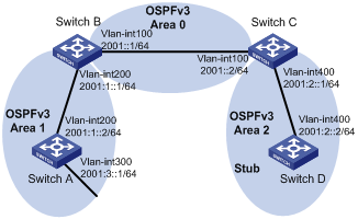
In the following figure, all switches run OSPFv3. The AS is split into three areas, in which, Switch B and Switch C act as ABRs to forward routing information between areas.
It is required to configure Area 2 as a stub area to reduce LSAs in the area without affecting route reachability.
Network diagram
Figure 1-2 Network diagram for OSPFv3 area configuration
Configuration procedure
1) Configure IPv6 addresses for interfaces (omitted)
2) Configure OSPFv3 basic functions
# Configure Switch A.
<SwitchA> system-view
[SwitchA] ipv6
[SwitchA] ospfv3
[SwitchA-ospfv3-1] router-id 1.1.1.1
[SwitchA-ospfv3-1] quit
[SwitchA] interface vlan-interface 300
[SwitchA-Vlan-interface300] ospfv3 1 area 1
[SwitchA-Vlan-interface300] quit
[SwitchA] interface vlan-interface 200
[SwitchA-Vlan-interface200] ospfv3 1 area 1
[SwitchA-Vlan-interface200] quit
# Configure Switch B.
<SwitchB> system-view
[SwitchB] ipv6
[SwitchB] ospfv3
[SwitchB-ospf-1] router-id 2.2.2.2
[SwitchB-ospf-1] quit
[SwitchB] interface vlan-interface 100
[SwitchB-Vlan-interface100] ospfv3 1 area 0
[SwitchB-Vlan-interface100] quit
[SwitchB] interface vlan-interface 200
[SwitchB-Vlan-interface200] ospfv3 1 area 1
[SwitchB-Vlan-interface200] quit
# Configure Switch C.
<SwitchC> system-view
[SwitchC] ipv6
[SwitchC] ospfv3
[SwitchC-ospfv3-1] router-id 3.3.3.3
[SwitchC-ospfv3-1] quit
[SwitchC] interface vlan-interface 100
[SwitchC-Vlan-interface100] ospfv3 1 area 0
[SwitchC-Vlan-interface100] quit
[SwitchC] interface vlan-interface 400
[SwitchC-Vlan-interface400] ospfv3 1 area 2
[SwitchC-Vlan-interface400] quit
# Configure Switch D.
<SwitchD> system-view
[SwitchD] ipv6
[SwitchD] ospfv3
[SwitchD-ospfv3-1] router-id 4.4.4.4
[SwitchD-ospfv3-1] quit
[SwitchD] interface Vlan-interface 400
[SwitchD-Vlan-interface400] ospfv3 1 area 2
[SwitchD-Vlan-interface400] quit
# Display OSPFv3 neighbor information on Switch B.
[SwitchB] display ospfv3 peer
OSPFv3 Area ID 0.0.0.0 (Process 1)
----------------------------------------------------------------------
Neighbor ID Pri State Dead Time Interface Instance ID
3.3.3.3 1 Full/DR 00:00:39 Vlan100 0
OSPFv3 Area ID 0.0.0.1 (Process 1)
----------------------------------------------------------------------
Neighbor ID Pri State Dead Time Interface Instance ID
1.1.1.1 1 Full/Backup 00:00:38 Vlan200 0
# Display OSPFv3 neighbor information on Switch C.
[SwitchC] display ospfv3 peer
OSPFv3 Area ID 0.0.0.0 (Process 1)
----------------------------------------------------------------------
Neighbor ID Pri State Dead Time Interface Instance ID
2.2.2.2 1 Full/Backup 00:00:39 Vlan100 0
OSPFv3 Area ID 0.0.0.2 (Process 1)
----------------------------------------------------------------------
Neighbor ID Pri State Dead Time Interface Instance ID
4.4.4.4 1 Full/DR 00:00:38 Vlan400 0
# Display OSPFv3 routing table information on Switch D.
[SwitchD] display ospfv3 routing
E1 - Type 1 external route, IA - Inter area route, I - Intra area route
E2 - Type 2 external route, * - Seleted route
OSPFv3 Router with ID (4.4.4.4) (Process 1)
------------------------------------------------------------------------
*Destination: 2001::/64
Type : IA Cost : 2
NextHop : FE80::F40D:0:93D0:1 Interface: Vlan400
*Destination: 2001:1::/64
Type : IA Cost : 3
NextHop : FE80::F40D:0:93D0:1 Interface: Vlan400
*Destination: 2001:2::/64
Type : I Cost : 1
NextHop : directly-connected Interface: Vlan400
*Destination: 2001:3::/64
Type : IA Cost : 4
NextHop : FE80::F40D:0:93D0:1 Interface: Vlan400
3) Configure Area 2 as a stub area
# Configure Switch D
[SwitchD] ospfv3
[SwitchD-ospfv3-1] area 2
[SwitchD-ospfv3-1-area-0.0.0.2] stub
# Configure Switch C, and specify the cost of the default route sent to the stub area as 10.
[SwitchC] ospfv3
[SwitchC-ospfv3-1] area 2
[SwitchC-ospfv3-1-area-0.0.0.2] stub
[SwitchC-ospfv3-1-area-0.0.0.2] default-cost 10
# Display OSPFv3 routing table information on Switch D. You can find a default route is added, and its cost is the cost of a direct route plus the configured cost.
[SwitchD] display ospfv3 routing
E1 - Type 1 external route, IA - Inter area route, I - Intra area route
E2 - Type 2 external route, * - Seleted route
OSPFv3 Router with ID (4.4.4.4) (Process 1)
------------------------------------------------------------------------
*Destination: ::/0
Type : IA Cost : 11
NextHop : FE80::F40D:0:93D0:1 Interface: Vlan400
*Destination: 2001::/64
Type : IA Cost : 2
NextHop : FE80::F40D:0:93D0:1 Interface: Vlan400
*Destination: 2001:1::/64
Type : IA Cost : 3
NextHop : FE80::F40D:0:93D0:1 Interface: Vlan400
*Destination: 2001:2::/64
Type : I Cost : 1
NextHop : directly-connected Interface: Vlan400
*Destination: 2001:3::/64
Type : IA Cost : 4
NextHop : FE80::F40D:0:93D0:1 Interface: Vlan400
4) Configure Area 2 as a totally stub area
# Configure Area 2 as a totally stub area on Switch C.
[SwitchC-ospfv3-1-area-0.0.0.2] stub no-summary
# Display OSPFv3 routing table information on Switch D. You can find route entries are reduced. All non-direct routes are removed except the default route.
[SwitchD] display ospfv3 routing
E1 - Type 1 external route, IA - Inter area route, I - Intra area route
E2 - Type 2 external route, * - Seleted route
OSPFv3 Router with ID (4.4.4.4) (Process 1)
------------------------------------------------------------------------
*Destination: ::/0
Type : IA Cost : 11
NextHop : FE80::F40D:0:93D0:1 Interface: Vlan400
*Destination: 2001:2::/64
Type : I Cost : 1
NextHop : directly-connected Interface: Vlan400
Configuring OSPFv3 DR Election
Network requirements
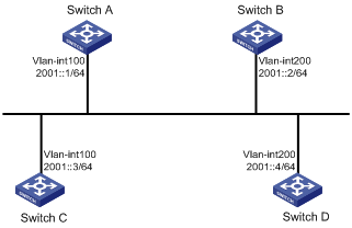
In the following figure:
l The priority of Switch A is 100, the highest priority on the network, so it will be the DR.
l The priority of Switch C is 2, the second highest priority on the network, so it will be the BDR.
l The priority of Switch B is 0, so it cannot become the DR.
l Router D has the default priority 1.
Network diagram
Figure 1-3 Network diagram for OSPFv3 DR election configuration
Configuration procedure
1) Configure IPv6 addresses for interfaces (omitted)
2) Configure OSPFv3 basic functions
# Configure Switch A.
<SwitchA> system-view
[SwitchA] ipv6
[SwitchA] ospfv3
[SwitchA-ospfv3-1] router-id 1.1.1.1
[SwitchA-ospfv3-1] quit
[SwitchA] interface vlan-interface 100
[SwitchA-Vlan-interface100] ospfv3 1 area 0
[SwitchA-Vlan-interface100] quit
# Configure Switch B.
<SwitchB> system-view
[SwitchB] ipv6
[SwitchB] ospfv3
[SwitchB-ospfv3-1] router-id 2.2.2.2
[SwitchB-ospfv3-1] quit
[SwitchB] interface vlan-interface 200
[SwitchB-Vlan-interface200] ospfv3 1 area 0
[SwitchB-Vlan-interface200] quit
# Configure Switch C.
<SwitchC> system-view
[SwitchC] ipv6
[SwitchC] ospfv3
[SwitchC-ospfv3-1] router-id 3.3.3.3
[SwitchC-ospfv3-1] quit
[SwitchC] interface vlan-interface 100
[SwitchC-Vlan-interface100] ospfv3 1 area 0
[SwitchC-Vlan-interface100] quit
# Configure Switch D.
<SwitchD> system-view
[SwitchD] ipv6
[SwitchD] ospfv3
[SwitchD-ospfv3-1] router-id 4.4.4.4
[SwitchD-ospfv3-1] quit
[SwitchD] interface vlan-interface 200
[SwitchD-Vlan-interface200] ospfv3 1 area 0
[SwitchD-Vlan-interface200] quit
# Display neighbor information on Switch A. You can find the switches have the same default DR priority 1. In this case, the switch with the highest Router ID is elected as the DR. Therefore, Switch D is the DR, and Switch C is the BDR.
[SwitchA] display ospfv3 peer
OSPFv3 Area ID 0.0.0.0 (Process 1)
----------------------------------------------------------------------
Neighbor ID Pri State Dead Time Interface Instance ID
2.2.2.2 1 2-Way/DROther 00:00:36 Vlan200 0
3.3.3.3 1 Full/Backup 00:00:35 Vlan100 0
4.4.4.4 1 Full/DR 00:00:33 Vlan200 0
# Display neighbor information on Switch D. You can find the neighbor states are all full.
[SwitchD] display ospfv3 peer
OSPFv3 Area ID 0.0.0.0 (Process 1)
----------------------------------------------------------------------
Neighbor ID Pri State Dead Time Interface Instance ID
1.1.1.1 1 Full/DROther 00:00:30 Vlan100 0
2.2.2.2 1 Full/DROther 00:00:37 Vlan200 0
3.3.3.3 1 Full/Backup 00:00:31 Vlan100 0
3) Configure DR priorities for interfaces.
# Configure the DR priority of VLAN-interface 100 as 100 on Switch A.
[SwitchA] interface Vlan-interface 100
[SwitchA-Vlan-interface100] ospfv3 dr-priority 100
[SwitchA-Vlan-interface100] quit
# Configure the DR priority of VLAN-interface 200 as 0 on Switch B.
[SwitchB] interface vlan-interface 200
[SwitchB-Vlan-interface200] ospfv3 dr-priority 0
[SwitchB-Vlan-interface200] quit
# Configure the DR priority of VLAN-interface 100 of Switch C as 2.
[SwitchC] interface Vlan-interface 100
[SwitchC-Vlan-interface100] ospfv3 dr-priority 2
[SwitchC-Vlan-interface100] quit
# Display neighbor information on Switch A. You can find DR priorities have been updated, but the DR and BDR are not changed.
[SwitchA] display ospfv3 peer
OSPFv3 Area ID 0.0.0.0 (Process 1)
----------------------------------------------------------------------
Neighbor ID Pri State Dead Time Interface Instance ID
2.2.2.2 0 2-Way/DROther 00:00:38 Vlan200 0
3.3.3.3 2 Full/Backup 00:00:32 Vlan100 0
4.4.4.4 1 Full/DR 00:00:36 Vlan200 0
# Display neighbor information on Switch D. You can find Switch D is still the DR.
[SwitchD] display ospfv3 peer
OSPFv3 Area ID 0.0.0.0 (Process 1)
----------------------------------------------------------------------
Neighbor ID Pri State Dead Time Interface Instance ID
1.1.1.1 100 Full/DROther 00:00:33 Vlan100 0
2.2.2.2 0 Full/DROther 00:00:36 Vlan200 0
3.3.3.3 2 Full/Backup 00:00:40 Vlan100 0
4) Restart DR/BDR election
# Use the shutdown and undo shutdown commands on interfaces to restart DR/BDR election (omitted).
# Display neighbor information on Switch A. You can find Switch C becomes the BDR.
[SwitchA] display ospfv3 peer
OSPFv3 Area ID 0.0.0.0 (Process 1)
----------------------------------------------------------------------
Neighbor ID Pri State Dead Time Interface Instance ID
2.2.2.2 0 Full/DROther 00:00:31 Vlan200 0
3.3.3.3 2 Full/Backup 00:00:39 Vlan100 0
4.4.4.4 1 Full/DROther 00:00:37 Vlan200 0
# Display neighbor information on Switch D. You can find Switch A becomes the DR.
[SwitchD] display ospfv3 peer
OSPFv3 Area ID 0.0.0.0 (Process 1)
----------------------------------------------------------------------
Neighbor ID Pri State Dead Time Interface Instance ID
1.1.1.1 100 Full/DR 00:00:34 Vlan100 0
2.2.2.2 0 2-Way/DROther 00:00:34 Vlan200 0
3.3.3.3 2 Full/Backup 00:00:32 Vlan100 0
Configuring OSPFv3 Route Redistribution
Network requirements
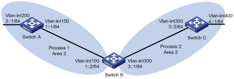
l Switch A, Switch B, and Switch C are in Area 2.
l OSPFv3 process 1 and OSPFv3 process 2 are enabled on Switch B. Switch B communicates with Switch A and Switch C through OSPFv3 process 1 and OSPFv3 process 2 respectively.
l Configure OSPFv3 process 2 to redistribute direct routes and the routes from OSPFv3 process 1 on Switch B and set the default metric for redistributed routes to 3. Thus, Switch C can learn the routes destined for 1::0/64 and 2::0/64, while Switch A cannot learn the routes destined for 3::0/64 or 4::0/64.
Network diagram
Figure 1-4 Network diagram for OSPFv3 route redistribution
Configuration procedure
1) Configure IPv6 addresses for interfaces (omitted)
2) Configure OSPFv3 basic functions
# Enable OSPFv3 process 1 on Switch A.
<SwitchA> system-view
[SwitchA] ipv6
[SwitchA] ospfv3 1
[SwitchA-ospfv3-1] router-id 1.1.1.1
[SwitchA-ospfv3-1] quit
[SwitchA] interface vlan-interface 100
[SwitchA-Vlan-interface100] ospfv3 1 area 2
[SwitchA-Vlan-interface100] quit
[SwitchA] interface vlan-interface 200
[SwitchA-Vlan-interface200] ospfv3 1 area 2
[SwitchA-Vlan-interface200] quit
# Enable OSPFv3 process 1 and OSPFv3 process 2 on Switch B.
<SwitchB> system-view
[SwitchB] ipv6
[SwitchB] ospfv3 1
[SwitchB-ospfv3-1] router-id 2.2.2.2
[SwitchB-ospfv3-1] quit
[SwitchB] interface vlan-interface 100
[SwitchB-Vlan-interface100] ospfv3 1 area 2
[SwitchB-Vlan-interface100] quit
[SwitchB] ospfv3 2
[SwitchB-ospfv3-2] router-id 3.3.3.3
[SwitchB-ospfv3-2] quit
[SwitchB] interface vlan-interface 300
[SwitchB-Vlan-interface300] ospfv3 2 area 2
[SwitchB-Vlan-interface300] quit
# Enable OSPFv3 process 2 on Switch C.
<SwitchC> system-view
[SwitchC] ipv6
[SwitchC] ospfv3 2
[SwitchC-ospfv3-2] router-id 4.4.4.4
[SwitchC-ospfv3-2] quit
[SwitchC] interface vlan-interface 300
[SwitchC-Vlan-interface300] ospfv3 2 area 2
[SwitchC-Vlan-interface300] quit
[SwitchC] interface vlan-interface 400
[SwitchC-Vlan-interface400] ospfv3 2 area 2
[SwitchC-Vlan-interface400] quit
# Display the routing table of Switch C.
[SwitchC] display ipv6 routing-table
Routing Table :
Destinations : 6 Routes : 6
Destination: ::1/128 Protocol : Direct
NextHop : ::1 Preference: 0
Interface : InLoop0 Cost : 0
Destination: 3::/64 Protocol : Direct
NextHop : 3::2 Preference: 0
Interface : Vlan300 Cost : 0
Destination: 3::2/128 Protocol : Direct
NextHop : ::1 Preference: 0
Interface : InLoop0 Cost : 0
Destination: 4::/64 Protocol : Direct
NextHop : 4::1 Preference: 0
Interface : Vlan400 Cost : 0
Destination: 4::1/128 Protocol : Direct
NextHop : ::1 Preference: 0
Interface : InLoop0 Cost : 0
Destination: FE80::/10 Protocol : Direct
NextHop : :: Preference: 0
Interface : NULL0 Cost : 0
3) Configure OSPFv3 route redistribution
# Configure OSPFv3 process 2 to redistribute direct routes and the routes from OSPFv3 process 1 on Switch B.
[SwitchB] ospfv3 2
[SwitchB-ospfv3-2] default cost 3
[SwitchB-ospfv3-2] import-route ospfv3 1
[SwitchB-ospfv3-2] import-route direct
[SwitchB-ospfv3-2] quit
# Display the routing table of Switch C.
[SwitchC] display ipv6 routing-table
Routing Table :
Destinations : 8 Routes : 8
Destination: ::1/128 Protocol : Direct
NextHop : ::1 Preference: 0
Interface : InLoop0 Cost : 0
Destination: 1::/64 Protocol : OSPFv3
NextHop : FE80::200:CFF:FE01:1C03 Preference: 150
Interface : Vlan300 Cost : 3
Destination: 2::/64 Protocol : OSPFv3
NextHop : FE80::200:CFF:FE01:1C03 Preference: 150
Interface : Vlan300 Cost : 3
Destination: 3::/64 Protocol : Direct
NextHop : 3::2 Preference: 0
Interface : Vlan300 Cost : 0
Destination: 3::2/128 Protocol : Direct
NextHop : ::1 Preference: 0
Interface : InLoop0 Cost : 0
Destination: 4::/64 Protocol : Direct
NextHop : 4::1 Preference: 0
Interface : Vlan400 Cost : 0
Destination: 4::1/128 Protocol : Direct
NextHop : ::1 Preference: 0
Interface : InLoop0 Cost : 0
Destination: FE80::/10 Protocol : Direct
NextHop : :: Preference: 0
Interface : NULL0 Cost : 0
Troubleshooting OSPFv3 Configuration
No OSPFv3 Neighbor Relationship Established
Symptom
No OSPF neighbor relationship can be established.
Analysis
If the physical link and lower protocol work well, check OSPF parameters configured on interfaces. The two neighboring interfaces must have the same parameters, such as the area ID, network segment and mask and network type. If the network type is broadcast, at least one interface must have a DR priority higher than 0.
Process steps
1) Display neighbor information using the display ospfv3 peer command.
2) Display OSPFv3 interface information using the display ospfv3 interface command.
3) Ping the neighbor router’s IP address to check connectivity.
4) Check OSPF timers. The dead interval on an interface must be at least four times the hello interval.
5) On a broadcast network, at least one interface must have a DR priority higher than 0.
Incorrect Routing Information
Symptom
OSPFv3 cannot find routes to other areas.
Analysis
The backbone area must maintain connectivity to all other areas. If a router connects to more than one area, at least one area must be connected to the backbone. The backbone cannot be configured as a Stub area.
In a Stub area, all routers cannot receive external routes, and all interfaces connected to the Stub area must be associated with the Stub area.
Solution
1) Use the display ospfv3 peer command to display OSPFv3 neighbors.
2) Use the display ospfv3 interface command to display OSPFv3 interface information.
3) Use the display ospfv3 lsdb command to display Link State Database information to check integrity.
4) Display information about area configuration using the display current-configuration configuration command. If more than two areas are configured, at least one area is connected to the backbone.
5) In a Stub area, all routers are configured with the stub command.
6) If a virtual link is configured, use the display ospf vlink command to check the neighbor state.
