- Table of Contents
-
- 03-IP Routing Volume
- 00-IP Routing Volume Organization
- 01-IP Routing Overview
- 02-Static Routing Configuration
- 03-RIP Configuration
- 04-OSPF Configuration
- 05-IS-IS Configuration
- 06-BGP Configuration
- 07-IPv6 Static Routing Configuration
- 08-IPv6 Ripng Configuration
- 09-IPv6 OSPFv3 Configuration
- 10-IPv6 IS-IS Configuration
- 11-IPv6 BGP Configuration
- 12-Routing Policy Configuration
- Related Documents
-
| Title | Size | Download |
|---|---|---|
| 06-BGP Configuration | 772.52 KB |
Table of Contents
Settlements for Problems in Large Scale BGP Networks
Configuring BGP Basic Functions
Specifying the Source Interface for TCP Connections
Allowing Establishment of eBGP Connection to a Non Directly Connected Peer/Peer Group
Configuring BGP Route Redistribution
Enabling Default Route Redistribution into BGP
Controlling Route Distribution and Reception
Configuring BGP Route Summarization
Advertising a Default Route to a Peer or Peer Group
Configuring BGP Route Distribution/Reception Filtering Policies
Enabling BGP and IGP Route Synchronization
Limiting Prefixes Received from a Peer/Peer Group
Configuring BGP Route Dampening
Configuring BGP Route Attributes
Specifying a Preferred Value for Routes Received
Configuring Preferences for BGP Routes
Configure the Default Local Preference
Configuring the Next Hop Attribute
Configuring the AS-PATH Attribute
Tuning and Optimizing BGP Networks
Configuring BGP Keepalive Interval and Holdtime
Configuring the Interval for Sending the Same Update
Enabling Quick eBGP Session Reestablishment
Enabling MD5 Authentication for TCP Connections
Configuring BGP Load Balancing
Forbiding Session Establishment with a Peer or Peer Group
Configuring a Large Scale BGP Network
Configuring a BGP Route Reflector
Configuring a BGP Confederation
Enabling Logging of Peer State Changes
Displaying and Maintaining BGP
BGP and IGP Synchronization Configuration
BGP Load Balancing Configuration
BGP Route Reflector Configuration
BGP Confederation Configuration
BGP Path Selection Configuration
No BGP Peer Relationship Established
The Border Gateway Protocol (BGP) is a dynamic inter-AS Exterior Gateway Protocol.
When configuring BGP, go to these sections for information you are interested in:
l Configuring BGP Basic Functions
l Controlling Route Generation
l Controlling Route Distribution and Reception
l Configuring BGP Route Attributes
l Tuning and Optimizing BGP Networks
l Configuring a Large Scale BGP Network
l Enabling Logging of Peer State Changes
l Displaying and Maintaining BGP
![]()
The term “router” in this document refers to a router in a generic sense or a Layer 3 switch, and BGP refers to BGP-4 in this document.
BGP Overview
There are three early BGP versions, BGP-1 (RFC1105), BGP-2 (RFC1163) and BGP-3 (RFC1267). The current version in use is BGP-4 (RFC1771), which is the defacto Internet exterior gateway protocol used between ISPs.
The characteristics of BGP are as follows:
l Focusing on the control of route propagation and the selection of optimal routes rather than the route discovery and calculation, which makes BGP, an exterior gateway protocol different from interior gateway protocols such as OSPF and RIP
l Using TCP to enhance reliability
l Supporting CIDR
l Reducing bandwidth consumption by advertising only incremental updates and therefore applicable to advertising a great amount of routing information on the Internet
l Eliminating routing loops completely by adding AS path information to BGP routes
l Providing abundant policies to implement flexible route filtering and selection
l Good scalability
A router advertising BGP messages is called a BGP speaker. It establishes peer relationships with other BGP speakers to exchange routing information. When a BGP speaker receives a new route or a route better than the current one from another AS, it will advertise the route to all the other BGP peers in the local AS.
To simplify configuration, multiple peers having an identical policy can be organized as a peer group.
BGP runs on a router in one of the following two modes:
l iBGP (internal BGP)
l eBGP (external BGP)
BGP is called iBGP when it runs within an AS and is called eBGP when it runs between ASs.
Formats of BGP Messages
Header
BGP has five types of messages:
l Open
l Update
l Notification
l Keep-alive
l Route-refresh
They have the same header, as shown below:
Figure 1-1 BGP message header
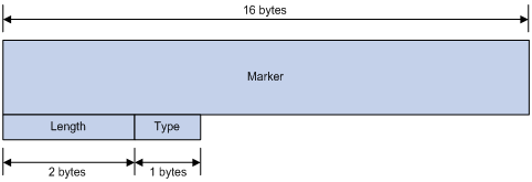
l Marker: The 16-byte field is used for BGP authentication. If no authentication information is available, the Marker must be all ones.
l Length: The 2-byte unsigned integer indicates the total length of the message.
l Type: This 1-byte unsigned integer indicates the type code of the message. The following type codes are defined: 1–Open, 2-Update, 3-Notification, 4–Keepalive, and 5–Route-refresh. The former four are defined in RFC1771, and the last one is defined in RFC2918.
Open
After a TCP connection is established, the first message sent by each side is an Open message for peer relationship establishment. An Open message contains the following fields:
Figure 1-2 BGP open message format
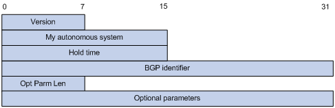
l Version: This 1-byte unsigned integer indicates the protocol version number. The current BGP version is 4.
l My autonomous system: This 2-byte unsigned integer indicates the Autonomous System number of the sender.
l Hold time: When establishing a peer relationship, two parties negotiate an identical hold time. If no Keepalive or Update is received from a peer within the hold time, the BGP connection is considered down.
l BGP identifier: An IP address that identifies the BGP router
l Opt Parm Len (Optional Parameters Length): Length of optional parameters, which is set to 0 if no optional parameter is available.
l Optional parameters: Used for BGP authentication, multiprotocol extensions, and so on.
Update
The Update messages are used to exchange routing information between peers. It can advertise a feasible route or remove multiple unfeasible routes. Its format is shown below:
Figure 1-3 BGP Update message format
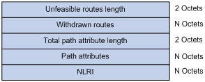
Each update message can advertise a group of feasible routes with identical attributes, and the routes are contained in the network layer reachable information (NLRI) field. The Path Attributes field carries attributes of these routes. Each update message can also carry multiple withdrawn routes in the Withdrawn Routes field.
l Unfeasible routes length: The total length of the Withdrawn Routes field in bytes. A value of 0 indicates no route is withdrawn from service, and the Withdrawn Routes field is not present in this Update message.
l Withdrawn routes: This is a variable length field that contains a list of withdrawn IP prefixes.
l Total path attribute length: Total length of the Path Attributes field in bytes. A value of 0 indicates that no Network Layer Reachability Information field is present in this Update message.
l Path attributes: List of path attributes related to NLRI. Each path attribute is a triple <attribute type, attribute length, attribute value> of variable length. BGP uses these attributes to avoid routing loops, and perform routing and protocol extensions.
l NLRI (Network Layer Reachability Information): Each feasible route is represented as <length, prefix>.
Notification
A Notification message is sent when an error is detected. The BGP connection is closed immediately after sending it. The Notification message format is shown below:
Figure 1-4 BGP Notification message format
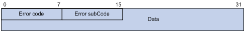
l Error code: Type of Notification.
l Error subcode: Specific information about the nature of the reported error.
l Data: Used to diagnose the reason for the Notification. The contents of the Data field depend upon the Error Code and Error Subcode. Erroneous part of data is recorded. The Data field length is variable.
Keepalive
Keepalive messages are sent between peers to maintain connectivity. Its format contains only the message header.
Route-refresh
A route-refresh message is sent to a peer to request the resending of the specified address family routing information. Its format is shown below:
Figure 1-5 BGP Route-refresh message format
![]()
l AFI: Address family identifier.
l Res: Reserved. Set to 0.
l SAFI: Subsequent Address Family Identifier.
BGP Path Attributes
Classification of path attributes
Path attributes fall into four categories:
l Well-known mandatory: Must be recognized by all BGP routers and must be included in every update message. Routing information errors occur without this attribute.
l Well-known discretionary: Can be recognized by all BGP routers and optional to be included in every update message as needed.
l Optional transitive: Transitive attribute between ASs. A BGP router not supporting this attribute can still receive routes with this attribute and advertise them to other peers.
l Optional non-transitive: If a BGP router does not support this attribute, it will not advertise routes with this attribute.
The usage of each BGP path attribute is described in the following table.
Table 1-1 Usage of BGP path attributes
|
Name |
Category |
|
ORIGIN |
Well-known mandatory |
|
AS_PATH |
Well-known mandatory |
|
NEXT_HOP |
Well-known mandatory |
|
LOCAL_PREF |
Well-known discretionary |
|
ATOMIC_AGGREGATE |
Well-known discretionary |
|
AGGREGATOR |
Optional transitive |
|
COMMUNITY |
Optional transitive |
|
MULTI_EXIT_DISC (MED) |
Optional non-transitive |
|
ORIGINATOR_ID |
Optional non-transitive |
|
CLUSTER_LIST |
Optional non-transitive |
Usage of BGP path attributes
1) ORIGIN
ORIGIN is a well-known mandatory attribute, which defines the origin of routing information, that is, how a route became a BGP route. It involves three types:
l IGP: Has the highest priority. Routes added to the BGP routing table using the network command have the IGP attribute.
l EGP: Has the second highest priority. Routes obtained via EGP have the EGP attribute.
l incomplete: Has the lowest priority. The source of routes with this attribute is unknown, which does not mean such routes are unreachable. The routes redistributed from other routing protocols have the incomplete attribute.
2) AS_PATH
AS_PATH is a well-known mandatory attribute. This attribute identifies the autonomous systems through which routing information carried in this Update message has passed. When a route is advertised from the local AS to another AS, each passed AS number is added into the AS_PATH attribute, thus the receiver can determine ASs to route the massage back. The number of the AS closest to the receiver’s AS is leftmost, as shown below:
Figure 1-6 AS_PATH attribute
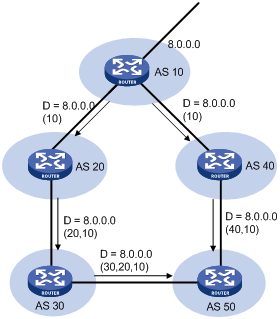
In general, a BGP router does not receive routes containing the local AS number to avoid routing loops.
![]()
The current implementation supports using the peer allow-as-loop command to receive routes containing the local AS number to meet special requirements.
The AS_PATH attribute can be used for route selection and filtering. BGP gives priority to the route with the shortest AS_PATH length if other factors are the same. As shown in the above figure, the BGP router in AS50 gives priority to the route passing AS40 for sending data to the destination 8.0.0.0.
In some applications, you can apply a routing policy to control BGP route selection by modifying the AS_PATH length.
By configuring an AS path filtering list, you can filter routes based on AS numbers contained in the AS_PATH attribute.
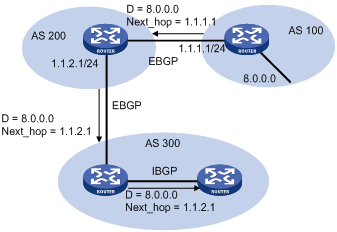
3) NEXT_HOP
Different from IGP, the NEXT_HOP attribute may not be the IP address of a directly connected router. It involves three types of values, as shown in Figure 1-7.
l When advertising a self-originated route to an eBGP peer, a BGP speaker sets the NEXT_HOP for the route to the address of its sending interface.
l When sending a received route to an eBGP peer, a BGP speaker sets the NEXT_HOP for the route to the address of the sending interface.
l When sending a route received from an eBGP peer to an iBGP peer, a BGP speaker does not modify the NEXT_HOP attribute. If load-balancing is configured, the NEXT_HOP attribute will be modified. For load-balancing information, refer to BGP Route Selection.
4) MED (MULTI_EXIT_DISC)
The MED attribute is exchanged between two neighboring ASs, each of which does not advertise the attribute to any other AS.
Similar with metrics used by IGP, MED is used to determine the best route for traffic going into an AS. When a BGP router obtains multiple routes to the same destination but with different next hops, it considers the route with the smallest MED value the best route if other conditions are the same. As shown below, traffic from AS10 to AS20 travels through Router B that is selected according to MED.
Figure 1-8 MED attribute
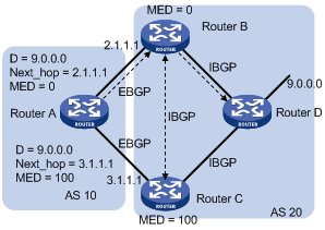
In general, BGP compares MEDs of routes received from the same AS only.
![]()
The current implementation supports using the compare-different-as-med command to force BGP to compare MED values of routes received from different ASs.
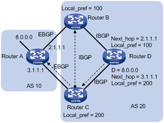
5) LOCAL_PREF
The LOCAL_PREF attribute is exchanged between iBGP peers only, and thus is not advertised to any other AS. It indicates the priority of a BGP router.
LOCAL_PREF is used to determine the best route for traffic leaving the local AS. When a BGP router obtains from several iBGP peers multiple routes to the same destination but with different next hops, it considers the route with the highest LOCAL_PREF value as the best route. As shown below, traffic from AS20 to AS10 travels through Router C that is selected according to LOCAL_PREF.
Figure 1-9 LOCAL_PREF attribute
6) COMMUNITY
The COMMUNITY attribute is used to simplify routing policy usage and ease management and maintenance. It identifies a collection of destination addresses having identical attributes, without physical boundaries in between, and having nothing to do with the local AS. Well known community attributes involve:
l Internet: By default, all routes belong to the Internet community. Routes with this attribute can be advertised to all BGP peers.
l No_Export: After received, routes with this attribute cannot be advertised out the local AS or out the local confederation but can be advertised to other sub-ASs in the confederation (for confederation information, refer to Settlements for Problems in Large Scale BGP Networks).
l No_Advertise: After received, routes with this attribute cannot be advertised to other BGP peers.
l No_Export_Subconfed: After received, routes with this attribute cannot be advertised out the local AS or other ASs in the local confederation.
BGP Route Selection
Route selection rules
The current BGP implementation supports the following route selection sequence:
l Discard routes with unreachable NEXT_HOPs first
l Select the route with the highest Preferred_value
l Select the route with the highest LOCAL_PREF
l Select the summary route
l Select the route with the shortest AS-PATH
l Select IGP, EGP, Incomplete routes in turn
l Select the route with the lowest MED value
l Select routes learned from eBGP, confederation, iBGP in turn
l Select the route with the smallest next hop cost
l Select the route with the shortest CLUSTER_LIST
l Select the route with the smallest ORIGINATOR_ID
l Select the route advertised by the router with the smallest Router ID
l Select the route with the lowest IP address
![]()
l CLUSTER_IDs of route reflectors form a CLUSTER_LIST. If a route reflector receives a route that contains its own CLUSTER ID in the CLUSTER_LIST, the router discards the route to avoid routing loops.
l If load balancing is configured, the system selects available routes to implement load balancing.
Route selection with BGP load balancing
The next hop of a BGP route may not be directly connected. One of the reasons is next hops in routing information exchanged between iBGPs are not modified. In this case, the BGP router needs to find the directly connected next hop via IGP. The matching route with the direct next hop is called the recursive route. The process of finding a recursive route is route recursion.
Currently, the system supports BGP load balancing based on route recursion, namely, if multiple recursive routes to the same destination are load balanced (suppose three direct next hop addresses), BGP generates the same number of next hops to forward packets. Note that BGP load balancing based on route recursion is always enabled by the system rather than configured using commands.
BGP differs from IGP in the implementation of load balancing in the following:
l IGP routing protocols such as RIP, OSPF compute metrics of routes, and then implement load balancing over routes with the same metric and to the same destination. The route selection criterion is metric.
l BGP has no route computation algorithm, so it cannot implement load balancing according to metrics of routes. However, BGP has abundant route selection rules, through which, it selects available routes for load balancing and adds load balancing to route selection rules.
![]()
l BGP implements load balancing only on routes that have the same AS_PATH, ORIGIN, LOCAL_PREF and MED.
l BGP load balancing is applicable between eBGP peers, between iBGP peers and between confederations.
l If multiple routes to the same destination are available, BGP selects a configurable number of routes for load balancing.
Figure 1-10 Network diagram for BGP load balancing
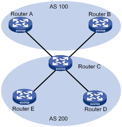
In the above figure, Router D and Router E are iBGP peers of Router C. Router A and Router B both advertise a route destined for the same destination to Router C. If load balancing is configured and the two routes have the same AS_PATH attribute, ORIGIN attribute, LOCAL_PREF and MED, Router C installs both the two routes to its route table for load balancing. After that, Router C forwards to Router D and Router E the route that has AS_PATH unchanged but has NEXT_HOP changed to Router C; other BGP transitive attributes are those of the best route.
BGP route advertisement rules
The current BGP implementation supports the following route advertisement rules:
l When multiple feasible routes to a destination exist, the BGP speaker advertises only the best route to its peers.
l A BGP speaker advertises only routes used by itself.
l A BGP speaker advertises routes learned through eBGP to all BGP peers, including both eBGP and iBGP peers.
l A BGP speaker does not advertise routes from an iBGP peer to other iBGP peers.
l A BGP speaker advertises routes learned through iBGP to eBGP peers. Note that if BGP and IGP synchronization is disabled, those routes are advertised to eBGP peers directly. If the feature is enabled, only after IGP advertises those routes, can BGP advertise the routes to eBGP peers.
l A BGP speaker advertises all routes to a newly connected peer.
iBGP and IGP Synchronization
Routing information synchronization between iBGP and IGP avoids giving wrong directions to routers outside of the local AS.
If a non-BGP router works in an AS, it may discard a packet due to an unreachable destination. As shown in Figure 1-11, Router E has learned a route of 8.0.0.0/8 from Router D via BGP. Then Router E sends a packet to 8.0.0.0/8 through Router D, which finds from its routing table that Router B is the next hop (configured using the peer next-hop-local command). Because Router D has learned the route to Router B via IGP, it forwards the packet to Router C through route recursion. Router C has no idea about the route 8.0.0.0/8, so it discards the packet.
Figure 1-11 iBGP and IGP synchronization
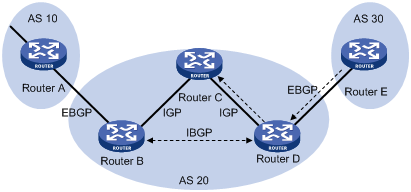
If synchronization is enabled in this example, only when the route 8.0.0.0/24 received from Router B is available in its IGP routing table, can Router D advertise the route to the eBGP peer.
You can disable the synchronization feature in the following cases:
l The local AS is not a transitive AS (AS20 is a transitive AS in the above figure).
l Routers in the local AS are iBGP fully meshed.
Settlements for Problems in Large Scale BGP Networks
Route summarization
Route summarization can reduce the routing table size on a large network, and allow BGP routers to advertise only summary routes rather than more specific routes.
Currently, the system supports both manual and automatic route summarization. Manual route summarization allows you to determine the attribute of a summary route and whether to advertise the route.
Route dampening
BGP route dampening is used to solve the issue of route instability such as route flaps, that is, a route comes up and disappears in the routing table frequently.
When a route flap occurs, the routing protocol sends an update to its neighbor, and then the neighbor needs to recalculate routes and modify the routing table. Therefore, frequent route flaps consume large bandwidth and CPU resources and even affect network normal operation.
In most cases, BGP is used in complex networks, where route changes are very frequent. To solve the problem caused by route flaps, BGP route dampening is used to suppress unstable routes.
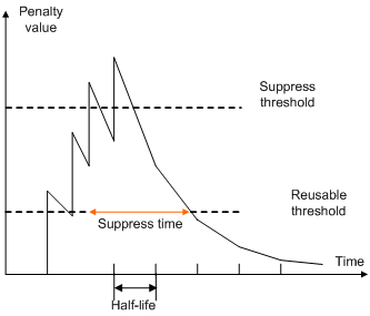
BGP route dampening uses a penalty value to judge the stability of a route. The bigger the value, the less stable the route. Each time a route flap occurs, BGP adds a penalty value (1000, which is a fixed number and cannot be changed) to the route. When the penalty value of the route exceeds the suppress value, the route is suppressed from being added into the routing table or being advertised to other BGP peers.
The penalty value of the suppressed route will decrease to a half of the suppress value after a period of time. This period is called Half-life. When the value decreases to the reusable threshold value, the route is added into the routing table and advertised to other BGP peers.
Figure 1-12 BGP route dampening
Peer group
You can organize BGP peers with the same attributes into a group to simplify configurations on them.
When a peer joins the peer group, the peer obtains the same configuration as the peer group. If the configuration of the peer group is changed, the configuration of group members is changed accordingly.
When a peer is added into a peer group, the peer enjoys the same route update policy as the peer group to improve route distribution efficiency.
![]()
If an option is configured for both a peer and its peer group, the last configuration takes effect.
Community
A peer group makes peers in it enjoy the same policy, while a community makes a group of BGP routers in several ASs enjoy the same policy. Community is a path attribute and advertised between BGP peers, without being limited by AS.
A BGP router can modify the community attribute for a route before sending it to other peers.
Besides using well-known community attributes, you can define extended community attributes by using a community list to define a routing policy.
Route reflector
iBGP peers should be fully meshed to maintain connectivity. If there are n routers in an AS, the number of iBGP connections is n (n-1)/2, and therefore large amounts of network and CPU resources will be consumed.
Using route reflectors can solve this issue. In an AS, a router acts as a route reflector, and other routers act as clients connecting to the route reflector. The route reflector forwards routing information between clients, and thus BGP sessions between clients need not be established.
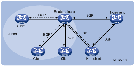
A router that is neither a route reflector nor a client is a non-client, which has to establish BGP sessions to the route reflector and other non-clients, as shown below.
Figure 1-13 Network diagram for route reflector
The route reflector and clients form a cluster. In some cases, you can configure more than one route reflector in a cluster to improve network reliability and prevent single point failure, as shown in the following figure. The configured route reflectors must have the same Cluster_ID to avoid routing loops.
Figure 1-14 Network diagram for route reflectors
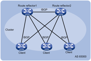
When the BGP routers in an AS are fully meshed, route reflection is unnecessary because it consumes more bandwidth resources. You can use related commands to disable route reflection in this case.
![]()
After route reflection is disabled between clients, routes can still be reflected between a client and a non-client.
Confederation
Confederation is another method to deal with growing iBGP connections in ASs. It splits an AS into multiple sub-ASs. In each sub-AS, iBGP peers are fully meshed, and eBGP connections are established between sub-ASs, as shown below:
Figure 1-15 Confederation network diagram
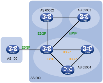
From the perspective of a non-confederation BGP speaker, it needs not know sub-ASs in the confederation. The ID of the confederation is the number of the AS. In the above figure, AS 200 is the confederation ID.
The deficiency of confederation is: when changing an AS into a confederation, you need to reconfigure your routers, and the topology will be changed.
In large-scale BGP networks, both route reflector and confederation can be used.
BGP GR
![]()
For GR (Graceful Restart) information, refer to GR Configuration in the System Volume.
1) To establish a BGP session with a peer, a BGP GR Restarter sends an OPEN message with GR capability to the peer.
2) Upon receipt of this message, the peer is aware that the sending router is capable of Graceful Restart, and sends an OPEN message with GR Capability to the GR Restarter to establish a GR session. If neither party has the GR capability, the session established between them will not be GR capable.
3) The GR session between the GR Restarter and its peer goes down when the GR Restarter restarts BGP. The GR capable peer will mark all routes associated with the GR Restarter as stale. However, during the configured GR Time, it still uses these routes for packet forwarding.
4) After the restart, the GR Restarter will reestablish a GR session with its peer and send a new GR message notifying the completion of restart. Routing information is exchanged between them for the GR Restarter to create a new routing table and forwarding table with stale routing information removed. Then the BGP routing convergence is complete.
MP-BGP
Overview
BGP-4 supports IPv4, but does not support other network layer protocols like IPv6.
To support more network layer protocols, IETF extended BGP-4 by introducing Multiprotocol Extensions for BGP-4 (MP-BGP) in RFC2858.
Routers supporting MP-BGP can communicate with routers not supporting MP-BGP.
MP-BGP extended attibutes
In BGP-4, the three types of attributes for IPv4, namely NLRI, NEXT_HOP and AGGREGATOR (AGGREGATOR contains the IP address of the speaker generating the summary route) are all carried in updates.
To support multiple network layer protocols, BGP-4 puts information about network layer into NLRI and NEXT_HOP. MP-BGP introduced two path attributes:
l MP_REACH_NLRI: Multiprotocol Reachable NLRI, for advertising feasible routes and next hops
l MP_UNREACH_NLRI: Multiprotocol Unreachable NLRI, for withdrawing unfeasible routes
The above two attributes are both optional non-transitive, so BGP speakers not supporting multi-protocol ignore the two attributes and do not forward them to its peers.
Address family
MP-BGP uses address families to differentiate network layer protocols. For address family values, refer to RFC 1700 (Assigned Numbers). Currently, the system supports multiple MP-BGP extensions, including VPN extension and IPv6 extension. Different extensions are configured in respective address family view.
![]()
l For information about the VPN extension application, refer to MPLS L3VPN Configuration in the MPLS Volume.
l For information about the IPv6 extension application, refer to IPv6 BGP Configuration in the IP Routing Volume.
l This chapter gives no detailed commands related to any specific extension application in MP-BGP address family view.
Protocols and Standards
l RFC1771: A Border Gateway Protocol 4 (BGP-4)
l RFC2858: Multiprotocol Extensions for BGP-4
l RFC3392: Capabilities Advertisement with BGP-4
l RFC2918: Route Refresh Capability for BGP-4
l RFC2439: BGP Route Flap Damping
l RFC1997: BGP Communities Attribute
l RFC2796: BGP Route Reflection
l RFC3065: Autonomous System Confederations for BGP
l draft-ietf-idr-restart-08: Graceful Restart Mechanism for BGP
BGP Configuration Task List
Complete the following tasks to configure BGP:
|
Task |
Remarks |
|
|
Required |
||
|
Optional |
||
|
Allowing Establishment of eBGP Connection to a Non Directly Connected Peer/Peer Group |
Optional |
|
|
Required to choose either. |
||
|
Optional |
||
|
Optional |
||
|
Configuring BGP Route Distribution/Reception Filtering Policies |
||
|
Optional |
||
|
Optional |
||
|
Optional |
||
|
Optional |
||
|
Optional |
||
|
Optional |
||
|
Optional |
||
|
Optional |
||
|
Optional |
||
|
Optional |
||
|
Optional |
||
|
Optional |
||
|
Optional |
||
|
Optional |
||
|
Optional |
||
|
Optional |
||
|
Optional |
||
|
Optional |
||
|
Optional |
||
|
Optional |
||
Configuring BGP Basic Functions
![]()
This section does not differentiate between BGP and MP-BGP.
Prerequisites
The neighboring nodes are accessible to each other at the network layer.
Creating a BGP Connection
A router ID is the unique identifier of a BGP router in an AS.
l To ensure the uniqueness of a router ID and enhance network reliability, you can specify in BGP view the IP address of a local loopback interface as the router ID.
l If no router ID is specified in BGP view, the global router ID is used. For information about global router ID, refer to IP Routing Overview in the IP Routing Volume.
l If the global router ID is used and then it is removed, the system will select a new router ID.
l If the router ID is specified in BGP view, using the undo router-id command can make the system select a new router ID.
Follow these steps to create a BGP connection:
|
To do… |
Use the command… |
Remarks |
|
Enter system view |
system-view |
— |
|
Enable BGP and enter BGP view |
bgp as-number |
— Not enabled by default |
|
Specify a Router ID |
router-id router-id |
Optional By default, the global router ID is used. |
|
Specify a peer or a peer group and its AS number |
peer { group-name | ip-address } as-number as-number |
Required Not specified by default |
|
Enable the default use of IPv4 unicast address family for the peers that are established using the peer as-number command |
default ipv4-unicast |
Optional Enabled by default |
|
Enable a peer |
Optional Enabled by default |
|
|
Configure a description for a peer/peer group |
peer { group-name | ip-address } description description-text |
Not configured by default. |
l Since a router can reside in only one AS, the router can run only one BGP process.
l You need to create a peer group before configuring it.
Specifying the Source Interface for TCP Connections
BGP uses TCP as the transport layer protocol. By default, BGP uses the output interface of the optimal router to a peer as the source interface for establishing TCP connections to the peer. If a BGP router has multiple links to a peer, when the source interface fails, BGP has to reestablish TCP connections, causing network oscillation. Therefore, it is recommended to use a loopback interface as the source interface to enhance stability of BGP connections.
Follow these steps to specify the source interface of TCP connections:
|
To do… |
Use the command… |
Remarks |
|
Enter system view |
system-view |
— |
|
Enter BGP view |
bgp as-number |
— |
|
Specify the source interface for establishing TCP connections to a peer or peer group |
peer { group-name | ip-address } connect-interface interface-type interface-number |
Required By default, BGP uses the outbound interface of the best route to the BGP peer/peer group as the source interface for establishing a TCP connection to the peer/peer group. |
![]()
To establish multiple BGP connections between two routers, you need to specify on the local router the source interface for establishing TCP connections to each peer; otherwise, the local BGP router may fail to establish TCP connections to a peer when using the outbound interface of the best route to the peer as the source interface.
Allowing Establishment of eBGP Connection to a Non Directly Connected Peer/Peer Group
In general, direct physical links should be available between eBGP peers. If not, you can use the peer ebgp-max-hop command to establish a TCP connection over multiple hops between two peers.
Follow these steps to allow establishment of eBGP connection to a non directly connected peer/peer group:
|
To do… |
Use the command… |
Remarks |
|
Enter system view |
system-view |
— |
|
Enter BGP view |
bgp as-number |
— |
|
Allow the establishment of eBGP connection to a non directly connected peer/peer group |
peer { group-name | ip-address } ebgp-max-hop [ hop-count ] |
Optional Not allowed by default. |
![]()
The peer ebgp-max-hop command needs not be configured if the two eBGP peers are directly connected.
Controlling Route Generation
Different from IGP, BGP focuses on route generation and advertisement control and optimal route selection.
There are to ways to generate BGP routes:
l Configure BGP to advertise local networks
l Configure BGP to redistribute routes from other routing protocols, including the default route
Prerequisites
BGP connections have been created.
Injecting a Local Network
In BGP view, you can inject a local network to allow BGP to advertise it to BGP peers. The origin attribute of routes advertised in this way is IGP. You can also reference a route policy to flexibly control route advertisement. The network to be injected must be available in the local IP routing table.
Follow these steps to inject a local network:
|
To do… |
Use the command… |
Remarks |
|
Enter system view |
system-view |
— |
|
Enter BGP view |
bgp as-number |
— |
|
Inject a network to the BGP routing table |
network ip-address [ mask | mask-length ] route-policy route-policy-name |
Optional Not injected by default |
Configuring BGP Route Redistribution
BGP does not find routes by itself. Rather, it redistributes routing information in the local AS from other routing protocols. During route redistribution, you can configure BGP to filter routing information from specific routing protocols.
The origin attribute of routes redistributed using the import-route command is Incomplete.
Follow these steps to configure BGP route redistribution:
|
To do… |
Use the command… |
Remarks |
|
Enter system view |
system-view |
— |
|
Enter BGP view |
bgp as-number |
— |
|
Enable route redistribution from a routing protocol into BGP |
import-route protocol [ process-id | all-processes ] [ med med-value | route-policy route-policy-name ] * |
Required Not enabled by default |
Enabling Default Route Redistribution into BGP
Using the import-route command cannot redistribute a default route. To do so, complete the following configuration.
Follow these steps to enable default route redistribution into BGP:
|
To do… |
Use the command… |
Remarks |
|
Enter system view |
system-view |
— |
|
Enter BGP view |
bgp as-number |
— |
|
Enable route redistribution from a routing protocol into BGP |
import-route protocol [ process-id | all-processes ] [ med med-value | route-policy route-policy-name ] * |
Required Not redistributed by default |
|
Enable default route redistribution into BGP |
default-route imported |
Optional Not enabled by default |
Controlling Route Distribution and Reception
Prerequisites
BGP connections have been created.
Configuring BGP Route Summarization
To reduce the routing table size on medium and large BGP networks, you need to configure route summarization on BGP routers. BGP supports two summarization modes: automatic and manual. Manual summary routes enjoy a higher priority than automatic ones.
Configure automatic route summarization
After automatic route summarization is configured, BGP summarizes redistributed IGP subnets to advertise only natural networks. Routes injected with the network command can not be summarized.
Follow these steps to configure automatic route summarization:
|
To do… |
Use the command… |
Remarks |
|
Enter system view |
system-view |
— |
|
Enter BGP view |
bgp as-number |
— |
|
Configure automatic route summarization |
summary automatic |
Required Not configured by default. |
Configure manual route summarization
By configuring manual route summarization, you can summarize both redistributed routes and routes injected using the network command and determine the mask length for a summary route as needed.
Follow these steps to configure BGP manual route summarization:
|
To do… |
Use the command… |
Remarks |
|
Enter system view |
system-view |
— |
|
Enter BGP view |
bgp as-number |
— |
|
Configure manual route summarization |
aggregate ip-address { mask | mask-length } [ as-set | attribute-policy route-policy-name | detail-suppressed | origin-policy route-policy-name | suppress-policy route-policy-name ]* |
Required Not configured by default. |
Advertising a Default Route to a Peer or Peer Group
After this task is configured, the BGP router sends a default route with the next hop being itself to the specified peer/peer group, regardless of whether the default route is available in the routing table.
Follow these steps to advertise a default route to a peer or peer group:
|
To do… |
Use the command… |
Remarks |
|
Enter system view |
system-view |
— |
|
Enter BGP view |
bgp as-number |
— |
|
Advertise a default route to a peer or peer group |
peer { group-name | ip-address } default-route-advertise [ route-policy route-policy-name ] |
Required Not advertised by default |
Configuring BGP Route Distribution/Reception Filtering Policies
Prerequisites
You need to configure following filters as needed.
l ACL
l IP prefix list
l Route policy
l AS-path ACL
For how to configure an ACL, refer to ACL Configuration in the Security Volume.
For how to configure an IP prefix list, route policy and AS-path ACL, refer to Route Policy Configuration in the Routing Volume.
Configure BGP route distribution filtering policies
Follow these steps to configure BGP route distribution filtering policies:
|
To do… |
Use the command… |
Remarks |
|
Enter system view |
system-view |
— |
|
Enter BGP view |
bgp as-number |
— |
|
Configure the filtering of redistributed routes |
filter-policy { acl-number | ip-prefix ip-prefix-name } export [ direct | isis process-id | ospf process-id | rip process-id | static ] |
Required to choose any; Not configured by default.; You can configure a filtering policy as needed; If several filtering policies are configured, they are applied in the following sequence: l filter-policy export l peer filter-policy export l peer as-path-acl export l peer ip-prefix export l peer route-policy export Only routes pass the first policy, can they go to the next, and only routes passing all the configured policies, can they be advertised. |
|
Reference a routing policy to filter advertisements to a peer/peer group |
peer { group-name | ip-address } route-policy route-policy-name export |
|
|
Reference an ACL to filer advertisements to a peer/peer group |
peer { group-name | ip-address } filter-policy acl-number export |
|
|
Reference an AS path ACL to filter routing information sent to a peer/peer group |
peer { group-name | ip-address } as-path-acl as-path-acl-number export |
|
|
Reference an IP prefix list to filer routing information sent to a peer/peer group |
peer { group-name | ip-address } ip-prefix ip-prefix-name export |
Configure BGP route reception filtering policies
Only routes permitted by the configured filtering policies can be installed into the local BGP routing table. Members of a peer group can have different route reception filtering policies from the peer group.
Follow these steps to configure BGP route reception filtering policies:
|
To do… |
Use the command… |
Remarks |
|
Enter system view |
system-view |
— |
|
Enter BGP view |
bgp as-number |
— |
|
Filter incoming routes with an ACL or IP prefix list |
filter-policy { acl-number | ip-prefix ip-prefix-name } import |
Required to choose any; No route reception filtering is configured by default; You can configure a filtering policy as needed; If several filtering policies are configured, they are applied in the following sequence: l filter-policy import l peer filter-policy import l peer as-path-acl import l peer ip-prefix import l peer route-policy import Only routes passing the first policy, can they go to the next, and only routes passing all the configured policies, can they be received. |
|
Reference a routing policy to filter routes from a peer/peer group |
peer { group-name | ip-address } route-policy route-policy-name import |
|
|
Reference an ACL to filter routing information from a peer/peer group |
peer { group-name | ip-address } filter-policy acl-number import |
|
|
Reference an AS path ACL to filter routing information from a peer/peer group |
peer { group-name | ip-address } as-path-acl as-path-acl-number import |
|
|
Reference an IP prefix list to filter routing information from a peer/peer group |
peer { group-name | ip-address } ip-prefix ip-prefix-name import |
Enabling BGP and IGP Route Synchronization
By default, when a BGP router receives an iBGP route, it only checks the reachability of the route’s next hop before advertisement. With BGP and IGP synchronization enabled, the BGP router cannot advertise the iBGP route to eBGP peers unless the route is also available in the IGP routing table.
Follow these steps to enable BGP and IGP synchronization:
|
To do… |
Use the command… |
Remarks |
|
Enter system view |
system-view |
— |
|
Enter BGP view |
bgp as-number |
— |
|
Enable synchronization between BGP and IGP |
synchronization |
Required Not enabled by default |
Limiting Prefixes Received from a Peer/Peer Group
Follow these steps to configure the maximum number of prefixes allowed to be received from a peer/peer group:
|
To do… |
Use the command… |
Remarks |
|
Enter system view |
system-view |
— |
|
Enter BGP view |
bgp as-number |
— |
|
Specify the maximum number of prefixes that can be received from a peer/peer group. If the number is reached, the router breaks down the BGP connection to the peer. |
peer { group-name | ip-address } route-limit prefix-number [ percentage-value ] |
Required to choose any; No limit is configured by default. |
|
Specify the maximum number of prefixes that can be received from a peer/peer group. If the number is reached, the router outputs alert information but does not break down the BGP connection to the peer. |
peer { group-name | ip-address } route-limit prefix-number alert-only [ percentage-value ] |
|
|
Specify the maximum number of prefixes that can be received from a peer/peer group. If the number is reached, the router breaks down the BGP connection to the peer and then reestablishes a BGP connection to the peer. |
peer { group-name | ip-address } route-limit prefix-number reconnect reconnect-time [ percentage-value ] |
Configuring BGP Route Dampening
By configuring BGP route dampening, you can suppress unstable routes from being added to the local routing table or being advertised to BGP peers.
Follow these steps to configure BGP route dampening:
|
To do… |
Use the command… |
Remarks |
|
Enter system view |
system-view |
— |
|
Enter BGP view |
bgp as-number |
— |
|
Configure BGP route dampening |
dampening [ half-life-reachable half-life-unreachable reuse suppress ceiling | route-policy route-policy-name ] * |
Required Not configured by default. |
Configuring a Shortcut Route
An eBGP route received has a priority of 255, lower than a local route. This task allows you configure an eBGP route as a shortcut route that has the same priority as a local route and thus has greater likehood to become the optimal route.
Follow these steps to configure a shortcut route:
|
To do… |
Use the command… |
Remarks |
|
Enter system view |
system-view |
— |
|
Enter BGP view |
bgp as-number |
— |
|
Configure a shortcut route |
network ip-address [ mask | mask-length ] short-cut |
Optional By default, an eBGP route received has a priority of 255. |
Configuring BGP Route Attributes
Prerequisites
BGP connections have been created.
Specifying a Preferred Value for Routes Received
By default, routes received from a peer have a preferred value of 0. Among multiple routes that have the same destination/mask and are learned from different peers, the one with the greatest preferred value is selected as the route to the destination.
Follow these steps to specify a preferred value for routes from a peer or peer group:
|
To do… |
Use the command… |
Remarks |
|
Enter system view |
system-view |
— |
|
Enter BGP view |
bgp as-number |
— |
|
Specify a preferred value for routes received from a peer or peer group |
peer { group-name | ip-address } preferred-value value |
Optional The preferred value is 0 by default. |
Configuring Preferences for BGP Routes
A router may run multiple routing protocols, each of which has a preference specified. If they find the same route, the route found by the routing protocol with the highest preference is selected.
This task allows you configure preferences for external, internal, local BGP routes and reference a route policy to set preferences for matching routes as needed.
Follow these steps to configure preferences for BGP routes:
|
To do… |
Use the command… |
Remarks |
|
Enter system view |
system-view |
— |
|
Enter BGP view |
bgp as-number |
— |
|
Configure preferences for external, internal, local BGP routes |
preference { external-preference internal-preference local-preference | route-policy route-policy-name } |
Optional The default preferences of external, internal, and local BGP routes are 255, 255, and 130 respectively. |
Configure the Default Local Preference
The local preference is used to determine the best route for traffic leaving the local AS. When a BGP router obtains from several iBGP peers multiple routes to the same destination but with different next hops, it considers the route with the highest local preference as the best route.
This task allows you to specify the default local preference for routes sent to iBGP peers.
Follow these steps to specify the default local preference:
|
To do… |
Use the command… |
Remarks |
|
Enter system view |
system-view |
— |
|
Enter BGP view |
bgp as-number |
— |
|
Configure the default local preference |
default local-preference value |
Optional 100 by default |
Configuring the MED Attribute
MED is used to determine the best route for traffic going into an AS. When a BGP router obtains from eBGP peers multiple routes to the same destination but with different next hops, it considers the route with the smallest MED value as the best route if other conditions are the same.
Configure the default MED value
Follow these steps to configure the default MED value:
|
To do… |
Use the command… |
Remarks |
|
Enter system view |
system-view |
— |
|
Enter BGP view |
bgp as-number |
— |
|
Configure the default MED value |
default med med-value |
Optional 0 by default |
Enable the comparison of MED of routes from different ASs
Follow these steps to enable the comparison of MED of routes from different ASs:
|
To do… |
Use the command… |
Remarks |
|
Enter system view |
system-view |
— |
|
Enter BGP view |
bgp as-number |
— |
|
Enable the comparison of MED of routes from different ASs |
compare-different-as-med |
Required Not enabled by default |
Enable the comparison of MED of routes from each AS
Route learning sequence may affect optimal route selection.
Figure 1-16 Route selection based on MED
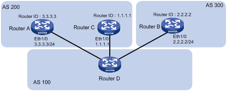
As shown in the figure above, Router D learns network 10.0.0.0 from both Router A and Router B. Because Router B has a smaller router ID, the route learned from it is optimal.
Network NextHop MED LocPrf PrefVal Path/Ogn
*>i 10.0.0.0 2.2.2.2 50 0 300e
* i 3.3.3.3 50 0 200e
When Router D learns network 10.0.0.0 from Router C which has a smaller router ID than Router B, the route from Router C becomes optimal, as shown below.
Network NextHop MED LocPrf PrefVal Path/Ogn
*>i 10.0.0.0 1.1.1.1 60 0 200e
* i 10.0.0.0 2.2.2.2 50 0 300e
* i 3.3.3.3 50 0 200e
However, Router C and Router B reside in the same AS, and therefore BGP will compare the MEDs of them. Since Router C has a greater MED, network 10.0.0.0 learned from it is not optimal.
In this case, you can configure the bestroute compare-med command on Router D. After that, Router D will put routes received from the same AS into a group. For the same group, the route with the lowest MED is selected. Then, it compares routes from different groups. This mechanism avoids the above-mentioned problem. The following output is the BGP routing table on Router D after the comparison of MED of routes from each AS is enabled. Network 10.0.0.0 learned from Router C is the optimal route.
Network NextHop MED LocPrf PrefVal Path/Ogn
*>i 10.0.0.0 3.3.3.3 50 0 200e
* i 10.0.0.0 2.2.2.2 50 0 300e
* i 1.1.1.1 60 0 200e
Note that, in this case, BGP load balancing cannot be implemented because load balanced routes must have the same AS-path attribute.
Follow these steps to enable the comparison of MED of routes from each AS:
|
To do… |
Use the command… |
Remarks |
|
Enter system view |
system-view |
— |
|
Enter BGP view |
bgp as-number |
— |
|
Enable the comparison of MED of routes from each AS |
bestroute compare-med |
Optional Not enabled by default |
Enable the comparison of MED of routes from confederation peers
Follow these steps to enable the comparison of MED of routes from confederation peers:
|
To do… |
Use the command… |
Remarks |
|
Enter system view |
system-view |
— |
|
Enter BGP view |
bgp as-number |
— |
|
Enable the comparison of MED of routes from confederation peers |
bestroute med-confederation |
Optional Not enabled by default |
![]()
The MED attributes of routes from confederation peers are not compared if their AS-path attributes contain AS numbers that don’t belong to the confederation. For example, there are three routes: AS-path attributes of them are 65006 65009, 65007 65009 and 65008 65009, and MED values of them are 2, 3, and 1. Because the third route contains an AS number that does not belong to the confederation, the first route becomes the optimal route.
Configuring the Next Hop Attribute
By default, when advertising routes to an iBGP peer/peer group, a BGP router does not set itself as the next hop. However, to ensure a BGP peer can find the correct next hop in some cases, you need to configure the router as the next hop for routes sent to the peer.
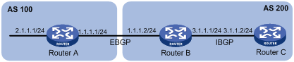
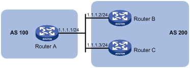
For example, as shown in the figure below, Router A and Router B establish an eBGP neighbor relationship, and Router B and Router C establish an iBGP neighbor relationship. When Router B advertises a network learned from Router A to Router C, if Router C has no route to IP address 1.1.1.1/24, you need to configure Router B to set itself as the next hop (3.1.1.1/24) for the route to be sent to Router C.
Figure 1-17 Next hop attribute configuration
If a BGP router has two peers on a common broadcast network, it does not set itself as the next hop for routes sent to an eBGP peer by default. As shown below, Router A and Router B establish an eBGP neighbor relationship, and Router B and Router C establish an iBGP neighbor relationship. They are on the same broadcast network 1.1.1.0/24. When Router B sends eBGP routes to Router A, it does not set itself as the next hop by default. However, you can configure Router B to set it as the nexthop (1.1.1.2/24) for routes sent to Router A by using the peer next-hop-local command as needed.
Figure 1-18 Next hop attribute configuration
Note that: if you have configured BGP load balancing on a BGP router, the router will set it as the next hop for routes sent to an iBGP peer/peer group regardless of whether the peer next-hop-local command is configured.
Follow these steps to configure the next hop attribute:
|
To do… |
Use the command… |
Remarks |
|
Enter system view |
system-view |
— |
|
Enter BGP view |
bgp as-number |
— |
|
Specify the router as the next hop of routes sent to a peer/peer group |
peer { group-name | ip-address } next-hop-local |
Optional By default, the router sets it as the next hop for routes sent to an eBGP peer/peer group, but does not set it as the next hop for routes sent to an iBGP peer/peer group. |
Configuring the AS-PATH Attribute
Permit local AS number to appear in routes from a peer/peer group
In general, BGP checks whether the AS_PATH attribute of a route from a peer contains the local AS number. If so, it discards the route to avoid routing loops.
This task allows you to permit local AS number to appear in routes from a peer/peer group and specify the appearance times.
|
To do… |
Use the command… |
Remarks |
|
Enter system view |
system-view |
— |
|
Enter BGP view |
bgp as-number |
— |
|
Permit local AS number to appear in routes from a peer/peer group and specify the appearance times |
peer { group-name | ip-address } allow-as-loop [ number ] |
Optional By default, the local AS number is not allowed. |
Disable BGP from considering AS_PATH during best route selection
Follow these steps to disable BGP from considering AS_PATH during best route selection:
|
To do… |
Use the command… |
Remarks |
|
Enter system view |
system-view |
— |
|
Enter BGP view |
bgp as-number |
— |
|
Disable BGP from considering AS_PATH during best route selection |
bestroute as-path-neglect |
Optional By default, BGP considers AS_PATH during best route selection. |
Specify a fake AS number for a peer/peer group
When Router A in AS 2 is moved to AS 3, you can configure Router A to specify a fake AS number of 2 for created connections to eBGP peers/peer groups. In this way, these eBGP peers still think Router A is in AS 2 and thus need not change their configurations. This feature ensures uninterrupted BGP services.
Follow these steps to specify a fake AS number for a peer/peer group:
|
To do… |
Use the command… |
Remarks |
|
Enter system view |
system-view |
— |
|
Enter BGP view |
bgp as-number |
— |
|
Specify a fake AS number for a peer/peer group |
peer { group-name | ip-address } fake-as as-number |
Optional Not specified by default |
![]()
This command is only applicable to an eBGP peer or peer group.
Configure AS number substitution
In MPLS L3VPN, if eBGP is used between PE and CE, sites in different geographical areas should have different AS numbers assigned to ensure correct route advertisement. If different CEs use the same AS number, you need to configure the corresponding PE to replace the AS number of the CE as its own AS number. This feature is used for route advertisement only.
Figure 1-19 AS number substitution configuration
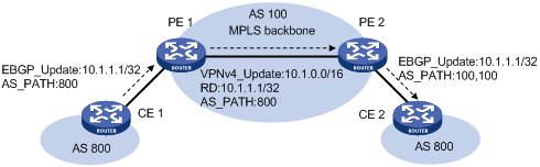
As shown in the above figure, CE 1 and CE 2 use the same AS number of 800. If AS number substitution for CE 2 is configured on PE 2, when PE 2 receives a BGP update sent from CE 1, it replaces AS number 800 as its own AS number 100. Similar configuration should also be made on PE 1.
Follow these steps to configure AS number substitution for a peer/peer group:
|
To do… |
Use the command… |
Remarks |
|
Enter system view |
system-view |
— |
|
Enter BGP view |
bgp as-number |
— |
|
Replace the AS number of a peer/peer group in the AS_PATH attribute as the local AS number |
peer { group-name | ip-address } substitute-as |
Optional Not configured by default. |
![]()
Improper AS number substitution configuration may cause route loops; use this command with caution.
Remove private AS numbers from updates to a peer/peer group
Follow these steps to remove private AS numbers from updates to a peer/peer group:
|
To do… |
Use the command… |
Remarks |
|
Enter system view |
system-view |
— |
|
Enter BGP view |
bgp as-number |
— |
|
Configure BGP to remove private AS numbers from the AS_PATH attribute of updates to a peer/peer group |
peer { group-name | ip-address } public-as-only |
Optional By default, BGP updates carry private AS numbers. |
Tuning and Optimizing BGP Networks
Prerequisites
BGP connections have been created.
Configuring BGP Keepalive Interval and Holdtime
After establishing a BGP connection, two routers send keepalive messages periodically to each other to keep the connection. If a router receives no keepalive or update message from the peer within the holdtime, it tears down the connection.
If two parties have the same timer assigned with different values, the smaller one is used by the two parties.
Follow these steps to configure BGP keepalive interval and holdtime:
|
To do… |
Use the command… |
Remarks |
|
Enter system view |
system-view |
— |
|
Enter BGP view |
bgp as-number |
— |
|
Configure the global keepalive interval and holdtime |
timer keepalive keepalive hold holdtime |
Optional By default, the keepalive interval is 60 seconds, and holdtime is 180 seconds. |
|
Configure the keepalive interval and holdtime for a peer/peer group |
peer { group-name | ip-address } timer keepalive keepalive hold holdtime |
![]()
l The maximum keepalive interval should be one third of the holdtime and no less than 1 second. The holdtime is no less than 3 seconds unless it is set to 0.
l The intervals set with the peer timer command are preferred to those set with the timer command.
l If the router has established a neighbor relationship with a peer, you need to reset the BGP connection to validate the new set timers.
Configuring the Interval for Sending the Same Update
Follow these steps to configure the interval for sending the same update to a peer/peer group:
|
To do… |
Use the command… |
Remarks |
|
Enter system view |
system-view |
— |
|
Enter BGP view |
bgp as-number |
— |
|
Configure the interval for sending the same update to a peer/peer group |
peer { group-name | ip-address } route-update-interval interval |
Optional The intervals for sending the same update to an iBGP peer and an eBGP peer default to 15 seconds and 30 seconds respectively. |
Configuring BGP Soft-Reset
After modifying a route selection policy, you have to reset BGP connections to make the new one take effect, causing short time disconnection.
The current BGP implementation supports the route-refresh capability, with which, a router can dynamically refresh its BGP routing table when the route selection policy is modified, without tearing down BGP connections. If a BGP peer does not support route-refresh, you need to save updates from the peer on the local router. After that, when a route selection policy is modified, the router can refresh its BGP routing table by using such updates without tearing down BGP connections.
Configure automatic soft-reset
After route refresh is enabled for peers and then a policy is modified, the router advertises a route-refresh message to the peers, which then resend their routing information to the router. In this way, the router can perform dynamic route update and apply the new policy without tearing down BGP connections.
Follow these steps to enable BGP route refresh for a peer/peer group:
|
To do… |
Use the command… |
Remarks |
|
Enter system view |
system-view |
— |
|
Enter BGP view |
bgp as-number |
— |
|
Enable BGP route refresh for a peer/peer group |
peer { group-name | ip-address } capability-advertise route-refresh |
Optional Enabled by default |
Configure manual soft-reset
If a BGP peer does not support route-refresh, you need to save updates from the peer on the local router by using the peer keep-all-routes command. When a route selection policy is modified, you can use the refresh bgp command to refresh the BGP routing table by applying the new policy.
Following these steps to save all route updates from a peer/peer group:
|
To do… |
Use the command… |
Remarks |
|
Enter system view |
system-view |
— |
|
Enter BGP view |
bgp as-number |
— |
|
Disable BGP route-refresh and multi-protocol extension capability for a peer/peer group |
peer { group-name | ip-address } capability-advertise conventional |
Optional Enabled by default |
|
Save all routes from a peer/peer group |
peer { group-name | ip-address } keep-all-routes |
Optional Not saved by default |
|
Return to user view |
return |
— |
|
Perform manual soft reset on BGP connections |
refresh bgp { all | ip-address | group group-name | external | internal } { export | import } |
Required |
Enabling Quick eBGP Session Reestablishment
If the router receives no keepalive messages from a BGP peer within the holdtime, it tears down the connection to the peer.
With quick eBGP connection reestablishment enabled, the router, when the link to a directly connected eBGP peer is down, will reestablish a session to the eBGP peer immediately.
Follow these steps to enable quick eBGP session reestablishment:
|
To do… |
Use the command… |
Remarks |
|
Enter system view |
system-view |
— |
|
Enter BGP view |
bgp as-number |
— |
|
Enable quick eBGP session reestablishment |
ebgp-interface-sensitive |
Optional Not enabled by default |
Enabling MD5 Authentication for TCP Connections
BGP employs TCP as the transport protocol. To enhance security, you can configure BGP to perform MD5 authentication when establishing a TCP connection. The two parties must have the same password configured to establish TCP connections. BGP MD5 authentication is not for BGP packets, but for TCP connections. If the authentication fails, no TCP connection can be established.
Follow these steps to enable MD5 authentication for TCP connections:
|
To do… |
Use the command… |
Remarks |
|
Enter system view |
system-view |
— |
|
Enter BGP view |
bgp as-number |
— |
|
Enable MD5 authentication when establishing a TCP connection to the peer/peer group |
peer { group-name | ip-address } password { cipher | simple } password |
Optional Not enabled by default |
Configuring BGP Load Balancing
If multiple paths to a destination exist, you can configure load balancing over such paths to improve link utilization.
Follow these steps to configure BGP load balancing:
|
To do… |
Use the command… |
Remarks |
|
Enter system view |
system-view |
— |
|
Enter BGP view |
bgp as-number |
— |
|
Configure the maximum number of BGP routes for load balancing |
balance number |
Optional Load balancing is not enabled by default. |
Forbiding Session Establishment with a Peer or Peer Group
Follow these steps to forbid session establishment with a peer or peer group:
|
To do… |
Use the command… |
Remarks |
|
Enter system view |
system-view |
— |
|
Enter BGP view |
bgp as-number |
— |
|
Forbid session establishment with a peer or peer group |
peer { group-name | ip-address } ignore |
Optional Not forbidden by default |
Configuring a Large Scale BGP Network
In a large-scale BGP network, configuration and maintenance become difficult due to large numbers of BGP peers. To facilitate configuraiton in this case, you can configure peer group, community, route reflector or confederation as needed.
Configuration Prerequisites
Peering nodes are accessible to each other at the network layer.
Configuring BGP Peer Groups
A peer group is a group of peers with the same route selection policy.
In a large scale network, many peers may use the same route selection policy. You can configure a peer group and add these peers into this group. In this way, peers can share the same policy as the peer group. When the policy of the group is modified, the modification also applies to peers in it, thus simplifying configuration.
A peer group is an iBGP peer group if peers in it belong to the same AS, and is an eBGP peer group if peers in it belong to different ASs.
Note that:
If a peer group has peers added, you cannot remove its AS number using the undo form of the command or change its AS number.
Configure an iBGP peer group
After you create an iBGP peer group and then add a peer into it, the system creates the peer in BGP view and specifies the local AS number for the peer.
Follow these steps to configure an iBGP peer group:
|
To do… |
Use the command… |
Remarks |
|
Enter system view |
system-view |
— |
|
Enter BGP view |
bgp as-number |
— |
|
Create an iBGP peer group |
group group-name [ internal ] |
Required |
|
Add a peer into the iBGP peer group |
peer ip-address group group-name |
Required |
Configure an eBGP peer group
If peers in an eBGP group belong to the same external AS, the eBGP peer group is a pure eBGP peer group; if not, it is a mixed eBGP peer group.
There are two approaches for configuring an eBGP peer group:
l Create the eBGP peer group, specify its AS number, and add peers into it.
l Create the eBGP peer group, and add a created peer into it or add a peer with the AS number specified
Follow these steps to configure an eBGP peer group using the first approach:
|
To do… |
Use the command… |
Remarks |
|
Enter system view |
system-view |
— |
|
Enter BGP view |
bgp as-number |
— |
|
Create an eBGP peer group |
group group-name external |
Required |
|
Specify the AS number for the group |
peer group-name as-number as-number |
Required |
|
Add a peer into the group |
peer ip-address group group-name |
Required |
Follow these steps to configure an eBGP peer group using the second approach:
|
To do… |
Use the command… |
Remarks |
|
Enter system view |
system-view |
— |
|
Enter BGP view |
bgp as-number |
— |
|
Create an eBGP peer group |
group group-name external |
Required |
|
Add a peer into the group |
peer ip-address group group-name [ as-number as-number ] |
Required |
Configuring BGP community can also help simplify routing policy management, and a community has a much larger management scope than a peer group by controlling routing policies of multiple BGP routers.
To guarantee the connectivity between iBGP peers, you need to make them fully meshed. But it becomes unpractical when there are large numbers of iBGP peers. Configuring route reflectors or confederation can solve it. In a large-scale AS, both of them can be used.
Configuring BGP Community
A BGP community is a group of destinations with the same characteristics. It has no geographical boundaries and is independent of ASs.
You can configure a route policy to define which destinations belong to a BGP community and then advertise the community attribute to a peer/peer group.
You can apply a route policy to filter routes advertised to/received from a peer/peer group according to the community attribute. This way helps simplify policy configuration and management.
Fow how to configure a route policy, refer to Route Policy Configuration in the IP Routing Volume.
Follow these steps to configure BGP community:
|
To do… |
Use the command… |
Remarks |
|
|
Enter system view |
system-view |
— |
|
|
Enter BGP view |
bgp as-number |
— |
|
|
Advertise the community attribute to a peer/peer group |
Advertise the community attribute to a peer/peer group |
peer { group-name | ip-address } advertise-community |
Required Not configured by default. |
|
Advertise the extended community attribute to a peer/peer group |
peer { group-name | ip-address } advertise-ext-community |
||
|
Apply a routing policy to routes advertised to a peer/peer group |
peer { group-name | ip-address } route-policy route-policy-name export |
Required Not configured by default. |
|
Configuring a BGP Route Reflector
If an AS has many BGP routers, you can configure them as a cluster and configure one of them as a route reflector and others as clients to reduce iBGP connections.
To enhance network reliability and prevent single point failures, you can specify multiple route reflectors for a cluster. The route reflectors in the cluster must have the same cluster ID specified to avoid routing loops.
Follow these steps to configure a BGP route reflector:
|
To do… |
Use the command… |
Remarks |
|
Enter system view |
system-view |
— |
|
Enter BGP view |
bgp as-number |
— |
|
Configure the router as a route reflector and specify a peer/peer group as its client |
peer { group-name | ip-address } reflect-client |
Required Not configured by default. |
|
Enable route reflection between clients |
reflect between-clients |
Optional Enabled by default |
|
Configure the cluster ID of the route reflector |
reflector cluster-id cluster-id |
Optional By default, a route reflector uses its router ID as the cluster ID. |
![]()
l In general, it is not required to make clients of a route reflector fully meshed. The route reflector forwards routing information between clients. If clients are fully meshed, you can disable route reflection between clients to reduce routing costs.
l In general, a cluster has only one route reflector, and the router ID is used to identify the cluster. You can configure multiple route reflectors to improve network stability. In this case, you need to specify the same cluster ID for these route reflectors using the reflector cluster-id command to avoid routing loops.
Configuring a BGP Confederation
Configuring a BGP confederation is another way for reducing iBGP connections in an AS.
A confederation contains sub ASs. In each sub AS, iBGP peers are fully meshed. Between sub ASs, eBGP connections are established.
If routers not compliant with RFC 3065 exist in the confederation, you can use the confederation nonstandard command to make the local router compatible with these routers.
Configure a BGP confederation
After you split an AS into multiple sub ASs, you can configure a router in a sub AS in the following way:
1) Enable BGP and specify the AS number of the router.
2) Specify the confederation ID. From an outsider’s perspective, the sub ASs of the confederation is a single AS, which is identified by the confederation ID.
3) If the router needs to establish eBGP connections to other sub ASs, you need to specify the peering sub ASs in the confederation.
A confederation contains 32 sub ASs at most. The AS number of a sub AS is effective only in the confederation.
Follow these steps to configure a BGP confederation:
|
To do… |
Use the command… |
Remarks |
|
Enter system view |
system-view |
— |
|
Enter BGP view |
bgp as-number |
— |
|
Configure a confederation ID |
confederation id as-number |
Required Not configured by default. |
|
Specify peering sub ASs in the confederation |
confederation peer-as as-number-list |
Required Not configured by default. |
Configure confederation compatibility
If some other routers in the confederation do not comply with RFC 3065, you need to enable confederation compatibility to allow the router to work with those routers.
|
To do… |
Use the command… |
Remarks |
|
Enter system view |
system-view |
— |
|
Enter BGP view |
bgp as-number |
— |
|
Enable compatibility with routers not compliant with RFC 3065 in the confederation |
confederation nonstandard |
Optional Not enabled by default |
Configuring BGP GR
Perform the following configuration on the GR Restarter and GR Helper respectively.
![]()
A device can act as a GR Restarter and GR Helper at the same time.
Follow these steps to configure BGP GR:
|
To do… |
Use the command… |
Remarks |
|
Enter system view |
system-view |
— |
|
Enable BGP, and enter its view |
bgp as-number |
— |
|
Enable GR Capability for BGP |
graceful-restart |
Required Disabled by default |
|
Configure the maximum time allowed for the peer to reestablish a BGP session |
graceful-restart timer restart timer |
Optional 150 seconds by default |
|
Configure the maximum time to wait for the End-of-RIB marker |
graceful-restart timer wait-for-rib timer |
Optional 180 seconds by default |
![]()
l In general, the maximum time allowed for the peer (the GR restarter) to reestablish a BGP session should be less than the Holdtime carried in the OPEN message.
l The End-Of-RIB (End of Routing-Information-Base) indicates the end of route updates.
Enabling Trap
After Trap is enabled for BGP, BGP generates Level-4 traps to report important events of it. The generated traps are sent to the Information Center of the device. The output rules of the traps, namely, whether to output the traps and the output direction, are determined according to the Information Center configuration. (For Information Center configuration, refer to "Information Center Configuration" in the System Volume.)
Follow these steps to enable Trap:
|
To do… |
Use the command… |
Remarks |
|
Enter system view |
system-view |
— |
|
Enable Trap for BGP |
snmp-agent trap enable bgp |
Optional Enabled by default |
Enabling Logging of Peer State Changes
Follow these steps to enable the logging of peer state changes:
|
To do… |
Use the command… |
Remarks |
|||
|
Enter system view |
system-view |
— |
|||
|
Enter BGP view |
bgp as-number |
— |
|||
|
Enable the logging of peer state changes |
globally |
log-peer-change |
Optional Enabled by default |
||
|
for a peer or peer group |
peer { group-name | ip-address } log-change |
Optional Enabled by default |
|||
Displaying and Maintaining BGP
Displaying BGP
|
To do… |
Use the command… |
Remarks |
|
Display peer group information |
display bgp group [ group-name ] |
Available in any view |
|
Display advertised BGP routing information |
display bgp network |
|
|
Display AS path information |
display bgp paths [ as-regular-expression ] |
|
|
Display BGP peer/peer group information |
display bgp peer [ ip-address { log-info | verbose } | group-name log-info | verbose ] |
|
|
Display BGP routing information |
display bgp routing-table [ ip-address [ { mask | mask-length } [ longer-prefixes ] ] ] |
|
|
Display routing information matching the AS path ACL |
display bgp routing-table as-path-acl as-path-acl-number |
|
|
Display BGP CIDR routing information |
display bgp routing-table cidr |
|
|
Display BGP routing information matching the specified BGP community |
display bgp routing-table community [ aa:nn&<1-13> ] [ no-advertise | no-export | no-export-subconfed ] * [ whole-match ] |
|
|
Display routing information matching a BGP community list |
display bgp routing-table community-list { basic-community-list-number [ whole-match ] | adv-community-list-number }&<1-16> |
|
|
Display BGP dampened routing information |
||
|
Display BGP dampening parameter information |
display bgp routing-table dampening parameter |
|
|
Display BGP routing information originating from different ASs |
display bgp routing-table different-origin-as |
|
|
Display BGP routing flap statistics |
display bgp routing-table flap-info [ regular-expression as-regular-expression | as-path-acl as-path-acl-number | ip-address [ { mask | mask-length } [ longer-match ] ] ] |
|
|
Display labeled BGP routing information |
display bgp routing-table label |
|
|
Display routing information to or from a peer |
display bgp routing-table peer ip-address { advertised-routes | received-routes } [ network-address [ mask | mask-length ] | statistic ] |
|
|
Display routing information matching a regular expression |
display bgp routing-table regular-expression as-regular-expression |
|
|
Display BGP routing statistics |
display bgp routing-table statistic |
Resetting BGP Connections
|
To do… |
Use the command… |
Remarks |
|
Reset all BGP connections |
reset bgp all |
Available in user view |
|
Reset the BGP connections to an AS |
reset bgp as-number |
|
|
Reset the BGP connection to a peer |
reset bgp ip-address [ flap-info ] |
|
|
Reset all eBGP connections |
reset bgp external |
|
|
Reset the BGP connections to a peer group |
reset bgp group group-name |
|
|
Reset all iBGP connections |
reset bgp internal |
|
|
Reset all IPv4 unicast BGP connections |
reset bgp ipv4 all |
Clearing BGP Information
|
To do… |
Use the command… |
Remarks |
|
Clear dampened MBGP routing information and release suppressed routes |
reset bgp dampening [ ip-address [ mask | mask-length ] ] |
Available in user view |
|
Clear route flap information |
reset bgp flap-info [ regexp as-path-regular-expression | as-path-acl as-path-acl-number | ip-address [ mask | mask-length ] ] |
BGP Configuration Examples
BGP Basic Configuration
Network requirements
In the following figure are all BGP switches. Between Switch A and Switch B is an eBGP connection. iBGP speakers Switch B, Switch C and Switch D are fully meshed.
Network diagram
Figure 1-20 Network diagram for BGP basic configuration
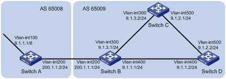
Configuration procedure
1) Configure IP addresses for interfaces (omitted)
2) Configure iBGP connections
# Configure Switch B.
<SwitchB> system-view
[SwitchB] bgp 65009
[SwitchB-bgp] router-id 2.2.2.2
[SwitchB-bgp] peer 9.1.1.2 as-number 65009
[SwitchB-bgp] peer 9.1.3.2 as-number 65009
[SwitchB-bgp] quit
# Configure Switch C.
<SwitchC> system-view
[SwitchC] bgp 65009
[SwitchC-bgp] router-id 3.3.3.3
[SwitchC-bgp] peer 9.1.3.1 as-number 65009
[SwitchC-bgp] peer 9.1.2.2 as-number 65009
[SwitchC-bgp] quit
# Configure Switch D.
<SwitchD> system-view
[SwitchD] bgp 65009
[SwitchD-bgp] router-id 4.4.4.4
[SwitchD-bgp] peer 9.1.1.1 as-number 65009
[SwitchD-bgp] peer 9.1.2.1 as-number 65009
[SwitchD-bgp] quit
3) Configure the eBGP connection
# Configure Switch A.
<SwitchA> system-view
[SwitchA] bgp 65008
[SwitchA-bgp] router-id 1.1.1.1
[SwitchA-bgp] peer 200.1.1.1 as-number 65009
# Inject network 8.0.0.0/8 to the BGP routing table.
[SwitchA-bgp] network 8.0.0.0
[SwitchA-bgp] quit
# Configure Switch B.
[SwitchB] bgp 65009
[SwitchB-bgp] peer 200.1.1.2 as-number 65008
[SwitchB-bgp] quit
# Display BGP peer information on Switch B.
[SwitchB] display bgp peer
BGP local router ID : 2.2.2.2
Local AS number : 65009
Total number of peers : 3 Peers in established state : 3
Peer V AS MsgRcvd MsgSent OutQ PrefRcv Up/Down State
9.1.1.2 4 65009 56 56 0 0 00:40:54 Established
9.1.3.2 4 65009 49 62 0 0 00:44:58 Established
200.1.1.2 4 65008 49 65 0 1 00:44:03 Established
You can find Switch B has established BGP connections to other switches.
# Display BGP routing table information on Switch A.
[SwitchA] display bgp routing-table
Total Number of Routes: 1
BGP Local router ID is 1.1.1.1
Status codes: * - valid, > - best, d - damped,
h - history, i - internal, s - suppressed, S - Stale
Origin : i - IGP, e - EGP, ? - incomplete
Network NextHop MED LocPrf PrefVal Path/Ogn
*> 8.0.0.0 0.0.0.0 0 0 i
# Display BGP routing table information on Switch B.
[SwitchB] display bgp routing-table
Total Number of Routes: 1
BGP Local router ID is 2.2.2.2
Status codes: * - valid, > - best, d - damped,
h - history, i - internal, s - suppressed, S - Stale
Origin : i - IGP, e - EGP, ? - incomplete
Network NextHop MED LocPrf PrefVal Path/Ogn
*> 8.0.0.0 200.1.1.2 0 0 65008i
# Display the BGP routing table on Switch C.
[SwitchC] display bgp routing-table
Total Number of Routes: 1
BGP Local router ID is 3.3.3.3
Status codes: * - valid, > - best, d - damped,
h - history, i - internal, s - suppressed, S - Stale
Origin : i - IGP, e - EGP, ? - incomplete
Network NextHop MED LocPrf PrefVal Path/Ogn
i 8.0.0.0 200.1.1.2 0 100 0 65008i
![]()
From the above outputs, you can find Switch A has learned no route to AS65009, and Switch C has learned network 8.0.0.0 but the next hop 200.1.1.2 is unreachable, so the route is invalid.
4) Redistribute direct routes
# Configure Switch B.
[SwitchB] bgp 65009
[SwitchB-bgp] import-route direct
# Display BGP routing table information on Switch A.
[SwitchA] display bgp routing-table
Total Number of Routes: 7
BGP Local router ID is 1.1.1.1
Status codes: * - valid, > - best, d - damped,
h - history, i - internal, s - suppressed, S - Stale
Origin : i - IGP, e - EGP, ? - incomplete
Network NextHop MED LocPrf PrefVal Path/Ogn
*> 8.0.0.0 0.0.0.0 0 0 i
*> 9.1.1.0/24 200.1.1.1 0 0 65009?
*> 9.1.1.2/32 200.1.1.1 0 0 65009?
*> 9.1.3.0/24 200.1.1.1 0 0 65009?
*> 9.1.3.2/32 200.1.1.1 0 0 65009?
* 200.1.1.0 200.1.1.1 0 0 65009?
* 200.1.1.2/32 200.1.1.1 0 0 65009?
# Display BGP routing table information on Switch C.
[SwitchC] display bgp routing-table
Total Number of Routes: 7
BGP Local router ID is 3.3.3.3
Status codes: * - valid, > - best, d - damped,
h - history, i - internal, s - suppressed, S - Stale
Origin : i - IGP, e - EGP, ? - incomplete
Network NextHop MED LocPrf PrefVal Path/Ogn
*>i 8.0.0.0 200.1.1.2 0 100 0 65008i
*>i 9.1.1.0/24 9.1.3.1 0 100 0 ?
*>i 9.1.1.2/32 9.1.3.1 0 100 0 ?
* i 9.1.3.0/24 9.1.3.1 0 100 0 ?
* i 9.1.3.2/32 9.1.3.1 0 100 0 ?
*>i 200.1.1.0 9.1.3.1 0 100 0 ?
*>i 200.1.1.2/32 9.1.3.1 0 100 0 ?
You can find the route 8.0.0.0 becomes valid with the next hop being Switch A.
# Ping 8.1.1.1 on Switch C.
[SwitchC] ping 8.1.1.1
PING 8.1.1.1: 56 data bytes, press CTRL_C to break
Reply from 8.1.1.1: bytes=56 Sequence=1 ttl=254 time=31 ms
Reply from 8.1.1.1: bytes=56 Sequence=2 ttl=254 time=47 ms
Reply from 8.1.1.1: bytes=56 Sequence=3 ttl=254 time=31 ms
Reply from 8.1.1.1: bytes=56 Sequence=4 ttl=254 time=16 ms
Reply from 8.1.1.1: bytes=56 Sequence=5 ttl=254 time=31 ms
--- 8.1.1.1 ping statistics ---
5 packet(s) transmitted
5 packet(s) received
0.00% packet loss
round-trip min/avg/max = 16/31/47 ms
BGP and IGP Synchronization Configuration
Network requirements
As shown below, OSPF is used as the IGP protocol in AS65009, where Switch C is a non-BGP switch. Between Switch A and Switch B is an eBGP connection.
Network diagram
Figure 1-21 Network diagram for BGP and IGP synchronization
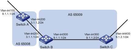
Configuration procedure
1) Configure IP addresses for interfaces (omitted)
2) Configure OSPF (omitted)
3) Configure the eBGP connection
# Configure Switch A.
<SwitchA> system-view
[SwitchA] bgp 65008
[SwitchA-bgp] router-id 1.1.1.1
[SwitchA-bgp] peer 3.1.1.1 as-number 65009
# Inject network 8.1.1.0/24 to the BGP routing table.
[SwitchA-bgp] network 8.1.1.0 24
[SwitchA-bgp] quit
# Configure Switch B.
<SwitchB> system-view
[SwitchB] bgp 65009
[SwitchB-bgp] peer 3.1.1.2 as-number 65008
[SwitchB-bgp] quit
4) Configure BGP and IGP synchronization
# Configure BGP to redistribute routes from OSPF on Switch B.
[SwitchB] bgp 65009
[SwitchB-bgp] import-route ospf 1
[SwitchB-bgp] quit
# Display routing table information on Switch A.
[SwitchA] display bgp routing-table
Total Number of Routes: 3
BGP Local router ID is 1.1.1.1
Status codes: * - valid, > - best, d - damped,
h - history, i - internal, s - suppressed, S - Stale
Origin : i - IGP, e - EGP, ? - incomplete
Network NextHop MED LocPrf PrefVal Path/Ogn
*> 8.1.1.0/24 0.0.0.0 0 0 i
*> 9.1.1.0/24 3.1.1.1 0 0 65009?
# Configure OSPF to redistribute routes from BGP on Switch B.
[SwitchB] ospf
[SwitchB-ospf-1] import-route bgp
[SwitchB-ospf-1] quit
# Display routing table information on Switch C.
<SwitchC> display ip routing-table
Routing Tables: Public
Destinations : 7 Routes : 7
Destination/Mask Proto Pre Cost NextHop Interface
8.1.1.0/24 O_ASE 150 1 9.1.1.1 Vlan300
9.1.1.0/24 Direct 0 0 9.1.1.2 Vlan300
9.1.1.2/32 Direct 0 0 127.0.0.1 InLoop0
9.1.2.0/24 Direct 0 0 9.1.2.1 Vlan400
9.1.2.1/32 Direct 0 0 127.0.0.1 InLoop0
127.0.0.0/8 Direct 0 0 127.0.0.1 InLoop0
127.0.0.1/32 Direct 0 0 127.0.0.1 InLoop0
5) Configure route automatic summarization
# Configure route automatic summarization on Switch B.
[SwitchB] bgp 65009
[SwitchB-bgp] summary automatic
# Display BGP routing table information on Switch A.
[SwitchA] display bgp routing-table
Total Number of Routes: 2
BGP Local router ID is 1.1.1.1
Status codes: * - valid, > - best, d - damped,
h - history, i - internal, s - suppressed, S - Stale
Origin : i - IGP, e - EGP, ? - incomplete
Network NextHop MED LocPrf PrefVal Path/Ogn
*> 8.1.1.0/24 0.0.0.0 0 0 i
*> 9.0.0.0 3.1.1.1 0 0 65009?
# Use ping for verification.
[SwitchA] ping -a 8.1.1.1 9.1.2.1
PING 9.1.2.1: 56 data bytes, press CTRL_C to break
Reply from 9.1.2.1: bytes=56 Sequence=1 ttl=254 time=15 ms
Reply from 9.1.2.1: bytes=56 Sequence=2 ttl=254 time=31 ms
Reply from 9.1.2.1: bytes=56 Sequence=3 ttl=254 time=47 ms
Reply from 9.1.2.1: bytes=56 Sequence=4 ttl=254 time=46 ms
Reply from 9.1.2.1: bytes=56 Sequence=5 ttl=254 time=47 ms
--- 9.1.2.1 ping statistics ---
5 packet(s) transmitted
5 packet(s) received
0.00% packet loss
round-trip min/avg/max = 15/37/47 ms
BGP Load Balancing Configuration
Network requirements
All the switches run BGP. Switch A resides in AS 65008, Switch B and Switch C in AS 65009. Between Switch A and Switch B, Switch A and Switch C are eBGP connections, and between Switch B and Switch C is an iBGP connection. Two routes are configured on Switch A for load balancing.
Network diagram
Figure 1-22 Network diagram for BGP load balancing configuration
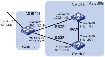
Configuration procedure
1) Configure IP addresses for interfaces (omitted)
2) Configure BGP connections
# Configure Switch A.
<SwitchA> system-view
[SwitchA] bgp 65008
[SwitchA-bgp] router-id 1.1.1.1
[SwitchA-bgp] peer 200.1.1.1 as-number 65009
[SwitchA-bgp] peer 200.1.2.1 as-number 65009
# Inject route 8.0.0.0/8 to BGP routing table.
[SwitchA-bgp] network 8.0.0.0 255.0.0.0
[SwitchA-bgp] quit
# Configure Switch B.
<SwitchB> system-view
[SwitchB] bgp 65009
[SwitchB-bgp] router-id 2.2.2.2
[SwitchB-bgp] peer 200.1.1.2 as-number 65008
[SwitchB-bgp] peer 9.1.1.2 as-number 65009
[SwitchB-bgp] network 9.1.1.0 255.255.255.0
[SwitchB-bgp] quit
# Configure Switch C.
<SwitchC> system-view
[SwitchC] bgp 65009
[SwitchC-bgp] router-id 3.3.3.3
[SwitchC-bgp] peer 200.1.2.2 as-number 65008
[SwitchC-bgp] peer 9.1.1.1 as-number 65009
[SwitchC-bgp] network 9.1.1.0 255.255.255.0
[SwitchC-bgp] quit
# Display the routing table on Switch A.
[SwitchA] display bgp routing-table
Total Number of Routes: 3
BGP Local router ID is 1.1.1.1
Status codes: * - valid, > - best, d - damped,
h - history, i - internal, s - suppressed, S - Stale
Origin : i - IGP, e - EGP, ? - incomplete
Network NextHop MED LocPrf PrefVal Path/Ogn
*> 8.0.0.0 0.0.0.0 0 0 i
*> 9.1.1.0/24 200.1.1.1 0 0 65009i
* 200.1.2.1 0 0 65009i
From the above output information, you can find two valid routes to destination 9.1.1.0/24 are available: the route with next hop 200.1.1.1 is marked with a greater-than sign (>), indicating it is the best route (because the ID of Switch B is smaller); the route with next hop 200.1.2.1 is marked with only an asterisk (*), indicating it is a valid route, but not the best.
3) Configure loading balancing
# Configure Switch A.
[SwitchA] bgp 65008
[SwitchA-bgp] balance 2
[SwitchA-bgp] quit
# Display the routing table on Switch A.
[SwitchA] display bgp routing-table
Total Number of Routes: 3
BGP Local router ID is 1.1.1.1
Status codes: * - valid, > - best, d - damped,
h - history, i - internal, s - suppressed, S - Stale
Origin : i - IGP, e - EGP, ? - incomplete
Network NextHop MED LocPrf PrefVal Path/Ogn
*> 8.0.0.0 0.0.0.0 0 0 i
*> 9.1.1.0/24 200.1.1.1 0 0 65009i
*> 200.1.2.1 0 0 65009i
The route 9.1.1.0/24 has two next hops 200.1.1.1 and 200.1.2.1, both of which are marked with a greater-than sign (>), indicating they are the best routes..
BGP Community Configuration
Network requirements
Switch B establishes eBGP connections with Switch A and C. Configure No_Export community attribute on Switch A to make routes from AS 10 not advertised by AS 20 to any other AS.
Network diagram
Figure 1-23 Network diagram for BGP community configuration
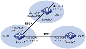
Configuration procedure
1) Configure IP addresses for interfaces (omitted)
2) Configure eBGP
# Configure Switch A.
<SwitchA> system-view
[SwitchA] bgp 10
[SwitchA-bgp] router-id 1.1.1.1
[SwitchA-bgp] peer 200.1.2.2 as-number 20
[SwitchA-bgp] network 9.1.1.0 255.255.255.0
[SwitchA-bgp] quit
# Configure Switch B.
<SwitchB> system-view
[SwitchB] bgp 20
[SwitchB-bgp] router-id 2.2.2.2
[SwitchB-bgp] peer 200.1.2.1 as-number 10
[SwitchB-bgp] peer 200.1.3.2 as-number 30
[SwitchB-bgp] quit
# Configure Switch C.
<SwitchC> system-view
[SwitchC] bgp 30
[SwitchC-bgp] router-id 3.3.3.3
[SwitchC-bgp] peer 200.1.3.1 as-number 20
[SwitchC-bgp] quit
# Display the BGP routing table on Switch B.
[SwitchB] display bgp routing-table 9.1.1.0
BGP local router ID : 2.2.2.2
Local AS number : 20
Paths: 1 available, 1 best
BGP routing table entry information of 9.1.1.0/24:
From : 200.1.2.1 (1.1.1.1)
Original nexthop: 200.1.2.1
AS-path : 10
Origin : igp
Attribute value : MED 0, pref-val 0, pre 255
State : valid, external, best,
Advertised to such 1 peers:
200.1.3.2
Switch B advertised routes to Switch C in AS 30.
# Display the routing table on Switch C.
[SwitchC] display bgp routing-table
Total Number of Routes: 1
BGP Local router ID is 3.3.3.3
Status codes: * - valid, > - best, d - damped,
h - history, i - internal, s - suppressed, S - Stale
Origin : i - IGP, e - EGP, ? - incomplete
Network NextHop MED LocPrf PrefVal Path/Ogn
*> 9.1.1.0/24 200.1.3.1 0 0 20 10i
Switch C learned route 9.1.1.0/24 from Switch B.
3) Configure BGP community
# Configure a routing policy.
[SwitchA] route-policy comm_policy permit node 0
[SwitchA-route-policy] apply community no-export
[SwitchA-route-policy] quit
# Apply the routing policy.
[SwitchA] bgp 10
[SwitchA-bgp] peer 200.1.2.2 route-policy comm_policy export
[SwitchA-bgp] peer 200.1.2.2 advertise-community
# Display the routing table on Switch B.
[SwitchB] display bgp routing-table 9.1.1.0
BGP local router ID : 2.2.2.2
Local AS number : 20
Paths: 1 available, 1 best
BGP routing table entry information of 9.1.1.0/24:
From : 200.1.2.1 (1.1.1.1)
Original nexthop: 200.1.2.1
Community : No-Export
AS-path : 10
Origin : igp
Attribute value : MED 0, pref-val 0, pre 255
State : valid, external, best,
Not advertised to any peers yet
The output information shows that:
l Switch F can send route information to Switch B and Switch C through the confederation by establishing only an eBGP connection with Switch A.
l Switch B and Switch D are in the same confederation, but belong to different sub ASs. They obtain external route information from Switch A and generate the same BGP route entries; it seems like that they reside in the same AS although they have no direct connection in between.
BGP Route Reflector Configuration
Network requirements
In the following figure, all switches run BGP.
l Between Switch A and Switch B is an eBGP connection, between Switch C and Switch B, and between Switch C and Switch D are iBGP connections.
l Switch C is a route reflector with clients Switch B and D.
l Switch D can learn route 1.0.0.0/8 from Switch C.
Network diagram
Figure 1-24 Network diagram for BGP route reflector configuration
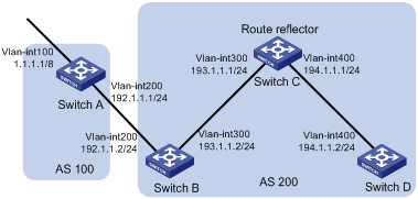
Configuration procedure
1) Configure IP addresses for interfaces (omitted)
2) Configure BGP connections
# Configure Switch A.
<SwitchA> system-view
[SwitchA] bgp 100
[SwitchA-bgp] router-id 1.1.1.1
[SwitchA-bgp] peer 192.1.1.2 as-number 200
# Inject network 1.0.0.0/8 to the BGP routing table.
[SwitchA-bgp] network 1.0.0.0
[SwitchA-bgp] quit
# Configure Switch B.
<SwitchB> system-view
[SwitchB] bgp 200
[SwitchB-bgp] router-id 2.2.2.2
[SwitchB-bgp] peer 192.1.1.1 as-number 100
[SwitchB-bgp] peer 193.1.1.1 as-number 200
[SwitchB-bgp] peer 193.1.1.1 next-hop-local
[SwitchB-bgp] quit
# Configure Switch C.
<SwitchC> system-view
[SwitchC] bgp 200
[SwitchC-bgp] router-id 3.3.3.3
[SwitchC-bgp] peer 193.1.1.2 as-number 200
[SwitchC-bgp] peer 194.1.1.2 as-number 200
[SwitchC-bgp] quit
# Configure Switch D.
<SwitchD> system-view
[SwitchD] bgp 200
[SwitchD-bgp] router-id 4.4.4.4
[SwitchD-bgp] peer 194.1.1.1 as-number 200
[SwitchD-bgp] quit
3) Configure the route reflector
# Configure Switch C.
[SwitchC] bgp 200
[SwitchC-bgp] peer 193.1.1.2 reflect-client
[SwitchC-bgp] peer 194.1.1.2 reflect-client
[SwitchC-bgp] quit
4) Verify the above configuration
# Display the BGP routing table on Switch B.
[SwitchB] display bgp routing-table
Total Number of Routes: 1
BGP Local router ID is 200.1.2.2
Status codes: * - valid, > - best, d - damped,
h - history, i - internal, s - suppressed, S - Stale
Origin : i - IGP, e - EGP, ? - incomplete
Network NextHop MED LocPrf PrefVal Path/Ogn
*> 1.0.0.0 192.1.1.1 0 0 100i
# Display the BGP routing table on Switch D.
[SwitchD] display bgp routing-table
Total Number of Routes: 1
BGP Local router ID is 200.1.2.1
Status codes: * - valid, > - best, d - damped,
h - history, i - internal, s - suppressed, S - Stale
Origin : i - IGP, e - EGP, ? - incomplete
Network NextHop MED LocPrf PrefVal Path/Ogn
i 1.0.0.0 193.1.1.2 0 100 0 100i
Switch D learned route 1.0.0.0/8 from Switch C.
BGP Confederation Configuration
Network requirements
To reduce iBGP connections in AS 200, split it into three sub-ASs, AS65001, AS65002 and AS65003. Switches in AS65001 are fully meshed.
Network diagram
Figure 1-25 Network diagram for BGP confederation configuration
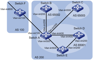
|
Device |
Interface |
IP address |
Device |
Interface |
IP address |
|
Switch A |
Vlan-int100 |
200.1.1.1/24 |
Switch D |
Vlan-int200 |
10.1.5.1/24 |
|
|
Vlan-int200 |
10.1.1.1/24 |
|
Vlan-int400 |
10.1.3.2/24 |
|
|
Vlan-int300 |
10.1.2.1/24 |
Switch E |
Vlan-int200 |
10.1.5.2/24 |
|
|
Vlan-int400 |
10.1.3.1/24 |
|
Vlan-int500 |
10.1.4.2/24 |
|
|
Vlan-int500 |
10.1.4.1/24 |
Switch F |
Vlan-int100 |
200.1.1.2/24 |
|
Switch B |
Vlan-int200 |
10.1.1.2/24 |
|
Vlan-int600 |
9.1.1.1/24 |
|
Switch C |
Vlan-int300 |
10.1.2.2/24 |
|
|
|
Configuration procedure
1) Configure IP addresses for interfaces (omitted)
2) Configure BGP confederation
# Configure Switch A.
<SwitchA> system-view
[SwitchA] bgp 65001
[SwitchA-bgp] router-id 1.1.1.1
[SwitchA-bgp] confederation id 200
[SwitchA-bgp] confederation peer-as 65002 65003
[SwitchA-bgp] peer 10.1.1.2 as-number 65002
[SwitchA-bgp] peer 10.1.1.2 next-hop-local
[SwitchA-bgp] peer 10.1.2.2 as-number 65003
[SwitchA-bgp] peer 10.1.2.2 next-hop-local
[SwitchA-bgp] quit
# Configure Switch B.
<SwitchB> system-view
[SwitchB] bgp 65002
[SwitchB-bgp] router-id 2.2.2.2
[SwitchB-bgp] confederation id 200
[SwitchB-bgp] confederation peer-as 65001 65003
[SwitchB-bgp] peer 10.1.1.1 as-number 65001
[SwitchB-bgp] quit
# Configure Switch C.
<SwitchC> system-view
[SwitchC] bgp 65003
[SwitchC-bgp] router-id 3.3.3.3
[SwitchC-bgp] confederation id 200
[SwitchC-bgp] confederation peer-as 65001 65002
[SwitchC-bgp] peer 10.1.2.1 as-number 65001
[SwitchC-bgp] quit
3) Configure iBGP connections in AS65001.
# Configure Switch A.
[SwitchA] bgp 65001
[SwitchA-bgp] peer 10.1.3.2 as-number 65001
[SwitchA-bgp] peer 10.1.3.2 next-hop-local
[SwitchA-bgp] peer 10.1.4.2 as-number 65001
[SwitchA-bgp] peer 10.1.4.2 next-hop-local
[SwitchA-bgp] quit
# Configure Switch D.
<SwitchD> system-view
[SwitchD] bgp 65001
[SwitchD-bgp] router-id 4.4.4.4
[SwitchD-bgp] confederation id 200
[SwitchD-bgp] peer 10.1.3.1 as-number 65001
[SwitchD-bgp] peer 10.1.5.2 as-number 65001
[SwitchD-bgp] quit
# Configure Switch E.
<SwitchE> system-view
[SwitchE] bgp 65001
[SwitchE-bgp] router-id 5.5.5.5
[SwitchE-bgp] confederation id 200
[SwitchE-bgp] peer 10.1.4.1 as-number 65001
[SwitchE-bgp] peer 10.1.5.1 as-number 65001
[SwitchE-bgp] quit
4) Configure the eBGP connection between AS100 and AS200.
# Configure Switch A.
[SwitchA] bgp 65001
[SwitchA-bgp] peer 200.1.1.2 as-number 100
[SwitchA-bgp] quit
# Configure Switch F.
<SwitchF> system-view
[SwitchF] bgp 100
[SwitchF-bgp] router-id 6.6.6.6
[SwitchF-bgp] peer 200.1.1.1 as-number 200
[SwitchF-bgp] network 9.1.1.0 255.255.255.0
[SwitchF-bgp] quit
5) Verify above configuration
# Display the routing table on Switch B.
[SwitchB] display bgp routing-table
Total Number of Routes: 1
BGP Local router ID is 2.2.2.2
Status codes: * - valid, > - best, d - damped,
h - history, i - internal, s - suppressed, S - Stale
Origin : i - IGP, e - EGP, ? - incomplete
Network NextHop MED LocPrf PrefVal Path/Ogn
*>i 9.1.1.0/24 10.1.1.1 0 100 0 (65001) 100i
[SwitchB] display bgp routing-table 9.1.1.0
BGP local router ID : 2.2.2.2
Local AS number : 65002
Paths: 1 available, 1 best
BGP routing table entry information of 9.1.1.0/24:
From : 10.1.1.1 (1.1.1.1)
Relay Nexthop : 0.0.0.0
Original nexthop: 10.1.1.1
AS-path : (65001) 100
Origin : igp
Attribute value : MED 0, localpref 100, pref-val 0, pre 255
State : valid, external-confed, best,
Not advertised to any peers yet
# Display the BGP routing table on Switch D.
[SwitchD] display bgp routing-table
Total Number of Routes: 1
BGP Local router ID is 4.4.4.4
Status codes: * - valid, > - best, d - damped,
h - history, i - internal, s - suppressed, S - Stale
Origin : i - IGP, e - EGP, ? - incomplete
Network NextHop MED LocPrf PrefVal Path/Ogn
*>i 9.1.1.0/24 10.1.3.1 0 100 0 100i
[SwitchD] display bgp routing-table 9.1.1.0
BGP local router ID : 4.4.4.4
Local AS number : 65001
Paths: 1 available, 1 best
BGP routing table entry information of 9.1.1.0/24:
From : 10.1.3.1 (1.1.1.1)
Relay Nexthop : 0.0.0.0
Original nexthop: 10.1.3.1
AS-path : 100
Origin : igp
Attribute value : MED 0, localpref 100, pref-val 0, pre 255
State : valid, internal, best,
Not advertised to any peers yet
BGP Path Selection Configuration
Network requirements
l In the figure below, all switches run BGP. Between Switch A and Switch B, and between Switch A and Switch C are eBGP connections. Between Switch B and Switch D, and between Switch D and Switch C are iBGP connections.
l OSPF is the IGP protocol in AS 200.
l Configure routing policies, making Switch D use the route 1.0.0.0/8 from Switch C as the optimal.
Network diagram
Figure 1-26 Network diagram for BGP path selection configuration
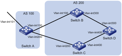
|
Device |
Interface |
IP address |
Device |
Interface |
IP address |
|
Switch A |
Vlan-int101 |
1.0.0.0/8 |
Switch D |
Vlan-int400 |
195.1.1.1/24 |
|
|
Vlan-int100 |
192.1.1.1/24 |
|
Vlan-int300 |
194.1.1.1/24 |
|
|
Vlan-int200 |
193.1.1.1/24 |
Switch C |
Vlan-int400 |
195.1.1.2/24 |
|
Switch B |
Vlan-int100 |
192.1.1.2/24 |
|
Vlan-int200 |
193.1.1.2/24 |
|
|
Vlan-int300 |
194.1.1.2/24 |
|
|
|
Configuration procedure
1) Configure IP addresses for interfaces (omitted).
2) Configure OSPF on Switch B, C, and D.
# Configure Switch B.
<SwitchB> system-view
[SwitchB] ospf
[SwitchB-ospf] area 0
[SwitchB-ospf-1-area-0.0.0.0] network 192.1.1.0 0.0.0.255
[SwitchB-ospf-1-area-0.0.0.0] network 194.1.1.0 0.0.0.255
[SwitchB-ospf-1-area-0.0.0.0] quit
[SwitchB-ospf-1] quit
# Configure Switch C.
<SwitchC> system-view
[SwitchC] ospf
[SwitchC-ospf] area 0
[SwitchC-ospf-1-area-0.0.0.0] network 193.1.1.0 0.0.0.255
[SwitchC-ospf-1-area-0.0.0.0] network 195.1.1.0 0.0.0.255
[SwitchC-ospf-1-area-0.0.0.0] quit
[SwitchC-ospf-1] quit
# Configure Switch D.
<SwitchD> system-view
[SwitchD] ospf
[SwitchD-ospf] area 0
[SwitchD-ospf-1-area-0.0.0.0] network 194.1.1.0 0.0.0.255
[SwitchD-ospf-1-area-0.0.0.0] network 195.1.1.0 0.0.0.255
[SwitchD-ospf-1-area-0.0.0.0] quit
[SwitchD-ospf-1] quit
3) Configure BGP connections
# Configure Switch A.
<SwitchA> system-view
[SwitchA] bgp 100
[SwitchA-bgp] peer 192.1.1.2 as-number 200
[SwitchA-bgp] peer 193.1.1.2 as-number 200
# Inject network 1.0.0.0/8 to the BGP routing table on Switch A.
[SwitchA-bgp] network 1.0.0.0 8
[SwitchA-bgp] quit
# Configure Switch B.
[SwitchB] bgp 200
[SwitchB-bgp] peer 192.1.1.1 as-number 100
[SwitchB-bgp] peer 194.1.1.1 as-number 200
[SwitchB-bgp] quit
# Configure Switch C.
[SwitchC] bgp 200
[SwitchC-bgp] peer 193.1.1.1 as-number 100
[SwitchC-bgp] peer 195.1.1.1 as-number 200
[SwitchC-bgp] quit
# Configure Switch D.
[SwitchD] bgp 200
[SwitchD-bgp] peer 194.1.1.2 as-number 200
[SwitchD-bgp] peer 195.1.1.2 as-number 200
[SwitchD-bgp] quit
4) Configure attributes for route 1.0.0.0/8, making Switch D give priority to the route learned from Switch C.
l Configure a higher MED value for the route 1.0.0.0/8 advertised from Switch A to peer 192.1.1.2.
# Define an ACL numbered 2000 to permit route 1.0.0.0/8.
[SwitchA] acl number 2000
[SwitchA-acl-basic-2000] rule permit source 1.0.0.0 0.255.255.255
[SwitchA-acl-basic-2000] quit
# Define two routing policies, apply_med_50, which sets the MED for route 1.0.0.0/8 to 50, and apply_med_100, which sets the MED for route 1.0.0.0/8 to 100.
[SwitchA] route-policy apply_med_50 permit node 10
[SwitchA-route-policy] if-match acl 2000
[SwitchA-route-policy] apply cost 50
[SwitchA-route-policy] quit
[SwitchA] route-policy apply_med_100 permit node 10
[SwitchA-route-policy] if-match acl 2000
[SwitchA-route-policy] apply cost 100
[SwitchA-route-policy] quit
# Apply routing policy apply_med_50 to the route advertised to peer 193.1.1.2 (Switch C), and apply_med_100 to the route advertised to peer 192.1.1.2 (Switch B).
[SwitchA] bgp 100
[SwitchA-bgp] peer 193.1.1.2 route-policy apply_med_50 export
[SwitchA-bgp] peer 192.1.1.2 route-policy apply_med_100 export
[SwitchA-bgp] quit
# Display the BGP routing table on Switch D.
[SwitchD] display bgp routing-table
Total Number of Routes: 2
BGP Local router ID is 194.1.1.1
Status codes: * - valid, > - best, d - damped,
h - history, i - internal, s - suppressed, S - Stale
Origin : i - IGP, e - EGP, ? - incomplete
Network NextHop MED LocPrf PrefVal Path/Ogn
*>i 1.0.0.0 193.1.1.1 50 100 0 100i
* i 192.1.1.1 100 100 0 100i
You can find route 1.0.0.0/8 is the optimal.
l Configure different local preferences on Switch B and C for route 1.0.0.0/8, making Switch D give priority to the route from Switch C.
# Define an ACL numbered 2000 on Router C, permitting route 1.0.0.0/8.
[SwitchC] acl number 2000
[SwitchC-acl-basic-2000] rule permit source 1.0.0.0 0.255.255.255
[SwitchC-acl-basic-2000] quit
# Configure a routing policy named localpref on Switch C, setting the local preference of route 1.0.0.0/8 to 200 (the default is 100).
[SwitchC] route-policy localpref permit node 10
[SwitchC-route-policy] if-match acl 2000
[SwitchC-route-policy] apply local-preference 200
[SwitchC-route-policy] quit
# Apply routing policy localpref to routes from peer 193.1.1.1.
[SwitchC] bgp 200
[SwitchC-bgp] peer 193.1.1.1 route-policy localpref import
[SwitchC-bgp] quit
# Display the routing table on Switch D.
[SwitchD] display bgp routing-table
Total Number of Routes: 2
BGP Local router ID is 194.1.1.1
Status codes: * - valid, > - best, d - damped,
h - history, i - internal, s - suppressed, S - Stale
Origin : i - IGP, e - EGP, ? - incomplete
Network NextHop MED LocPrf PrefVal Path/Ogn
*>i 1.0.0.0 193.1.1.1 0 200 0 100i
* i 192.1.1.1 0 100 0 100i
You can find route 1.0.0.0/8 from Switch D to Switch C is the optimal.
Troubleshooting BGP
No BGP Peer Relationship Established
Symptom
Display BGP peer information using the display bgp peer command. The state of the connection to a peer cannot become established.
Analysis
To become BGP peers, any two routers need to establish a TCP session using port 179 and exchange open messages successfully.
Solution
1) Use the display current-configuration command to verify the peer’s AS number.
2) Use the display bgp peer command to verify the peer’s IP address.
3) If the loopback interface is used, check whether the peer connect-interface command is configured.
4) If the peer is a non-direct eBGP peer, check whether the peer ebgp-max-hop command is configured.
5) Check whether a route to the peer is available in the routing table.
6) Use the ping command to check connectivity.
7) Use the display tcp status command to check the TCP connection.
8) Check whether an ACL disabling TCP port 179 is configured.
